EP2002104B1 - Pièce supérieure d'un piston assemblé - Google Patents
Pièce supérieure d'un piston assemblé Download PDFInfo
- Publication number
- EP2002104B1 EP2002104B1 EP07722095.2A EP07722095A EP2002104B1 EP 2002104 B1 EP2002104 B1 EP 2002104B1 EP 07722095 A EP07722095 A EP 07722095A EP 2002104 B1 EP2002104 B1 EP 2002104B1
- Authority
- EP
- European Patent Office
- Prior art keywords
- piston
- contact surface
- ring
- radially
- profile
- Prior art date
- Legal status (The legal status is an assumption and is not a legal conclusion. Google has not performed a legal analysis and makes no representation as to the accuracy of the status listed.)
- Active
Links
Images
Classifications
-
- F—MECHANICAL ENGINEERING; LIGHTING; HEATING; WEAPONS; BLASTING
- F16—ENGINEERING ELEMENTS AND UNITS; GENERAL MEASURES FOR PRODUCING AND MAINTAINING EFFECTIVE FUNCTIONING OF MACHINES OR INSTALLATIONS; THERMAL INSULATION IN GENERAL
- F16J—PISTONS; CYLINDERS; SEALINGS
- F16J1/00—Pistons; Trunk pistons; Plungers
- F16J1/09—Pistons; Trunk pistons; Plungers with means for guiding fluids
-
- F—MECHANICAL ENGINEERING; LIGHTING; HEATING; WEAPONS; BLASTING
- F02—COMBUSTION ENGINES; HOT-GAS OR COMBUSTION-PRODUCT ENGINE PLANTS
- F02F—CYLINDERS, PISTONS OR CASINGS, FOR COMBUSTION ENGINES; ARRANGEMENTS OF SEALINGS IN COMBUSTION ENGINES
- F02F3/00—Pistons
- F02F3/0015—Multi-part pistons
- F02F3/0023—Multi-part pistons the parts being bolted or screwed together
-
- F—MECHANICAL ENGINEERING; LIGHTING; HEATING; WEAPONS; BLASTING
- F02—COMBUSTION ENGINES; HOT-GAS OR COMBUSTION-PRODUCT ENGINE PLANTS
- F02F—CYLINDERS, PISTONS OR CASINGS, FOR COMBUSTION ENGINES; ARRANGEMENTS OF SEALINGS IN COMBUSTION ENGINES
- F02F3/00—Pistons
Definitions
- the invention relates to an upper part of a built-up piston according to the preamble of claim 1.
- a built piston consisting of a top and a bottom in which a highly wear-resistant layer is disposed between these surfaces to reduce frictional wear of the contacting surfaces of the top and bottom.
- the layer is applied by the detonation spray method on one of the two contact surfaces in order to ensure good adhesion of the layer to the contact surface.
- the layer may consist of a tungsten carbide-cobalt lamination or of a copper-nickel-indium alloy. This has the disadvantage that both the materials that make up the layer and the detonation spray process are very costly.
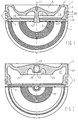
- Fig. 1 shows an upper part 1 of a piston whose lower part is not shown in the figure. Is marked in Fig. 1 half the bottom view of the upper part 1, which shows an inner, radially aligned contact surfaces 2 and an outer, radially aligned contact surface 3, wherein the upper part 1 rests on the contact surfaces 2 and 3 on the lower part of the piston 1.
- the upper part 1 is made of steel.
- the lower part can be made of steel, aluminum or cast iron with nodular graphite.
- the upper part 1 has a combustion bowl 5 molded into its piston head 4.
- the piston-bottom-side region of the radial outer side of the upper part 1 is designed as a land land 6, which is followed in a direction away from the piston crown by a ring part 7 with three annular grooves 8, 9 and 10.
- the piston bottom facing away from the underside of the upper part 1 has coaxial with the piston axis 11, a threaded bolt 12 through which the upper part 1 is bolted to the lower part of the piston.
- a radially inner, annular recesses 13 and a radially outer, annular recess 14 are arranged on the underside of the upper part 1, which together with piston bottom side recesses in the lower part form closed ring channels for the passage of cooling oil.
- the inner recess 13 is bounded radially inwardly by the threaded bolt 12 and radially outwardly by an annular rib 15 arranged between the recesses 13 and 14.
- the outer recess 14 is radially inwardly of the annular rib 15 and radially outward from one to the piston crown 4 molded annular wall 25 limited, on the radial outer side of the top land 6 and the ring section 7 are arranged.
- the piston bottom facing away from the bottom of the annular rib 15 carries the inner contact surface 2.
- a circumferential recess 16 is radially inwardly formed, which has the outer bearing surface 3.
- a profile with a groove shape which likewise conforms to the standard DIN EN ISO 1302, and which is described in more detail with the graphic symbols X (crossed grooves) or the graphic symbol R (grooves in the form of radially arranged sheets).
- Fig. 2 shows the upper part 17 of a built piston, which is different from the in Fig. 1 illustrated upper part 1 differs in that it has on the bottom side facing away from the bottom coaxial with the piston axis 24 blind hole 18 having an internal thread 19 into which a screw for assembling the upper part 17 with a in Fig. 2 not shown lower part can be screwed.
- Another difference between the two tops 1 and 17 is that the top 17 only the piston bottom facing away, radially aligned inner contact surface 20 of the annular rib 21 which is disposed between an outer recess 22 and an inner recess 23 on the underside of the upper part 17 , has a profile in the form of concentric grooves, as shown in the lower half view of the upper part 17 shows. In the Fig. 2 shown profiling of only one of the two bearing surfaces is sufficient at lower ignition pressures less highly loaded piston.
Landscapes
- Engineering & Computer Science (AREA)
- General Engineering & Computer Science (AREA)
- Chemical & Material Sciences (AREA)
- Combustion & Propulsion (AREA)
- Mechanical Engineering (AREA)
- Pistons, Piston Rings, And Cylinders (AREA)
Claims (1)
- Pièce supérieure (1, 17) d'un piston assemblé,- avec un fond de piston (4),- avec une paroi annulaire (25) formée au niveau du fond de piston (4) dans la direction opposée au fond de piston, sur la surface extérieure radiale de laquelle est disposée une partie annulaire (7),- avec un évidement (14, 22) extérieur de forme annulaire, formé dans le côté inférieur opposé au fond de piston, lequel évidement est délimité radialement côté extérieur par la paroi annulaire (25) et radialement à l'intérieur par une nervure annulaire (15, 21) formée au niveau du côté inférieur de la partie supérieure (1, 17),- avec une surface de contact intérieure (2, 20) disposée sur le côté inférieur de la nervure annulaire (15, 21), orientée de manière radiale, et- avec une surface de contact extérieure (3) disposée sur le côté inférieur de la paroi annulaire (25), orientée de manière radiale,- dans laquelle la surface de contact intérieure (2, 20) présente un profil en forme de rainure avec une rugosité moyenne comprise entre Rz 10 et Rz 30,caractérisée en ce- que le profil de la surface de contact intérieure (2, 20) a la forme de rainures disposées de manière concentrique avec un espacement entre les rainures compris entre 300 µm et 1 200 µm,- qu'à côté de la surface de contact intérieure (2, 20), la surface de contact extérieure (3) présente également un profil en forme de rainure avec une rugosité moyenne comprise entre Rz 10 et Rz 30, dans laquelle le profil a la forme de rainures disposées de manière concentrique avec un espacement entre les rainures compris entre 300 µm et 1200 µm.
Applications Claiming Priority (2)
| Application Number | Priority Date | Filing Date | Title |
|---|---|---|---|
| DE102006015587A DE102006015587A1 (de) | 2006-04-04 | 2006-04-04 | Oberteil eines gebauten Kolbens |
| PCT/DE2007/000536 WO2007115528A1 (fr) | 2006-04-04 | 2007-03-23 | Pièce supérieure d'un piston assemblé |
Publications (2)
| Publication Number | Publication Date |
|---|---|
| EP2002104A1 EP2002104A1 (fr) | 2008-12-17 |
| EP2002104B1 true EP2002104B1 (fr) | 2017-05-10 |
Family
ID=38326771
Family Applications (1)
| Application Number | Title | Priority Date | Filing Date |
|---|---|---|---|
| EP07722095.2A Active EP2002104B1 (fr) | 2006-04-04 | 2007-03-23 | Pièce supérieure d'un piston assemblé |
Country Status (7)
| Country | Link |
|---|---|
| US (1) | US8079299B2 (fr) |
| EP (1) | EP2002104B1 (fr) |
| JP (1) | JP5091227B2 (fr) |
| KR (1) | KR101443396B1 (fr) |
| CN (1) | CN101415929B (fr) |
| DE (1) | DE102006015587A1 (fr) |
| WO (1) | WO2007115528A1 (fr) |
Families Citing this family (1)
| Publication number | Priority date | Publication date | Assignee | Title |
|---|---|---|---|---|
| DE102006055251A1 (de) | 2006-11-23 | 2008-05-29 | Mahle International Gmbh | Zweiteiliger Kolben für einen Verbrennungsmotor |
Family Cites Families (11)
| Publication number | Priority date | Publication date | Assignee | Title |
|---|---|---|---|---|
| CH406736A (de) * | 1962-09-11 | 1966-01-31 | Mirrlees National Limited | Kolben für Verbrennungskraftmaschine |
| US3465651A (en) * | 1968-02-13 | 1969-09-09 | Alco Products Inc | Composite pistons |
| DE2832970A1 (de) * | 1978-07-27 | 1980-02-07 | Schmidt Gmbh Karl | Gebauter, fluessigkeitsgekuehlter kolben fuer brennkraftmaschinen |
| DE2936630C2 (de) * | 1979-09-11 | 1985-05-09 | Mtu Motoren- Und Turbinen-Union Friedrichshafen Gmbh, 7990 Friedrichshafen | Kolben für eine Brennkraftmaschine |
| DE3633134A1 (de) * | 1986-09-30 | 1988-04-07 | Man B & W Diesel Gmbh | Gebauter kolben fuer brennkraftmaschinen |
| DE3926791A1 (de) * | 1989-08-14 | 1991-02-21 | Kriegler Franz | Brennkraftmaschinenkolben |
| DE4129746C2 (de) * | 1991-09-06 | 1994-04-14 | Man B & W Diesel Ag | Gebauter Kolben für Hubkolbenmaschinen |
| JPH08210180A (ja) * | 1995-02-03 | 1996-08-20 | Mitsubishi Heavy Ind Ltd | ピストン |
| DK176124B1 (da) * | 1999-04-07 | 2006-09-11 | Man B & W Diesel As | Stempel og stempelstang til en forbrændingsmotor |
| FI113683B (fi) * | 2001-06-04 | 2004-05-31 | Waertsilae Finland Oy | Polttomoottorin mäntäyksikkö |
| DE102004027974A1 (de) * | 2004-06-08 | 2005-12-29 | Mahle Gmbh | Gebauter Kolben und Verfahren zur Vermeidung von Beschädigungen in Kontakt zueinander stehender Flächen des Oberteiles und des Unterteiles des Kolbens |
-
2006
- 2006-04-04 DE DE102006015587A patent/DE102006015587A1/de not_active Withdrawn
-
2007
- 2007-03-23 EP EP07722095.2A patent/EP2002104B1/fr active Active
- 2007-03-23 KR KR1020087024114A patent/KR101443396B1/ko active Active
- 2007-03-23 JP JP2009503402A patent/JP5091227B2/ja not_active Expired - Fee Related
- 2007-03-23 CN CN2007800124248A patent/CN101415929B/zh active Active
- 2007-03-23 US US12/225,900 patent/US8079299B2/en active Active
- 2007-03-23 WO PCT/DE2007/000536 patent/WO2007115528A1/fr not_active Ceased
Also Published As
| Publication number | Publication date |
|---|---|
| WO2007115528A1 (fr) | 2007-10-18 |
| JP2009532612A (ja) | 2009-09-10 |
| JP5091227B2 (ja) | 2012-12-05 |
| DE102006015587A1 (de) | 2007-10-11 |
| US20090173224A1 (en) | 2009-07-09 |
| EP2002104A1 (fr) | 2008-12-17 |
| US8079299B2 (en) | 2011-12-20 |
| KR20090004901A (ko) | 2009-01-12 |
| CN101415929B (zh) | 2011-12-28 |
| CN101415929A (zh) | 2009-04-22 |
| KR101443396B1 (ko) | 2014-09-24 |
Similar Documents
| Publication | Publication Date | Title |
|---|---|---|
| DE3604661C2 (fr) | ||
| EP1828587B1 (fr) | Piston refroidi et en plusieurs parties destine a un moteur a combustion interne | |
| EP2129899B1 (fr) | Piston pour un moteur à combustion interne | |
| DE102008056203A1 (de) | Mehrteiliger Kolben für einen Verbrennungsmotor und Verfahren zu seiner Herstellung | |
| EP1546536B1 (fr) | Piston monobloc a conduite de refroidissement pour moteur a combustion interne | |
| DE102006055251A1 (de) | Zweiteiliger Kolben für einen Verbrennungsmotor | |
| EP1583897B1 (fr) | Procede pour creer des alesages "shaker" dans le canal de refroidissement d'un piston monobloc | |
| WO2010051878A1 (fr) | Piston avec canal de refroidissement pour un moteur à combustion interne, avec un élément de fermeture qui ferme le canal de refroidissement | |
| EP3334918A1 (fr) | Piston pour moteur à combustion interne | |
| EP0714485A1 (fr) | Piston en metal leger pour moteurs a combustion interne tres sollicites | |
| DD286026A5 (de) | Zylinderkopf-brennraumabdichtung fuer einen hubkolbenmotor | |
| DE2709359A1 (de) | Kolbenring fuer hubkolben-brennkraftmaschinen | |
| WO2007025622A1 (fr) | Piston pourvu d'un evidement radial peripherique place en dessous d'une rainure annulaire | |
| EP1819922A1 (fr) | Piston en deux parties d'un moteur a combustion interne | |
| DE10340291A1 (de) | Kolben für einen Verbrennungsmotor | |
| DE102015006354A1 (de) | Kolben für einen Verbrennungsmotor | |
| WO2013004218A1 (fr) | Piston pour un moteur à combustion interne | |
| DE10321034B3 (de) | Hubkolbenbrennkraftmaschine | |
| DE102017205152A1 (de) | Kolben mit nutboden variabler tiefe | |
| EP2002104A1 (fr) | Pièce supérieure d'un piston assemblé | |
| DE3538978C1 (en) | Piston-ring arrangement for trunk pistons | |
| EP3850249B1 (fr) | Segment de piston et piston à scellement intérieur de rainure | |
| DE102017215834A1 (de) | Kolben | |
| DE102009018981A1 (de) | Kolben für eine Hubkolbenmaschine | |
| DE102011083134A1 (de) | Pleuel |
Legal Events
| Date | Code | Title | Description |
|---|---|---|---|
| PUAI | Public reference made under article 153(3) epc to a published international application that has entered the european phase |
Free format text: ORIGINAL CODE: 0009012 |
|
| 17P | Request for examination filed |
Effective date: 20080926 |
|
| AK | Designated contracting states |
Kind code of ref document: A1 Designated state(s): DE ES FI FR GB IT |
|
| DAX | Request for extension of the european patent (deleted) | ||
| RBV | Designated contracting states (corrected) |
Designated state(s): DE ES FI FR GB IT |
|
| 17Q | First examination report despatched |
Effective date: 20100614 |
|
| GRAP | Despatch of communication of intention to grant a patent |
Free format text: ORIGINAL CODE: EPIDOSNIGR1 |
|
| INTG | Intention to grant announced |
Effective date: 20161222 |
|
| GRAS | Grant fee paid |
Free format text: ORIGINAL CODE: EPIDOSNIGR3 |
|
| GRAA | (expected) grant |
Free format text: ORIGINAL CODE: 0009210 |
|
| AK | Designated contracting states |
Kind code of ref document: B1 Designated state(s): DE ES FI FR GB IT |
|
| REG | Reference to a national code |
Ref country code: GB Ref legal event code: FG4D Free format text: NOT ENGLISH |
|
| REG | Reference to a national code |
Ref country code: DE Ref legal event code: R096 Ref document number: 502007015631 Country of ref document: DE |
|
| PG25 | Lapsed in a contracting state [announced via postgrant information from national office to epo] |
Ref country code: ES Free format text: LAPSE BECAUSE OF FAILURE TO SUBMIT A TRANSLATION OF THE DESCRIPTION OR TO PAY THE FEE WITHIN THE PRESCRIBED TIME-LIMIT Effective date: 20170510 |
|
| REG | Reference to a national code |
Ref country code: DE Ref legal event code: R097 Ref document number: 502007015631 Country of ref document: DE |
|
| PG25 | Lapsed in a contracting state [announced via postgrant information from national office to epo] |
Ref country code: IT Free format text: LAPSE BECAUSE OF FAILURE TO SUBMIT A TRANSLATION OF THE DESCRIPTION OR TO PAY THE FEE WITHIN THE PRESCRIBED TIME-LIMIT Effective date: 20170510 |
|
| PLBE | No opposition filed within time limit |
Free format text: ORIGINAL CODE: 0009261 |
|
| STAA | Information on the status of an ep patent application or granted ep patent |
Free format text: STATUS: NO OPPOSITION FILED WITHIN TIME LIMIT |
|
| 26N | No opposition filed |
Effective date: 20180213 |
|
| GBPC | Gb: european patent ceased through non-payment of renewal fee |
Effective date: 20180323 |
|
| PG25 | Lapsed in a contracting state [announced via postgrant information from national office to epo] |
Ref country code: GB Free format text: LAPSE BECAUSE OF NON-PAYMENT OF DUE FEES Effective date: 20180323 |
|
| PG25 | Lapsed in a contracting state [announced via postgrant information from national office to epo] |
Ref country code: FR Free format text: LAPSE BECAUSE OF NON-PAYMENT OF DUE FEES Effective date: 20180331 |
|
| PGFP | Annual fee paid to national office [announced via postgrant information from national office to epo] |
Ref country code: FI Payment date: 20230323 Year of fee payment: 17 |
|
| P01 | Opt-out of the competence of the unified patent court (upc) registered |
Effective date: 20240527 |
|
| PG25 | Lapsed in a contracting state [announced via postgrant information from national office to epo] |
Ref country code: FI Free format text: LAPSE BECAUSE OF NON-PAYMENT OF DUE FEES Effective date: 20240323 |
|
| PG25 | Lapsed in a contracting state [announced via postgrant information from national office to epo] |
Ref country code: FI Free format text: LAPSE BECAUSE OF NON-PAYMENT OF DUE FEES Effective date: 20240323 |
|
| PGFP | Annual fee paid to national office [announced via postgrant information from national office to epo] |
Ref country code: DE Payment date: 20260319 Year of fee payment: 20 |