EP1829461A2 - Dispositif pour plateau de table escamotable - Google Patents
Dispositif pour plateau de table escamotable Download PDFInfo
- Publication number
- EP1829461A2 EP1829461A2 EP07000052A EP07000052A EP1829461A2 EP 1829461 A2 EP1829461 A2 EP 1829461A2 EP 07000052 A EP07000052 A EP 07000052A EP 07000052 A EP07000052 A EP 07000052A EP 1829461 A2 EP1829461 A2 EP 1829461A2
- Authority
- EP
- European Patent Office
- Prior art keywords
- base plate
- folding
- lever
- table top
- table leg
- Prior art date
- Legal status (The legal status is an assumption and is not a legal conclusion. Google has not performed a legal analysis and makes no representation as to the accuracy of the status listed.)
- Withdrawn
Links
Images



Classifications
-
- A—HUMAN NECESSITIES
- A47—FURNITURE; DOMESTIC ARTICLES OR APPLIANCES; COFFEE MILLS; SPICE MILLS; SUCTION CLEANERS IN GENERAL
- A47B—TABLES; DESKS; OFFICE FURNITURE; CABINETS; DRAWERS; GENERAL DETAILS OF FURNITURE
- A47B3/00—Folding or stowable tables
- A47B3/08—Folding or stowable tables with legs pivoted to top or underframe
-
- A—HUMAN NECESSITIES
- A47—FURNITURE; DOMESTIC ARTICLES OR APPLIANCES; COFFEE MILLS; SPICE MILLS; SUCTION CLEANERS IN GENERAL
- A47B—TABLES; DESKS; OFFICE FURNITURE; CABINETS; DRAWERS; GENERAL DETAILS OF FURNITURE
- A47B2200/00—General construction of tables or desks
- A47B2200/0011—Underframes
- A47B2200/002—Legs
- A47B2200/0021—Tables or desks of the single column type
- A47B2200/0025—Hinge for pivotable, single column table top
Definitions
- the invention relates to a device for folding a table top around at least one table leg, which consists essentially of a base plate and a pivotally mounted in the base table mount and which has a mechanism for locking and unlocking.
- a folding device is provided in folding tables on the underside of the table top, with the help of which the table top can be folded from its horizontal position into an approximately vertical position.
- a part of a hinge is arranged on the table top, the other part of the hinge is provided on the end remote from the bottom of the table leg.
- a lock is additionally usually provided, the unlocking releases the table top.
- the invention aims to remedy this situation.
- the invention has for its object to improve the device for folding a table top.
- it should fulfill all requirements with regard to safety against unintentional folding of the table top and at the same time have a high operating comfort.
- this object is solved by the features of claim 1.
- the invention provides an improved device for folding a table top around at least one table leg. It has a reliable mechanism for locking and unlocking the tabletop. In addition, the comfort is high, and an operation without eye contact with the device possible.
- the device consists essentially of plastic. It is therefore secured against rusting, which increases their reliability.
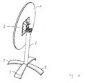
- the selected as an exemplary folding table according to Figure 1 consists of a round table top 1 which is attached to a table leg 2 hinged.
- On the table leg 2 Aufstellfee 3 are provided on the side facing away from the table top 1 side.
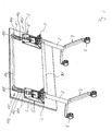
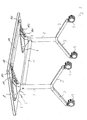
- a rectangular table top 1 ' is provided, which is hingedly attached to two legs table 2.
- the table legs 2 are connected to each other in the embodiments according to Figures 2 and 3 by a crossbar 21.
- On the table legs 2 Aufstellfozoe 3 are provided, which are provided in the embodiment at their legs facing away from the legs 2 with rollers 4.
- a device 5 for folding the table tops 1, 1' is arranged between them and the table legs 2. Since two table legs 2 are provided in the embodiment according to Figures 2 and 3, two devices 5 for folding the table top 1 'are provided.
- the device 5 consists essentially of plastic.
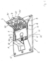
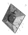
- the device 5 consists essentially of a base plate 6 and a pivotable in the base plate mounted table leg recording 7. Base plate 6 and table leg 7 are made of plastic.
- the base plate 6 has substantially the shape of a truncated pyramid with a rectangular plan. In a modification of the embodiment, the base plate 6 may also be square. The square design is used in particular for round folding tables, as can be seen in FIG.
- the base plate 6 is provided with holes 61, which serve for the passage of - not shown - screws for attachment to the table top.
- the holes 61 are provided on all four sides of the outline of the base plate 6; in the base plates with a rectangular basic shape, the holes 61 are usually provided only on the end faces.
- a square recess 62 is formed in the center of the base plate 6, a square recess 62 is formed.
- webs 63 are provided, which are provided at their free ends with holes.
- guides 621 are provided in the recess.
- Adjacent to the guides 621 holding blocks 622 are provided in the recess 62 on the side facing away from the webs 63 side.
- a mechanism for Verund unlocking of the device is also provided.
- a lever 64 is movably arranged on the base plate 6.
- the lever 64 is under the influence of a coil spring 65, which is attached on the one hand to the lever 64, on the other hand to a wall of the recess.
- the spring 65 is provided at both ends with loops 651, the plates behind hook-shaped web 652 engage.
- holes 66 are provided in the wall of the base plate 6 .
- the lever 64 has a base 641, followed by locking 642 on two sides.
- the latches 642 have an L-shaped cross-section, wherein the horizontal leg is arranged on the side facing away from the base plate 6. In the idle state, the latches 642 are arranged in sections below the holding blocks 622.
- To the locks 642 follow bolt-shaped portions 643 having at their ends perpendicularly oriented guide rods 644. Through the longitudinal center line of the bolt-shaped portions 643, the tilt axis of the lever 64 extends.
- a linkage 10 is provided as a mechanism for locking and unlocking the device instead of the lever 64 on the base plate 6.
- the linkage 10 has two push rods 101, which protrude beyond the base plate 6.
- the pushrods 101 are guided on their sides remote from the base plate 6 in tunnel-like projections 102, which are provided on mounting plates 103.
- the mounting plates 103 are bolted to the table top 1 '.
- the push rods 101 are articulated to an actuating rod 104, which is mounted in tube-shaped receptacles 105, which are connected to the mounting plates 103.
- the receptacles 105 are movable relative to the mounting plates 103.
- About the linkage 10 is a synchronization of the two devices 5 on the table top 1 '.
- the table leg receptacle 7 has a square shape. It is provided on its one side with webs 71, which are provided at their free ends with holes. In the assembled state, the webs 71 are arranged offset to the webs 63 of the base plate 6. The holes provided in the webs 63 and 71 are aligned in the assembled state. In the assembled state, the holes take on a hinge pin 8 which is mounted in the bores 66 of the base plate 6. The holes 66 then form the hinge bearing of the device.
- Adjacent to the webs 71 7 holes 72 are arranged in the table leg recording, which are provided for the rotatable mounting of guide arms 73.
- the guide arms 73 have at their one end a sleeve 731 which is arranged at right angles to the guide arm 73 and which is received in the mounted state by the bore 72.
- a round guide stump 732 is provided, which is also at right angles to the guide arm 731 is aligned and in the assembled state in the guides 621 of the recess 62, the base plate 6 is guided.
- L-shaped locking hooks 74 are arranged on the table leg receptacle 7 in cross section. Due to their L-shaped design, the locking hooks 74 are provided at their base plate 6 end facing with projections 741.
- the projections 741 have run-on slopes 742 at their free ends.
- the table leg holder 7 On its side facing away from the base plate 6, the table leg holder 7 is equipped with a circular recess 75 in the exemplary embodiment.
- the recess 75 receives a receiving ring 76 in the assembled state, the outer diameter of the clear width of the recess 75 corresponds;
- the inner diameter of the receiving ring 76 corresponds to the clear width of the table legs 2.
- the receiving ring 76 may have different inner diameter with the same outer diameter, whereby an adaptation to table legs of different diameters is possible.
- the receiving ring 76 has on one side a radially oriented, rectangular cut 761, which corresponds in the assembled state with a sliding block 9 and secures the ring 76 against rotation.
- the table leg receptacle 7 On the side facing away from the webs 71, the table leg receptacle 7 is provided with a plug 77 made of rubber, which is held clamped in an opening 78. The plug 77 serves as a buffer when folding the tables to avoid damage.
- the sliding block 9 has on its side facing the table leg 7 side in the exemplary embodiment, two pins 91 which - not shown - holes in the table holder 7 and with which the nut 9 is held in the table leg holder 7 under interference fit.
- the unlocking of base plate 6 and table leg 7 is required.
- the lever 64 or the linkage 10 is operated against the force of the spring 65.
- the latches 642 arranged adjacent to the base 641 are moved in the direction away from the respective table leg 2.
- the latches 642 thus release the projections 741 of the locking hooks 74, so that the table leg receptacle 7 is unlocked from the base plate 6.
- the base plate 6 is pivotable about the axis of rotation of the hinge pin 8 through the longitudinal center line of the hinge pin 8 in this state. In the outermost position, provided on the guide arms 73 guide stumps 732 fall into the recess 62. This prevents accidental folding back of the table top 1, 1 ', since the free ends of the guide arms 73 with the guide stumps 732 at the bottom of the recess 62 and supported on the guide rods 644.
- the table top 1, 1 'with base plate 6 in a simple manner in the direction of the table leg receptacle 7 around the hinge pin 8 is folded.
- the actuation of the lever 64 and the linkage 10 is also necessary.
- the free ends of the guide rods 644 are raised.
- the guide arms 73 are raised with the guide stumps 732 so that they emerge from the recess.
- the guide stumps 732 then slide along the guides 621 until the locking hooks 74 come to rest on the lever 64 with their stop bevels 742 provided on the projections 741 with the latches 642.
- the lever 64 or the linkage 10 with the latches 642 back so that the projections 741 with the chamfers 742 pass through the latches 642.
- the lever 64 or the linkage 10 After passing through the latches 642, the lever 64 or the linkage 10 returns under the influence of the spring 65 to its original position.
- the latches 642 then grip with their horizontal legs on the projections 741, so that the base plate 6 is locked to the table holder 7. Due to the partial positioning of the latches 642 under holding blocks 622 unintentional folding of the table top 1, 1 'is prevented.
Landscapes
- Tables And Desks Characterized By Structural Shape (AREA)
Applications Claiming Priority (1)
| Application Number | Priority Date | Filing Date | Title |
|---|---|---|---|
| DE200620003535 DE202006003535U1 (de) | 2006-03-03 | 2006-03-03 | Vorrichtung zum Klappen einer Tischplatte |
Publications (2)
| Publication Number | Publication Date |
|---|---|
| EP1829461A2 true EP1829461A2 (fr) | 2007-09-05 |
| EP1829461A3 EP1829461A3 (fr) | 2008-02-27 |
Family
ID=36746409
Family Applications (1)
| Application Number | Title | Priority Date | Filing Date |
|---|---|---|---|
| EP07000052A Withdrawn EP1829461A3 (fr) | 2006-03-03 | 2007-01-03 | Dispositif pour plateau de table escamotable |
Country Status (2)
| Country | Link |
|---|---|
| EP (1) | EP1829461A3 (fr) |
| DE (1) | DE202006003535U1 (fr) |
Cited By (5)
| Publication number | Priority date | Publication date | Assignee | Title |
|---|---|---|---|---|
| EP2238862A1 (fr) * | 2009-04-09 | 2010-10-13 | Steelcase Werndl Aktiengesellschaft | Table pliante |
| USD879514S1 (en) | 2018-04-16 | 2020-03-31 | Playground Store Limited | Desk |
| USD895325S1 (en) | 2018-04-16 | 2020-09-08 | Playground Store Limited | Desktop with stowed legs |
| US11051611B2 (en) | 2018-04-16 | 2021-07-06 | Playground Store Limited | Desk system |
| US12070123B2 (en) | 2022-11-16 | 2024-08-27 | Lakeshore Learning Materials, Llc | Table with rotating tabletop |
Families Citing this family (11)
| Publication number | Priority date | Publication date | Assignee | Title |
|---|---|---|---|---|
| EP1958537B1 (fr) | 2007-02-19 | 2014-04-30 | Pro-Cord S.p.A. | Table qui se plie et qui s'emboîte |
| EP2187778A2 (fr) * | 2007-09-11 | 2010-05-26 | Gentas Genel Metal Sanayi Ve Ticaret Anonim Sirketi | Mécanisme de table pliante |
| DE202010016726U1 (de) | 2010-12-17 | 2011-03-10 | Von der Mühlen, Roland | Vorrichtung zur Befestigung einer Tischplatte |
| DE202011100450U1 (de) | 2011-05-09 | 2011-07-06 | von der Mühlen, Roland, 58256 | Vorrichtung zum Klappen einer Tischplatte |
| DE202011101307U1 (de) | 2011-05-24 | 2011-11-02 | Roland von der Mühlen | Vorrichtung zur lösbaren Befestigung von Tischbeinen |
| DE202012102372U1 (de) | 2012-06-27 | 2012-08-21 | Roland von der Mühlen | Vorrichtung zur klappbaren Befestigung von Tischbeinen |
| EP2796071A1 (fr) * | 2013-04-23 | 2014-10-29 | Yotrio Group Co., Ltd. | Table pliante |
| DE202014101396U1 (de) | 2014-03-25 | 2014-04-17 | Roland von der Mühlen | Vorrichtung zum Klappen einer Tischplatte |
| WO2020035809A1 (fr) * | 2018-08-16 | 2020-02-20 | Fleetwood Group, Inc. | Ensemble de verrous de meuble pliant |
| IT201800009630A1 (it) * | 2018-10-19 | 2020-04-19 | Pedrali Spa | Attuatore mobile per attuare un telaio pieghevole per il ribaltamento di un piano di appoggio di un tavolo |
| FR3088181B1 (fr) * | 2018-11-08 | 2021-01-22 | Lafuma Mobilier Sas | Piece d’articulation pour table |
Family Cites Families (5)
| Publication number | Priority date | Publication date | Assignee | Title |
|---|---|---|---|---|
| US3993004A (en) * | 1974-12-11 | 1976-11-23 | Johnson Industries | Removable and tiltable table top |
| US4643105A (en) * | 1985-03-13 | 1987-02-17 | Berco Industries, Inc. | Table top support |
| US4986195A (en) * | 1988-09-28 | 1991-01-22 | Howe Furniture Corporation | Tilting table top mechanism |
| US5121697A (en) * | 1991-07-25 | 1992-06-16 | Berco Industries | Flip top table |
| FR2866792B1 (fr) * | 2004-03-01 | 2007-08-31 | Philippe Hurel | Table a plateau basculant et amovible |
-
2006
- 2006-03-03 DE DE200620003535 patent/DE202006003535U1/de not_active Expired - Lifetime
-
2007
- 2007-01-03 EP EP07000052A patent/EP1829461A3/fr not_active Withdrawn
Cited By (6)
| Publication number | Priority date | Publication date | Assignee | Title |
|---|---|---|---|---|
| EP2238862A1 (fr) * | 2009-04-09 | 2010-10-13 | Steelcase Werndl Aktiengesellschaft | Table pliante |
| US8291830B2 (en) | 2009-04-09 | 2012-10-23 | Steelcase Werndl Ag | Folding table |
| USD879514S1 (en) | 2018-04-16 | 2020-03-31 | Playground Store Limited | Desk |
| USD895325S1 (en) | 2018-04-16 | 2020-09-08 | Playground Store Limited | Desktop with stowed legs |
| US11051611B2 (en) | 2018-04-16 | 2021-07-06 | Playground Store Limited | Desk system |
| US12070123B2 (en) | 2022-11-16 | 2024-08-27 | Lakeshore Learning Materials, Llc | Table with rotating tabletop |
Also Published As
| Publication number | Publication date |
|---|---|
| DE202006003535U1 (de) | 2006-07-13 |
| EP1829461A3 (fr) | 2008-02-27 |
Similar Documents
| Publication | Publication Date | Title |
|---|---|---|
| EP1854373A2 (fr) | Système de table | |
| DE202006003535U1 (de) | Vorrichtung zum Klappen einer Tischplatte | |
| DE202014101396U1 (de) | Vorrichtung zum Klappen einer Tischplatte | |
| EP1159887B1 (fr) | Table pliable | |
| DE19741743C2 (de) | Klapptischbeschlag | |
| EP1279352B1 (fr) | Table pliante | |
| DE202012009964U1 (de) | Klapptisch | |
| DE69903078T2 (de) | Verschiebbarer Tragpfosten für Planendächer für Fahrzeugaufbauten | |
| DE102012201204B4 (de) | Verriegelungssystem für eine Tischtennisplatte | |
| DE202007002775U1 (de) | Tischmöbel mit schwenkbarer Tischplatte | |
| DE10329036B4 (de) | Verriegelungssystem für Spielhälften eines Tischtennisspieles | |
| EP0446623B1 (fr) | Support pliant pour supporter des dessus de tables, des boîtes à outils et similaire | |
| AT524026A4 (de) | Tisch mit mehreren Tischplatten | |
| EP2640557B1 (fr) | Table de travail, en particulier pour les ateliers | |
| DE102020212967B3 (de) | Verriegelungseinrichtung, höhenverstellbarer Tisch mit der Verriegelungseinrichtung, Fahrzeug mit dem höhenverstellbaren Tisch und Verfahren zum Verriegeln des höhenverstellbaren Tischs | |
| DE202011100450U1 (de) | Vorrichtung zum Klappen einer Tischplatte | |
| DE102004054934B3 (de) | Klapptisch | |
| EP0457247A1 (fr) | Chariot de transport pour tables d'opération | |
| EP3819422B1 (fr) | Articulation et séchoir à linge doté d'une telle articulation | |
| DE10332394B4 (de) | Verriegelungssystem für zwei Spielhälften eines Tischtennisspieles | |
| DE102005001062B4 (de) | Anordnung zur Verriegelung eines Tischtennistisches | |
| EP2286690A1 (fr) | Table variable | |
| DE202013005787U1 (de) | Klappbarer Garten- und Freizeittisch | |
| DE102014014310B4 (de) | Klappgestell für Bänke oder Tische | |
| DE4418687C2 (de) | Zusammenklappbarer Arbeitstisch, insbesondere Spanntisch |
Legal Events
| Date | Code | Title | Description |
|---|---|---|---|
| PUAI | Public reference made under article 153(3) epc to a published international application that has entered the european phase |
Free format text: ORIGINAL CODE: 0009012 |
|
| AK | Designated contracting states |
Kind code of ref document: A2 Designated state(s): AT BE BG CH CY CZ DE DK EE ES FI FR GB GR HU IE IS IT LI LT LU LV MC NL PL PT RO SE SI SK TR |
|
| AX | Request for extension of the european patent |
Extension state: AL BA HR MK YU |
|
| PUAL | Search report despatched |
Free format text: ORIGINAL CODE: 0009013 |
|
| AK | Designated contracting states |
Kind code of ref document: A3 Designated state(s): AT BE BG CH CY CZ DE DK EE ES FI FR GB GR HU IE IS IT LI LT LU LV MC NL PL PT RO SE SI SK TR |
|
| AX | Request for extension of the european patent |
Extension state: AL BA HR MK YU |
|
| AKX | Designation fees paid | ||
| STAA | Information on the status of an ep patent application or granted ep patent |
Free format text: STATUS: THE APPLICATION IS DEEMED TO BE WITHDRAWN |
|
| 18D | Application deemed to be withdrawn |
Effective date: 20080828 |
|
| REG | Reference to a national code |
Ref country code: DE Ref legal event code: 8566 |