EP1830046A2 - Unité d'entraînement dotée d'un gain de retour de chaleur - Google Patents
Unité d'entraînement dotée d'un gain de retour de chaleur Download PDFInfo
- Publication number
- EP1830046A2 EP1830046A2 EP07003533A EP07003533A EP1830046A2 EP 1830046 A2 EP1830046 A2 EP 1830046A2 EP 07003533 A EP07003533 A EP 07003533A EP 07003533 A EP07003533 A EP 07003533A EP 1830046 A2 EP1830046 A2 EP 1830046A2
- Authority
- EP
- European Patent Office
- Prior art keywords
- cooling circuit
- cooling
- working fluid
- drive unit
- heat
- Prior art date
- Legal status (The legal status is an assumption and is not a legal conclusion. Google has not performed a legal analysis and makes no representation as to the accuracy of the status listed.)
- Granted
Links
Images


Classifications
-
- F—MECHANICAL ENGINEERING; LIGHTING; HEATING; WEAPONS; BLASTING
- F01—MACHINES OR ENGINES IN GENERAL; ENGINE PLANTS IN GENERAL; STEAM ENGINES
- F01P—COOLING OF MACHINES OR ENGINES IN GENERAL; COOLING OF INTERNAL-COMBUSTION ENGINES
- F01P7/00—Controlling of coolant flow
- F01P7/14—Controlling of coolant flow the coolant being liquid
- F01P7/16—Controlling of coolant flow the coolant being liquid by thermostatic control
- F01P7/165—Controlling of coolant flow the coolant being liquid by thermostatic control characterised by systems with two or more loops
-
- F—MECHANICAL ENGINEERING; LIGHTING; HEATING; WEAPONS; BLASTING
- F02—COMBUSTION ENGINES; HOT-GAS OR COMBUSTION-PRODUCT ENGINE PLANTS
- F02B—INTERNAL-COMBUSTION PISTON ENGINES; COMBUSTION ENGINES IN GENERAL
- F02B29/00—Engines characterised by provision for charging or scavenging not provided for in groups F02B25/00, F02B27/00 or F02B33/00 - F02B39/00; Details thereof
- F02B29/04—Cooling of air intake supply
- F02B29/0406—Layout of the intake air cooling or coolant circuit
- F02B29/0412—Multiple heat exchangers arranged in parallel or in series
-
- F—MECHANICAL ENGINEERING; LIGHTING; HEATING; WEAPONS; BLASTING
- F02—COMBUSTION ENGINES; HOT-GAS OR COMBUSTION-PRODUCT ENGINE PLANTS
- F02B—INTERNAL-COMBUSTION PISTON ENGINES; COMBUSTION ENGINES IN GENERAL
- F02B29/00—Engines characterised by provision for charging or scavenging not provided for in groups F02B25/00, F02B27/00 or F02B33/00 - F02B39/00; Details thereof
- F02B29/04—Cooling of air intake supply
- F02B29/0406—Layout of the intake air cooling or coolant circuit
- F02B29/0437—Liquid cooled heat exchangers
- F02B29/0443—Layout of the coolant or refrigerant circuit
-
- F—MECHANICAL ENGINEERING; LIGHTING; HEATING; WEAPONS; BLASTING
- F02—COMBUSTION ENGINES; HOT-GAS OR COMBUSTION-PRODUCT ENGINE PLANTS
- F02M—SUPPLYING COMBUSTION ENGINES IN GENERAL WITH COMBUSTIBLE MIXTURES OR CONSTITUENTS THEREOF
- F02M26/00—Engine-pertinent apparatus for adding exhaust gases to combustion-air, main fuel or fuel-air mixture, e.g. by exhaust gas recirculation [EGR] systems
- F02M26/02—EGR systems specially adapted for supercharged engines
- F02M26/08—EGR systems specially adapted for supercharged engines for engines having two or more intake charge compressors or exhaust gas turbines, e.g. a turbocharger combined with an additional compressor
-
- F—MECHANICAL ENGINEERING; LIGHTING; HEATING; WEAPONS; BLASTING
- F02—COMBUSTION ENGINES; HOT-GAS OR COMBUSTION-PRODUCT ENGINE PLANTS
- F02M—SUPPLYING COMBUSTION ENGINES IN GENERAL WITH COMBUSTIBLE MIXTURES OR CONSTITUENTS THEREOF
- F02M26/00—Engine-pertinent apparatus for adding exhaust gases to combustion-air, main fuel or fuel-air mixture, e.g. by exhaust gas recirculation [EGR] systems
- F02M26/13—Arrangement or layout of EGR passages, e.g. in relation to specific engine parts or for incorporation of accessories
- F02M26/22—Arrangement or layout of EGR passages, e.g. in relation to specific engine parts or for incorporation of accessories with coolers in the recirculation passage
- F02M26/23—Layout, e.g. schematics
- F02M26/28—Layout, e.g. schematics with liquid-cooled heat exchangers
-
- F—MECHANICAL ENGINEERING; LIGHTING; HEATING; WEAPONS; BLASTING
- F01—MACHINES OR ENGINES IN GENERAL; ENGINE PLANTS IN GENERAL; STEAM ENGINES
- F01P—COOLING OF MACHINES OR ENGINES IN GENERAL; COOLING OF INTERNAL-COMBUSTION ENGINES
- F01P2050/00—Applications
- F01P2050/02—Marine engines
- F01P2050/06—Marine engines using liquid-to-liquid heat exchangers
-
- F—MECHANICAL ENGINEERING; LIGHTING; HEATING; WEAPONS; BLASTING
- F01—MACHINES OR ENGINES IN GENERAL; ENGINE PLANTS IN GENERAL; STEAM ENGINES
- F01P—COOLING OF MACHINES OR ENGINES IN GENERAL; COOLING OF INTERNAL-COMBUSTION ENGINES
- F01P2060/00—Cooling circuits using auxiliaries
- F01P2060/02—Intercooler
-
- F—MECHANICAL ENGINEERING; LIGHTING; HEATING; WEAPONS; BLASTING
- F01—MACHINES OR ENGINES IN GENERAL; ENGINE PLANTS IN GENERAL; STEAM ENGINES
- F01P—COOLING OF MACHINES OR ENGINES IN GENERAL; COOLING OF INTERNAL-COMBUSTION ENGINES
- F01P3/00—Liquid cooling
- F01P3/22—Liquid cooling characterised by evaporation and condensation of coolant in closed cycles; characterised by the coolant reaching higher temperatures than normal atmospheric boiling-point
-
- Y—GENERAL TAGGING OF NEW TECHNOLOGICAL DEVELOPMENTS; GENERAL TAGGING OF CROSS-SECTIONAL TECHNOLOGIES SPANNING OVER SEVERAL SECTIONS OF THE IPC; TECHNICAL SUBJECTS COVERED BY FORMER USPC CROSS-REFERENCE ART COLLECTIONS [XRACs] AND DIGESTS
- Y02—TECHNOLOGIES OR APPLICATIONS FOR MITIGATION OR ADAPTATION AGAINST CLIMATE CHANGE
- Y02T—CLIMATE CHANGE MITIGATION TECHNOLOGIES RELATED TO TRANSPORTATION
- Y02T10/00—Road transport of goods or passengers
- Y02T10/10—Internal combustion engine [ICE] based vehicles
- Y02T10/12—Improving ICE efficiencies
Definitions
- the invention relates to a drive unit of a motor vehicle, which has an internal combustion engine, via a low-pressure compressor, a high-pressure compressor and a charge air cooling unit having charge air supply and via an exhaust discharge, is discharged by means of formed in the internal combustion engine exhaust gas. Furthermore, a cooling system with at least one cooling circuit is provided, in which a throughput of a working fluid and coolable by ambient air heat exchanger, at least one integrated into the exhaust gas discharge exhaust gas cooler and the charge air cooling unit are arranged.
- the charge air cooling unit in this case has a charge air intercooler and a charge air main cooler, which are thermally coupled to the at least one cooling circuit such that in the flow direction of the charge air of the charge air intercooler between the low pressure and the high pressure compressor is arranged and the charge air main cooler is connected downstream of the high pressure compressor.
- the water cooling has largely prevailed.
- the cylinder head and the cylinder crankcase are usually double-walled, with the water jacket is located between this wall, with which the heat of combustion of the engine is dissipated.
- the cooling circuit is composed of water pump, thermostat, connecting hoses, radiator, expansion tank and fan.
- the coolant used is a mixture of water and 30-50% antifreeze and corrosion inhibitor, usually ethylene glycol.
- the coolant fulfills the task of corrosion protection, raising the boiling temperature and prevention of freezing of the cooling circuit.
- cooling systems for motor vehicles are known in which different working fluids are used within the cooling system.
- a cooling system for liquid-cooled internal combustion engines which additionally has a heat buffer, which is coupled via a heat exchanger unit to the first cooling circuit.
- the heat buffer cooling system is intended to ensure that the sizing of the coolant and the air-liquid heat exchanger can be tailored to normal operation needs while still maintaining adequate heat dissipation during peak load requirements.
- the heat buffer contains a heat storage medium, which is in heat exchange with the cooling liquid of the cooling circuit.
- the heat storage medium is selected such that it is in the upper operating temperature range of the coolant, but not more than 10 K above the maximum permissible operating temperature, a phase transition passes. Exceeds the operating temperature of the coolant, the evaporation temperature of the storage medium in the heat storage, the coolant is withdrawn by the significant phase transition, a significant amount of heat and thus prevents the complete completion of the phase transition further heating of the coolant.
- the cooling system described essentially has a generator in which the ammonia evaporates from the water-ammonia mixture, via a phase separator in which the liquid is separated from the vapor phase, via a condenser in which the ammonia is re-liquefied and via a throttle valve with downstream further evaporator and finally via an absorber in which the gaseous ammonia is dissolved in the water with release of heat.
- the heat to be dissipated from the region of the engine in the generator is transferred to the ammonia-water mixture and used with the aid of the capacitor for fuel heating.
- a cooling system for motor vehicle engines with intercooling known in which two air-cooled heat exchanger and a charge air cooler are provided in a cooling circuit.
- a cooling system with a unit cooling circuit for cooling an internal combustion engine comprising a main cooling circuit with main coolant radiator and an additional cooling circuit for cooling an additional medium, the additional cooling circuit branches off at a coupling point of the main cooling circuit and to this at a coupling point, which is arranged between the main coolant radiator and a coolant pump is, leads back.
- a charge air cooler is provided, with which the charge air supplied to the internal combustion engine is cooled.
- the cooling circuits can be operated at different temperature levels and the coolant delivery pump can be adjusted with regard to the volume flow to be conveyed, the delivery rate and / or the delivery pressure.
- the present invention seeks to provide a cooling system for a drive unit of a motor vehicle with an internal combustion engine, which allows the efficient removal of heat from the drive unit and at the same time ensures that the heat other vehicle components before or during the driving operation must be heated, is provided. In this case, particular care must be taken that even with different operating conditions of the motor vehicle as effective as possible heat transfer between the various vehicle components is made possible without this driving power is lost.
- the invention relates to a drive unit of a motor vehicle, which has an internal combustion engine, via a low-pressure compressor, a high-pressure compressor and a charge air cooling unit having charge air supply and via an exhaust discharge, is discharged by means of formed in the internal combustion engine exhaust gas. Furthermore, a cooling system with at least one cooling circuit is provided, in which a throughput of a working fluid and coolable by ambient air heat exchanger, at least one integrated into the exhaust gas discharge exhaust gas cooler and the charge air cooling unit are arranged.
- the charge air cooling unit in this case has a charge air intercooler and a charge air main cooler, which are thermally coupled to the at least one cooling circuit such that in the flow direction of the charge air of the charge air intercooler between the low pressure and the high pressure compressor is arranged and the charge air main cooler is connected downstream of the high pressure compressor.
- the drive unit has been developed such that at least one first cooling circuit and at least one second cooling circuit are provided, which are hydraulically decoupled by means of at least one heat exchanger, via which the first and the second cooling circuit are in thermal contact, and In an operating medium contained in the second cooling circuit during an operating phase of the cooling system, an at least partial phase transition can be brought about.
- the essential idea here is that the heat energies provided by the heat sources provided in the drive unit of a motor vehicle at different temperature levels are effectively utilized by a temperature-adapted interconnection of these components and corresponding heat exchangers, by using the largest possible amount of heat energy within the drive unit or for corresponding ancillary units not released unused to the environment.
- at least one cooling circuit is provided, in which a working medium is heated in such a way that at least a partial phase transition is brought about in this working medium.
- An integral part of the invention is that both the costs incurred in the intercooler and in the exhaust system heat via the connection to a cooling circuit, in which at least temporarily a vaporous working fluid is included, is made available again for the drive unit and the aforementioned ancillaries.
- a heat recovery at the exhaust gas recirculation over which the charge air is at least partially admixed with exhaust gas, and / or at a location which is located, for example, downstream of the exhaust gas turbocharger can be realized.
- further heat sources such as an oil cooler or a retarder, fuel cooler can be integrated.
- the first cooling circuit is an engine cooling circuit in which the heat accumulating in the internal combustion engine is at least partially removed. It is equally conceivable to make use of the heat to be dissipated in charge air and / or exhaust gas cooling via the engine cooling circuit or one or more additional cooling circuits.
- a first working fluid is provided in the first cooling circuit and a second working fluid is provided in the second cooling circuit, the first and the second working fluid differing in their chemical and / or physical properties.
- the second working fluid in the second cooling circuit has an evaporation point or an evaporation temperature that is lower than the evaporation temperature of the first working fluid.
- the working medium conveyed in the second cooling circuit is a mixture of at least two working component components, of which at least one component has an evaporation temperature which is lower than the evaporation temperature of the working medium conveyed in the first cooling circuit.
- the first and the second cooling circuit are operated at different pressure and / or temperature levels.
- a very specific embodiment of the proposed cooling system provides that in the second cooling circuit, an ammonia-water mixture is promoted.
- This mixture is characterized in particular by the fact that ammonia (NH 3 ) has an evaporation temperature which is far below the evaporation temperature of water in the cooling systems of motor vehicles usually prevailing pressures.
- ammonia evaporates at about -33 ° C (about 240 K).
- the cooling system according to the invention it is possible with the cooling system according to the invention to use the heat in the second cooling circuit for certain, provided in the drive unit or ancillaries heat sinks, such as vehicle heaters or air conditioning. Furthermore, it is conceivable to convert this heat or the energy, which is preferably stored in the working medium vapor, into mechanical work, for example in the form of rotational energy. In this way, it is even possible to convert this energy into electrical energy.
- the working medium located in the second working group is at least partially converted into a vapor phase, it is conceivable, for example, to supply this vapor to an expansion unit, so that the energy contained in the steam can be converted into corresponding kinetic energy.
- a very specific embodiment of the invention also provides that the kinetic energy provided by the expansion unit is used to drive the internal combustion engine.
- a mechanical connection between an output shaft of the expansion unit and the internal combustion engine by means of corresponding coupling elements, such as crankshaft (in the manner of a reverse air compressor principle), gear drive or belt drive is made.
- a very special technical solution even provides for a direct connection of the expansion unit to the drive unit.
- the expansion unit has steam-operated pistons, so that the mechanical energy provided by the expansion machine can be transmitted to the drive unit by means of corresponding connecting rod connections or push rods.
- the steam present in the second cooling circuit before it is supplied to the expansion unit, which may be a piston engine, an expander or a turbine, is separated from the liquid phase of the working fluid in a separator unit , Is, as previously mentioned, an ammonia-water mixture used as a working fluid in the second cooling circuit, the liquid phase containing a large proportion of water is separated from the vaporous ammonia phase in the separator.
- the working fluid After the working fluid has been expanded in the expansion unit, it is preferably fed to a condenser in which it is re-liquefied with the release of heat.
- the working medium is a multi-component working medium, wherein at least only one of the components has entered the vapor phase, a mixing with the liquid constituents of the working medium takes place after the condensation of the hitherto vaporous working medium. In this way, a liquid working fluid is made available again, which is finally back to the heat exchanger of the second cooling circuit, which is thermally in communication with the first cooling circuit, is promoted.
- further components such as throttle and / or control valves, as well as to arrange further heat exchangers, for example for removing the heat arising during the absorption of a substance, within the second cooling circuit.
- a further very specific embodiment of the invention provides in the second cooling circuit a delivery unit for the working medium, which is operated as a function of a stored in a motor control operating point or operating map. It is conceivable, for example, to use a pump or a compressor whose / whose speed is adjustable and thus the amount of steam provided in the second cooling circuit is adjustable. Depending on the operating state and controlled variable, the amount of steam provided, in particular the volumetric flow, and / or the pressure prevailing in the second cooling circuit are varied. In particular, the control of the pressure prevailing in the second cooling circuit allows the provision of different amounts of steam and the relaxation of the generated steam to a demand-adjusted pressure level. It is equally possible, of course, to adapt the volume flow of the conveyed working medium, in particular the steam volume flow, in the second cooling circuit to the operating requirements via the controllable conveying unit described above.
- a working medium consisting of at least two components in the second cooling circuit
- a hydrocarbon compound with a low boiling or vaporization temperature as the working medium.
- Butane and pentane compounds are particularly suitable in this context.
- Another suitable particularly for use as a working medium in the second cooling circuit medium represents n-perfluoro-pentane (C 5 F 12).
- the latter working medium is characterized here in particular by the fact that it represents a non-flammable so-called safety refrigerant.
- the method according to the invention also ensures that the heat provided in the region of a motor vehicle drive unit by various heat sources, such as charge air cooler or exhaust gas recirculation, is made available for further applications without this heat being dissipated exclusively to the environment.
- various heat sources such as charge air cooler or exhaust gas recirculation
- a first working fluid and circulated in a second cooling circuit a second working fluid and from the charge air and / or the exhaust gas, preferably via the heat exchanger exhaust gas recirculation, heat dissipated to that in the first cycle subsidized working fluid or heat stored in the first working fluid, at least partially transmitted to the second working fluid conveyed in the second cooling circuit.
- the two cooling circuits are operated separately, which means that in each case at least one delivery unit is provided in both cooling circuits.
- the first and the second cooling circuit can be operated as required, that is to say in particular as a function of the quantities of heat to be dissipated.
- a working fluid is used in the second cooling circuit, at least partially due to the transfer of heat directly from the charge air and / or exhaust gas cooling in the second cooling circuit and / or indirectly by heat transfer from the first into the second cooling circuit in a steam or gaseous phase is convertible.
- the second cooling circuit In the second cooling circuit, evaporation, relaxation, liquefaction and renewed evaporation of the working medium thus alternate depending on the heat or energy requirement.
- the expansion unit which is at a turbine or a correspondingly designed expander unit
- the heat energy contained in the steam is converted into moving, preferably rotational, energy.
- This kinetic energy can, for example, be transmitted, as it were, as drive assistance for increasing the overall system efficiency to the internal combustion engine.
- By providing a generator it is further preferably possible to convert the rotational energy into electrical energy which is made available to the motor vehicle or electrical consumers of the motor vehicle.
- the rotational energy provided by the expansion unit as it were, as drive energy for other systems.
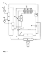
- the cooling circuit 1 shown in FIG. 1 is subdivided essentially into two hydraulically connected main flow paths.
- the flow paths differ essentially by the temperature level at which they are operated. So it is a high-temperature 2 and the low-temperature flow path 3, in which a working fluid is circulated at a different temperature.
- each air-liquid heat exchanger 4, 5 are provided, which are cooled by means of ambient air.
- a working medium is conveyed via the coolant supply pump 6, which has two components.
- the working fluid is a mixture of water and a glycol, wherein the glycol raises the evaporation temperature of the mixture compared to pure water, prevents corrosion within the cooling circuit 1 and also prevents the freezing of the cooling circuit at low outdoor temperatures and vehicle life.
- the coolant delivery pump 6 promotes, as soon as it is turned on, depending on the engine speed, a constant amount of coolant or working fluid through the coolant circuit 1.
- Within the cooling circuit control valves 7, 8 are provided by means of which the flow rate of the working fluid through the different flow paths of the coolant circuit 1 is adjustable. In this way, the flow rate of the working fluid, which flows through the high-temperature cooler 4, the low-temperature cooler 5 and the exhaust gas cooler 9, which is here an exhaust gas recirculation cooler, can be regulated.
- the compression of the charge air is in this case carried out in two stages in order to cool the charge air in a between the low pressure 11 and the high pressure compressor 12 arranged charge air intercooler 13th to maximize the efficiency of charge air compression.
- the charge air leaving the high-pressure compressor 12 has a temperature of about 170 ° C. (about 443 K) at a pressure of about 3 ⁇ 10 5 Pa.
- the charge air is cooled to a temperature of about 45 ° C (about 318 K).
- a charge air intercooler 13 and as a charge air main radiator 14 each liquid-air heat exchanger are provided in which the heat dissipated from the compressed charge air heat is transferred to the located in the low-temperature circuit 3 working fluid.
- the charge air After the charge air has left the charge-air main cooler 14, it is admixed with part of the exhaust gas which has already left the brake engine 10, and this exhaust-charge air mixture is supplied to the combustion chamber of the internal combustion engine 10.
- the proportion of the charge air admixed exhaust gas may be 20 to 40% of the engine exhaust gas leaving the exhaust.
- the internal combustion engine 10 is further downstream of an exhaust gas recirculation exhaust cooler 9, with which the part of the exhaust gas, which is mixed with the charge air, is cooled.
- the resulting heat in the exhaust gas cooler 9 is transmitted via a corresponding heat transfer unit to the funded in the high-temperature circuit 2 working fluid.
- the exhaust gas cooler 9 is arranged such that the exhaust gas cooler 9 and the heat transfer unit in the exhaust gas cooler 9 leaving working fluid flows to the air-cooled high-temperature cooler 4.
- the flow rate of the working medium flowing through the high-temperature cooler 4 is set via the control valve 8 through the flow rate of the working fluid flowing through the exhaust gas cooler 9 or its heat transfer unit.
- the flow rate of the working fluid can be regulated via the control valve 7, which flows through the low-temperature radiator 5 and the parallel-interposed charge air inter-13 and charge-air main radiator 14.
- the control valve 7 which flows through the low-temperature radiator 5 and the parallel-interposed charge air inter-13 and charge-air main radiator 14.
- Such embodiments are explained in more detail in connection with the cooling concepts, which provide at least one cooling circuit in which a working medium at least partially completes a phase transition.
- an oil cooler 24 can be provided, via which the heat to be dissipated from the lubricating oils required for the internal combustion engine enters the high-temperature circuit 2 or the low-temperature circuit 3 is transmitted.
- a cooler may also be an oil cooler of the oil to be cooled for other units of a motor vehicle, such as a retarder, for example, a fuel cooler.
- the cooling system described in FIG. 1 is to be operated such that the working medium conveyed in the low-temperature circuit has a temperature which is 10-15 K below the evaporation temperature of this working medium. Furthermore, a regulation of the working fluid mass flow takes place with regard to the cooling power to be provided by the overall cooling system and / or with regard to an optimal charge air temperature for the combustion process within the internal combustion engine. In order to enable such optimal control of the overall cooling system, corresponding characteristics and maps are stored in the engine control. In this way, a cooling of the charge air and the exhaust gas cooler is made possible taking into account an optimal operating point and / or optimum exhaust gas values of the internal combustion engine.
- a cooling system in which a cooling circuit is provided, in which the working fluid during operation at least partially completes a phase transition.
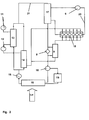
- the first cooling circuit 20 is the cooling circuit of the internal combustion engine (engine cooling circuit).
- a water-glycol mixture is used as a working fluid, which at least partially transfers the heat to be dissipated from the internal combustion engine to the second cooling circuit 21 via the preheater 17.
- a special working fluid is conveyed, which at least partially has a lower evaporation temperature than water or in the first cooling circuit 20 promoted water-glycol mixture.
- the pressure of the working fluid used is after leaving the air-cooled radiator 15 by means of a pump 16 from a pressure of about 1.5 ⁇ 10 5 Pa to a pressure of about 11 to 16 ⁇ 10 5 Pa raised.
- the pump 16 used in this exemplary embodiment is a controllable delivery unit with which a suitable amount of steam and / or a specific pressure in the second cooling circuit 21 can be set as a function of the operating state of the drive unit.
- the pressurized by the pump 16 first working fluid is then by the parallel charge air cooler 13, 14, which may be arranged in an alternative interconnection in series, promoted and reaches at a temperature of about 70 to 90 ° C (about 353 K) a preheater 17 in which the temperature of the working fluid is raised to a temperature of at least about 105 ° C (about 378 K) and at the same time partially evaporated depending on the operating condition.
- the heat required for the preheating of the working fluid in the preheater 17 is provided by the first cooling circuit 20, which dissipates heat from the internal combustion engine.
- the working fluid After leaving the preheater 17, the working fluid enters the exhaust gas cooler 9, wherein the flow rate through the control valve 8 is adjustable.
- the working medium flowing through the exhaust gas cooler 9 is at least partially vaporized or even superheated.
- on the opposite side of the exhaust gas cooler heat exchanger derived from the internal combustion engine 10 exhaust gas of about 650 ° C (about 920 K) to a temperature of about up to 100 ° C. (about 373 K) cooled.
- the working fluid in the exhaust gas cooler 9 After the working fluid in the exhaust gas cooler 9 has been at least partially vaporized, it is conveyed into a separator 18, in which the liquid and the vapor phase of the working fluid are separated from one another. It is irrelevant whether the working medium used is a single-substance working medium or a mixture of several components.
- the working fluid While the liquid part of the working fluid from the separator 18 is passed directly into the air-cooled heat exchanger, which takes over the function of a capacitor 15, is introduced the vapor phase of the working fluid in an expander 19.
- the working fluid In the expander 19, the working fluid is expanded, wherein the energy stored in the working fluid before entering the expander 19 is at least partially converted into kinetic energy.
- an at least partial liquefaction of the working fluid due to the relaxation already takes place within the expander.
- the working fluid is led out of the expander 19 into the air-cooled heat exchanger 15, where a mixing of the fluid streams of the working fluid coming from the expander 19 and from the separator 18 takes place.
- the air-cooled heat exchanger 15 assumes the function of a condenser, in which a complete liquefaction of the working fluid takes place with the release of heat.
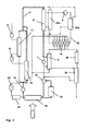
- FIG. 3 shows a further cooling system which differs from the systems described in FIGS. 1 and 2 with regard to the utilization of the heat which is provided by various heat sources present in the region of the motor vehicle drive unit.
- the interconnection of the existing from the compressor units 11, 12 and the intercoolers 13, 14 air supply of the internal combustion engine 10 and the cooling of the exhaust gas recirculation corresponds to the interconnection described in Figures 1 and 2.
- a transmission oil cooler 24b and a motor oil cooler 24a are provided in the first cooling circuit 20, so the so-called engine cooling circuit next to the coolant pump, the dissipated heat is transferred to the funded in the first cooling circuit 20 water-glycol mixture.
- the heat provided in the first cooling circuit is transmitted via the preheater 17 to the second cooling circuit 21, in which, analogously to the embodiment according to FIG. 2, an air-cooled heat exchanger 15, which in turn assumes the function of a capacitor, is arranged.
- the working fluid in the second cooling circuit 21 is heated during the cooling operation such that it performs an at least partial phase transition.
- the working fluid used in the second cooling circuit according to FIGS. 2 and 3 can be a low-evaporation single-substance working fluid or a multi-component mixture, at least one component of the mixture being one with respect to water has comparatively low evaporation temperature.
- the aim of the interconnection shown in FIG. 3 is to provide the largest possible amount of steam in the second cooling circuit 21 through optimal utilization of the heat provided by the various heat sources.
- the energy contained in the amount of steam provided is to be converted into kinetic energy by means of an expander unit.
- two working fluid delivery units 16, 22 are provided whose speed and thus the delivery rate of the working fluid and / or the prevailing pressure in the second cooling circuit 21 is / are variable.
- the first conveying unit 16 is arranged as in FIG. 2, while the additional conveying unit 22 is arranged in a region of the second cooling circuit in which a comparatively low temperature prevails.
- the control of the conveyor units 16, 22 takes place here in dependence on maps that are stored in the engine control unit to realize depending on the respective operating state of the drive unit of the motor vehicle optimized cooling and generation of steam and thus providing kinetic energy.
- the description is based on the air-cooled heat exchanger 15 (vehicle radiator), in which the working fluid that has traveled the separator 18 or the expander 19 has been completely reliquefied.
- a cooling of the working fluid which is realized in one or two stages.
- Another interconnection provides a second low-temperature condenser 23 at this point.
- the working fluid in the high-temperature condenser 15 is first cooled to a temperature of about 80 ° C.
- a first partial flow of the so-tempered working fluid is conveyed via the pump 16 directly into the charge air intercooler 13.
- a second partial flow passes into the low-temperature condenser 23 and is cooled here to a temperature of about 40 ° C.
- the charge air coolers 13, 14 it is merely pointed out that the charge air main 14 and the charge air intercooler 13 can be connected both in parallel and in series.
- the working fluid is conveyed to a preheater 17 and finally evaporated in the exhaust gas cooler 9 or at least partially overheated.
- the working fluid of the second cooling circuit 21 passes into a separator 18, in which the liquid is separated from the vaporous phase of the working fluid.
- the vaporous portion of the working fluid is conveyed to an expander unit 19, in which the working fluid is expanded.
- the relaxed by the expander 19 working fluid passes again into the air-cooled heat exchanger 15 or in accordance with the described alternative interconnection possibly in the low-temperature condenser 23rd
- an exhaust gas heat exchanger 25 is integrated into the second cooling circuit 21.
- the exhaust gas heat exchanger 25 is downstream of the exhaust gas cooler 9 in the flow direction of the working fluid in the second cooling circuit 21 and above all the partial exhaust gas flow, leaving directly the internal combustion engine 1 and only has passed through an exhaust aftertreatment system 26, part of the heat contained in this partial exhaust gas stream and transmits this heat in the second cooling circuit 21.
- the exhaust aftertreatment system 26 may also be arranged in the exhaust gas flow direction in front of the exhaust gas heat exchanger 25.
- the exhaust gas heat exchanger 25 is within the second cooling circuit 21 in the embodiment shown in Figure 3, however, between the exhaust gas cooler 9 and the separator 18th
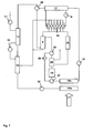
- the cooling system illustrated in FIG. 4 differs from the system shown in FIG. 3 by two features.
- the charge air intercooler 13 and the charge air main cooler 14 are arranged in series, on the other hand, the exhaust gas heat exchanger 26 is in this interconnection between the separator 18 and the expander 19.
- a mixer 27 is provided, in which the separator 18 leaving liquid phase of the working fluid and the expander 19 leaving working fluid are mixed.
- a throttle valve 28 is further provided, via which a relaxation of the working fluid, which does not flow through the expander 19, is achieved.
- FIG. 5 shows a cooling concept in which the air-cooled heat exchanger 15 is formed from a high-temperature condenser 15a and a low-temperature condenser 15b.
- the high-temperature condenser 15a is followed by the delivery unit 16, via which the liquefied working fluid is optionally supplied to the low-temperature condenser 15b and the charge-air main cooler 14 or directly to the charge-air intercooler 13.
- the branch to the low-temperature condenser 15b may be arranged in front of the delivery unit 16 in order to ensure a low pressure in the low-temperature condenser 15b.
- a further mixer 29 is provided in which the working fluid leaving the charge-air main cooler 14 and the preheater 17 is mixed. The preheater 17 is supplied in this case, working fluid, which has flowed through the intercooler 13 intercooler.
- FIG. 6 A comparison with the slightly modified in Fig. 5 cooling system is shown in FIG 6. It is essential here firstly that a diversion to the low-temperature condenser 15b is provided in front of the delivery unit 16, so that a comparatively low pressure is to be ensured in the low-temperature condenser 15b.
- a further conveyor unit 30 downstream of the pressure increase.
- This conveyor unit 30 is variably adjustable.
- the part of the working medium, which leaves the high-temperature condenser 15a and is not passed into the low-temperature condenser 15b is fed via a conveyor unit 16 directly to the pre-heater 17, without flowing through a charge air cooler.
- FIG. 7 a cooling system is shown in FIG. 7, which is modified in such a way that working medium is supplied to the low-temperature condenser 15b by the conveying unit 16 and, on the other hand, the intercoolers 13, 14 are arranged in series behind the low-temperature condenser 15b in the flow direction of the working medium. Basically, a parallel connection of the intercooler is also possible here.
- a partial flow of the working fluid is also conveyed directly from the high-temperature condenser 15a via the conveyor unit 16 in the preheater 17 here. Behind the preheater 17, a mixer 29 is again provided, in which the working fluid leaving the preheater 17 is mixed with the working fluid from the intercoolers 13, 14.
- the cooling systems described in connection with FIGS. 1 to 7 are particularly suitable for use in commercial vehicles. Especially in these vehicles, the need for technical solutions that offer alternatives to conventional cooling concepts, large.
- the mixtures are usually aqueous solutions, in the water, a refrigerant with a low boiling point, ie low evaporation temperature, is dissolved.
- a multi-component working fluid is heated, the component having the low evaporation temperature evaporates, while a largely water-containing aqueous solution remains in the liquid phase.
- ammonia-water mixtures in which ammonia is dissolved in different concentrations in the water.
- Particularly suitable in this context appear ammonia-water mixtures in which the proportion of ammonia in the total mixture is 30, 40 or 50 percent.
- An alternative to the use of the aforementioned multicomponent working fluid is fluid substances which have a comparatively low evaporation temperature.
- Particularly suitable in this context are substances which, in addition to a low evaporation temperature, also have a comparatively high specific heat capacity.
- hydrocarbons, in particular pentanes, and the known as refrigerants in Klimaan Siemens field hydrocarbons are suitable (eg. R134a, 245fa, 245ca).
Landscapes
- Engineering & Computer Science (AREA)
- Chemical & Material Sciences (AREA)
- Combustion & Propulsion (AREA)
- Mechanical Engineering (AREA)
- General Engineering & Computer Science (AREA)
- Physics & Mathematics (AREA)
- Thermal Sciences (AREA)
- Engine Equipment That Uses Special Cycles (AREA)
- Exhaust-Gas Circulating Devices (AREA)
- Cooling, Air Intake And Gas Exhaust, And Fuel Tank Arrangements In Propulsion Units (AREA)
Priority Applications (1)
| Application Number | Priority Date | Filing Date | Title |
|---|---|---|---|
| PL07003533T PL1830046T3 (pl) | 2006-03-02 | 2007-02-21 | Zespół napędowy z odzyskiwaniem ciepła |
Applications Claiming Priority (1)
| Application Number | Priority Date | Filing Date | Title |
|---|---|---|---|
| DE102006010247.9A DE102006010247B4 (de) | 2006-03-02 | 2006-03-02 | Antriebseinheit mit Wärmerückgewinnung |
Publications (3)
| Publication Number | Publication Date |
|---|---|
| EP1830046A2 true EP1830046A2 (fr) | 2007-09-05 |
| EP1830046A3 EP1830046A3 (fr) | 2012-12-26 |
| EP1830046B1 EP1830046B1 (fr) | 2021-04-21 |
Family
ID=38120345
Family Applications (1)
| Application Number | Title | Priority Date | Filing Date |
|---|---|---|---|
| EP07003533.2A Active EP1830046B1 (fr) | 2006-03-02 | 2007-02-21 | Unité d'entraînement dotée d'un gain de retour de chaleur |
Country Status (5)
| Country | Link |
|---|---|
| US (1) | US7536998B2 (fr) |
| EP (1) | EP1830046B1 (fr) |
| DE (1) | DE102006010247B4 (fr) |
| PL (1) | PL1830046T3 (fr) |
| RU (1) | RU2420666C2 (fr) |
Cited By (7)
| Publication number | Priority date | Publication date | Assignee | Title |
|---|---|---|---|---|
| WO2009071972A1 (fr) * | 2007-12-04 | 2009-06-11 | Toyota Jidosha Kabushiki Kaisha | Moteur à combustion interne |
| WO2011054517A3 (fr) * | 2009-11-06 | 2011-06-30 | Mtu Friedrichshafen Gmbh | Système de refroidissement d'un ensemble moteur à combustion interne |
| EP2342445A4 (fr) * | 2008-11-05 | 2012-06-06 | Scania Cv Ab | Système pour le refroidissement des gaz d'échappement de recirculation dans un moteur à combustion |
| CN101749096B (zh) * | 2008-12-10 | 2013-03-27 | 曼卡车和巴士奥地利股份公司 | 具有冷却回路和单独的热量回收回路的驱动单元 |
| CN103437876A (zh) * | 2013-09-17 | 2013-12-11 | 南车戚墅堰机车有限公司 | 柴油发电机组辅助水冷却系统 |
| EP3431744A1 (fr) * | 2017-07-20 | 2019-01-23 | Nico Albrecht | Dispositif haute pression et procédé de commande de la température d'échappement de fluide de travail à l'aide du dispositif haute pression |
| EP3412887B1 (fr) * | 2017-06-09 | 2025-05-14 | Pratt & Whitney Canada Corp. | Système de refroidissement de moteur à combustion interne |
Families Citing this family (38)
| Publication number | Priority date | Publication date | Assignee | Title |
|---|---|---|---|---|
| DE102005008103A1 (de) * | 2005-02-21 | 2006-08-31 | Behr Gmbh & Co. Kg | Abgasturboladerbrennkraftmaschine |
| EP1910650A2 (fr) * | 2005-08-03 | 2008-04-16 | AMOVIS GmbH | Dispositif d'entrainement |
| SE529101C2 (sv) * | 2005-09-20 | 2007-05-02 | Scania Cv Ab | Kylarrangemang för återcirkulation av gaser hos en överladdad förbränningsmotor |
| SE530033C2 (sv) * | 2006-06-30 | 2008-02-12 | Scania Cv Abp | Kylanordning för ett motorfordon |
| DE102006044820B4 (de) | 2006-09-20 | 2019-03-07 | MAN Truck & Bus Österreich AG | Kühlsystem einer Brennkraftmaschine mit Ladeluftzufuhr |
| US8061335B2 (en) * | 2006-10-24 | 2011-11-22 | Renault Trucks | Internal combustion engine comprising an exhaust gas recirculation system |
| DE102008008494A1 (de) * | 2008-02-11 | 2009-08-13 | Pierburg Gmbh | Verfahren zur Steuerung einer Kraftfahrzeug-Verbrennungsmotoranordnung |
| SE533750C2 (sv) * | 2008-06-09 | 2010-12-21 | Scania Cv Ab | Arrangemang hos en överladdad förbränningsmotor |
| SE533942C2 (sv) * | 2008-06-09 | 2011-03-08 | Scania Cv Ab | Arrangemang hos en överladdad förbränningsmotor |
| DE102008057691B4 (de) * | 2008-11-17 | 2011-03-10 | Reinhard Kreis | Verfahren und Vorrichtung zur Abwärmenutzung von Brennkraftmaschinen |
| DE102009006959B4 (de) * | 2009-01-31 | 2020-03-12 | Modine Manufacturing Co. | System zur Rückgewinnung von Energie |
| DE102009006966A1 (de) | 2009-01-31 | 2010-08-05 | Volkswagen Ag | Verfahren zum Regeln eines Ladeluftkühlers |
| US8584458B2 (en) * | 2009-05-22 | 2013-11-19 | Avl Powertrain Engineering, Inc. | Exhaust power turbine driven EGR pump for diesel engines |
| EP2443328B1 (fr) * | 2009-06-18 | 2015-08-12 | Volvo Lastvagnar AB | Circuit de refroidissement pour un véhicule et véhicule comprenant un circuit de refroidissement |
| US20110073291A1 (en) * | 2009-09-30 | 2011-03-31 | Zaiqian Hu | Cooling module for a vehicle |
| DE102009050880A1 (de) * | 2009-10-27 | 2011-09-22 | Behr Thermot-Tronik Gmbh | Kreislaufanordnung |
| DE102010005803A1 (de) * | 2010-01-27 | 2011-07-28 | Audi Ag, 85057 | Kraftwagen mit einer Abgasanlage |
| US8397504B2 (en) * | 2010-02-08 | 2013-03-19 | Global Alternative Fuels, Llc | Method and apparatus to recover and convert waste heat to mechanical energy |
| DE102010023524A1 (de) | 2010-06-11 | 2011-12-15 | Audi Ag | Kraftwagen sowie Verfahren zum Betreiben einer Verbrennungskraftmaschine |
| SE1150169A1 (sv) * | 2011-02-25 | 2012-06-26 | Scania Cv Ab | System för att omvandla värmeenergi till mekanisk energi i ett fordon |
| JP2012183978A (ja) * | 2011-03-08 | 2012-09-27 | Denso Corp | 暖房装置 |
| US9896985B2 (en) * | 2011-10-10 | 2018-02-20 | Faurecia Emissions Control Technologies | Method and apparatus for recovering energy from coolant in a vehicle exhaust system |
| US8763376B2 (en) * | 2011-12-01 | 2014-07-01 | GM Global Technology Operations LLC | Exhaust gas heat recovery system and transmission warmer implementation strategy for a vehicle |
| US9803548B2 (en) * | 2012-04-02 | 2017-10-31 | Powerphase Llc | Gas turbine efficiency and regulation speed improvements using supplementary air system continuous and storage systems and methods of using the same |
| US20140034027A1 (en) * | 2012-07-31 | 2014-02-06 | Caterpillar Inc. | Exhaust gas re-circulation system |
| JP6086726B2 (ja) * | 2012-12-28 | 2017-03-01 | 三菱重工業株式会社 | 発電システム、発電方法 |
| JP6205867B2 (ja) * | 2013-06-05 | 2017-10-04 | 日産自動車株式会社 | エンジンの廃熱利用装置 |
| RU2536483C1 (ru) * | 2013-08-23 | 2014-12-27 | Николай Борисович Болотин | Двигатель внутреннего сгорания с регенерацией тепла |
| KR101542992B1 (ko) * | 2014-05-08 | 2015-08-07 | 현대자동차 주식회사 | 자동차의 냉각 장치 |
| KR102152616B1 (ko) * | 2014-05-12 | 2020-09-07 | 현대자동차 주식회사 | 자동차의 냉각 장치 |
| US9631540B2 (en) * | 2014-10-22 | 2017-04-25 | Ford Global Technologies, Llc | Exhaust system and methods for efficient exhaust heat recovery |
| US10746177B2 (en) * | 2014-12-31 | 2020-08-18 | Ingersoll-Rand Industrial U.S., Inc. | Compressor with a closed loop water cooling system |
| DE102015105921B4 (de) * | 2015-04-17 | 2024-05-08 | Dr. Ing. H.C. F. Porsche Aktiengesellschaft | Kühlsystem für ein Fahrzeug und Verfahren zum Betreiben desselben |
| AT517965B1 (de) * | 2016-03-22 | 2017-06-15 | MAN Truck & Bus Österreich AG | Anordnung von Nebenaggregaten bei einer Brennkraftmaschine |
| US10040335B2 (en) * | 2016-03-24 | 2018-08-07 | GM Global Technology Operations LLC | Thermal management system for a vehicle, and a method of controlling the same |
| JP2018084159A (ja) * | 2016-11-22 | 2018-05-31 | 株式会社デンソー | 冷却装置 |
| JP6589906B2 (ja) * | 2017-02-16 | 2019-10-16 | トヨタ自動車株式会社 | 内燃機関の制御装置 |
| JP7725305B2 (ja) * | 2021-09-14 | 2025-08-19 | 株式会社Subaru | 電磁リレーの保護システム |
Family Cites Families (39)
| Publication number | Priority date | Publication date | Assignee | Title |
|---|---|---|---|---|
| FR1406600A (fr) * | 1964-06-09 | 1965-07-23 | Hispano Suiza Sa | Perfectionnements apportés aux moteurs diesel à suralimentation réfrigérée par turbo-refroidissement |
| MX144884A (es) * | 1976-07-30 | 1981-12-01 | Deere & Co | Mejoras a impulsor de turbocargador de ciclo rankine para motores de combustion interna |
| FR2449780A1 (fr) | 1979-02-22 | 1980-09-19 | Semt | Procede et dispositif de recuperation d'energie thermique dans un moteur a combustion interne suralimente |
| DE3000044A1 (de) * | 1979-11-15 | 1981-05-21 | Robert H. Bronxville N.Y. Johnson | Verfahren und vorrichtung zur rueckgewinnung von verlustenegie aus der kombination eines gaskompressors und eines antriebsmotors fuer den kompressor |
| JPS5930885B2 (ja) * | 1979-12-28 | 1984-07-30 | 三井造船株式会社 | 内燃機関の排ガス熱回収装置 |
| DE3111799A1 (de) * | 1981-03-20 | 1982-10-14 | Hartmut Dr. 1000 Berlin Griepentrog | Verbrennungskraftmaschine |
| FR2531745B1 (fr) * | 1982-08-13 | 1987-04-30 | Centre Atel Const | Procede et installation a boucle thermodynamique pour la production d'energie |
| US4586338A (en) | 1984-11-14 | 1986-05-06 | Caterpillar Tractor Co. | Heat recovery system including a dual pressure turbine |
| SU1728512A2 (ru) * | 1989-12-11 | 1992-04-23 | Производственное Объединение Луганский Тепловозостроительный Завод Им.Октябрьской Революции | Система охлаждени двигател внутреннего сгорани |
| DE4235883C2 (de) | 1992-10-23 | 1995-04-13 | Daimler Benz Ag | Kühlkreislauf von flüssigkeitsgekühlten Brennkraftmaschinen mit Wärmepuffer |
| RU2019719C1 (ru) * | 1992-11-02 | 1994-09-15 | Евенко Владимир Иосифович | Система охлаждения двигателя внутреннего сгорания |
| US5408843A (en) * | 1994-03-24 | 1995-04-25 | Modine Manufacturing Co. | Vehicular cooling system and liquid cooled condenser therefor |
| DE4436732A1 (de) * | 1994-10-14 | 1996-04-18 | Abb Management Ag | Verfahren und Vorrichtung zur hochdruckseitigen Abgasrezirkulation einer aufgeladenen Brennkraftmaschine |
| SE506130C2 (sv) * | 1994-12-08 | 1997-11-10 | Scania Cv Ab | Arrangemang för återledning av avgaser i överladdade motorer med seriella turbiner |
| JPH0972255A (ja) | 1995-09-06 | 1997-03-18 | Calsonic Corp | 自動車用燃料冷却装置 |
| DE19745758A1 (de) | 1997-10-16 | 1999-05-06 | Guenter Dr Frank | Maschinenkühlung durch Phasenübergang (Verdampfungskühlung), insbesondere für Verbrennungsmotoren |
| JP2002512337A (ja) * | 1998-04-16 | 2002-04-23 | 3カー−ヴァルナー・トゥルボズュステームズ・ゲーエムベーハー | ターボチャージ付内燃機関 |
| US6394076B1 (en) * | 1998-09-23 | 2002-05-28 | Duane L. Hudelson | Engine charge air cooler |
| JP2001227616A (ja) * | 1999-12-08 | 2001-08-24 | Honda Motor Co Ltd | 駆動装置 |
| US6460519B1 (en) * | 2000-10-04 | 2002-10-08 | Caterpillar Inc | Twin turbine exhaust gas re-circulation system having fixed geometry turbines |
| JP4295904B2 (ja) * | 2000-10-05 | 2009-07-15 | 株式会社小松製作所 | 多気筒エンジンの給気構造 |
| FR2832187B1 (fr) * | 2001-11-13 | 2005-08-05 | Valeo Thermique Moteur Sa | Systeme de gestion de l'energie thermique developpee par un moteur thermique de vehicule automobile |
| JP2003232226A (ja) * | 2002-02-12 | 2003-08-22 | Hitachi Zosen Corp | ガスタービン発電設備 |
| DE10215262B4 (de) | 2002-04-06 | 2014-12-31 | Daimler Ag | Kühlsystem, insbesondere für einen Kraftfahrzeugmotor mit indirekter Ladeluftkühlung |
| DE50211459D1 (de) * | 2002-06-26 | 2008-02-14 | Borgwarner Inc | Motorbremseinrichtung für eine turboaufgeladene Brennkraftmaschine |
| US6883314B2 (en) * | 2002-08-01 | 2005-04-26 | Caterpillar Inc. | Cooling of engine combustion air |
| AT414156B (de) | 2002-10-11 | 2006-09-15 | Dirk Peter Dipl Ing Claassen | Verfahren und einrichtung zur rückgewinnung von energie |
| JP3918717B2 (ja) * | 2002-11-13 | 2007-05-23 | いすゞ自動車株式会社 | エンジンの過給装置 |
| JP4078994B2 (ja) * | 2003-01-28 | 2008-04-23 | 株式会社デンソー | 流体機械および廃熱回収システム |
| JP4168809B2 (ja) * | 2003-04-03 | 2008-10-22 | いすゞ自動車株式会社 | Egr付き排気過給エンジン |
| DE10335567A1 (de) | 2003-07-31 | 2005-03-10 | Behr Gmbh & Co Kg | Kreislaufanordnung zur Kühlung von Ladeluft und Verfahren zum Betreiben einer derartigen Kreislaufanordnung |
| US6796134B1 (en) * | 2003-08-05 | 2004-09-28 | Daimlerchrysler Corporation | Charge air intercooler having a fluid loop integrated with the vehicle air conditioning system |
| DE102004009794A1 (de) * | 2004-02-28 | 2005-09-22 | Daimlerchrysler Ag | Brennkraftmaschine mit zwei Abgasturboladern |
| DE102004018227A1 (de) | 2004-04-15 | 2005-11-17 | Zf Friedrichshafen Ag | Kühlsystem |
| JP4254612B2 (ja) * | 2004-05-18 | 2009-04-15 | トヨタ自動車株式会社 | 内燃機関用多段過給システム及びその設定方法 |
| US7454896B2 (en) * | 2005-02-23 | 2008-11-25 | Emp Advanced Development, Llc | Thermal management system for a vehicle |
| US20070089501A1 (en) * | 2005-09-30 | 2007-04-26 | Endicott Dennis L | Method for monitoring exhaust gas condensates |
| US7571608B2 (en) * | 2005-11-28 | 2009-08-11 | General Electric Company | Turbocharged engine system and method of operation |
| US7377270B2 (en) * | 2006-10-23 | 2008-05-27 | Caterpillar Inc. | Exhaust gas recirculation in a homogeneous charge compression ignition engine |
-
2006
- 2006-03-02 DE DE102006010247.9A patent/DE102006010247B4/de not_active Expired - Fee Related
-
2007
- 2007-02-21 PL PL07003533T patent/PL1830046T3/pl unknown
- 2007-02-21 EP EP07003533.2A patent/EP1830046B1/fr active Active
- 2007-03-01 RU RU2007107761/06A patent/RU2420666C2/ru active
- 2007-03-02 US US11/681,570 patent/US7536998B2/en active Active
Cited By (13)
| Publication number | Priority date | Publication date | Assignee | Title |
|---|---|---|---|---|
| US8429895B2 (en) | 2007-12-04 | 2013-04-30 | Toyota Jidosha Kabushiki Kaisha | Internal combustion engine |
| WO2009071972A1 (fr) * | 2007-12-04 | 2009-06-11 | Toyota Jidosha Kabushiki Kaisha | Moteur à combustion interne |
| CN101889136B (zh) * | 2007-12-04 | 2013-01-23 | 丰田自动车株式会社 | 内燃机 |
| EP2342445A4 (fr) * | 2008-11-05 | 2012-06-06 | Scania Cv Ab | Système pour le refroidissement des gaz d'échappement de recirculation dans un moteur à combustion |
| CN101749096B (zh) * | 2008-12-10 | 2013-03-27 | 曼卡车和巴士奥地利股份公司 | 具有冷却回路和单独的热量回收回路的驱动单元 |
| CN102713192A (zh) * | 2009-11-06 | 2012-10-03 | Mtu腓特烈港有限责任公司 | 内燃机的冷却系统 |
| WO2011054517A3 (fr) * | 2009-11-06 | 2011-06-30 | Mtu Friedrichshafen Gmbh | Système de refroidissement d'un ensemble moteur à combustion interne |
| US9803535B2 (en) | 2009-11-06 | 2017-10-31 | Mtu Friedrichshafen Gmbh | Cooling system of an internal combustion engine |
| CN102713192B (zh) * | 2009-11-06 | 2017-12-26 | Mtu腓特烈港有限责任公司 | 内燃机的冷却系统 |
| CN103437876A (zh) * | 2013-09-17 | 2013-12-11 | 南车戚墅堰机车有限公司 | 柴油发电机组辅助水冷却系统 |
| CN103437876B (zh) * | 2013-09-17 | 2016-08-17 | 南车戚墅堰机车有限公司 | 柴油发电机组辅助水冷却系统 |
| EP3412887B1 (fr) * | 2017-06-09 | 2025-05-14 | Pratt & Whitney Canada Corp. | Système de refroidissement de moteur à combustion interne |
| EP3431744A1 (fr) * | 2017-07-20 | 2019-01-23 | Nico Albrecht | Dispositif haute pression et procédé de commande de la température d'échappement de fluide de travail à l'aide du dispositif haute pression |
Also Published As
| Publication number | Publication date |
|---|---|
| US20080087238A1 (en) | 2008-04-17 |
| US7536998B2 (en) | 2009-05-26 |
| PL1830046T3 (pl) | 2021-08-02 |
| DE102006010247B4 (de) | 2019-12-19 |
| EP1830046B1 (fr) | 2021-04-21 |
| EP1830046A3 (fr) | 2012-12-26 |
| RU2007107761A (ru) | 2008-09-10 |
| DE102006010247A1 (de) | 2007-09-06 |
| RU2420666C2 (ru) | 2011-06-10 |
Similar Documents
| Publication | Publication Date | Title |
|---|---|---|
| EP1830046B1 (fr) | Unité d'entraînement dotée d'un gain de retour de chaleur | |
| DE102006043139B4 (de) | Vorrichtung zur Gewinnung von mechanischer oder elektrischer Energie aus der Abwärme eines Verbrennungsmotors eines Kraftfahrzeugs | |
| AT507096B1 (de) | Antriebseinheit mit kühlkreislauf und separatem wärmerückgewinnungskreislauf | |
| WO2017067790A1 (fr) | Synergies fonctionnelles de cycles thermodynamiques et de sources de chaleur | |
| DE102006036122A1 (de) | Antriebseinrichtung | |
| WO2007014942A2 (fr) | Dispositif d'entrainement | |
| DE102010003906A1 (de) | Verbrennungsmotor | |
| DE102008064015A1 (de) | Abwärmenutzungsvorrichtung von Kraftfahrzeugen | |
| DE102010049916A1 (de) | Verfahren und Vorrichtung zur Abwärmenutzung aus einem Abgasstrom einer Verbrennungskraftmaschine | |
| EP3751107B1 (fr) | Moteur a combustion interne ayant un système de récupération de chaleur d'échappement et procédé pour la récupération de chaleur d'échappement | |
| WO2009089894A2 (fr) | Procédé de récupération de chaleur perdue par un moteur à combustion interne | |
| DE102016125006A1 (de) | Verfahren und Vorrichtung zur Erzeugung von Prozesskälte und Prozessdampf | |
| DE102014019097A1 (de) | Vorrichtung zur Ladeluftkühlung und Fahrzeug mit einer solchen Vorrichtung | |
| DE102010025186A1 (de) | Abwärmenutzungsvorrichtung, Brennkraftmaschine und Kraftfahrzeug | |
| DE102019207000A1 (de) | Kühlkreislaufanordnung einer Verbrennungskraftmaschine | |
| DE102018003403A1 (de) | Verfahren und Vorrichtung zur Ausnutzung der Abwärme der Verbrennungsgase eines Verbrennungsmotors | |
| DE102024107402A1 (de) | Hybrides wärmemanagementsystem | |
| DE102008053066A1 (de) | System mit einem Rankine-Kreislauf | |
| DE102012008844A1 (de) | Vorrichtung zur Energierückgewinnung aus einem Abwärmstrom einer Verbrennungskraftmaschine in einem Fahrzeug mit einem Arbeitsmedium-Kreislauf und Verfahren zum Betrieb einer Vorrichtung zur Energierückgewinnung aus einem Abwärmestrom einer Verbrennungskraftmaschine | |
| DE102013021394A1 (de) | Abwärmenutzungsanordnung eines Kraftfahrzeuges sowie Verfahren zur Nutzung von Abwärme eines Kraftfahrzeuges in einer Abwärmenutzungsanordnung | |
| EP3757358B1 (fr) | Unité d'entraînement pour un véhicule automobile doté d'un dispositif de processus cyclique | |
| DE102011109384A1 (de) | Brennkraftmaschine mit einer Wärmerückgewinnungsvorrichtung und Verfahren zum Betrieb einer Brennkraftmaschine | |
| DE102012022865B4 (de) | Vorrichtung zur Nutzung der Abwärme einer Brennkraftmaschine | |
| DE102010034229A1 (de) | Brennkraftmaschine mit zumindest zwei Wärmerückgewinnungsvorrichtungen und ein Verfahren zum Betrieb der Brennkraftmaschine | |
| EP4303411B1 (fr) | Dispositif de récupération d'énergie avec un circuit de récupération de chaleur perdue |
Legal Events
| Date | Code | Title | Description |
|---|---|---|---|
| PUAI | Public reference made under article 153(3) epc to a published international application that has entered the european phase |
Free format text: ORIGINAL CODE: 0009012 |
|
| AK | Designated contracting states |
Kind code of ref document: A2 Designated state(s): AT BE BG CH CY CZ DE DK EE ES FI FR GB GR HU IE IS IT LI LT LU LV MC NL PL PT RO SE SI SK TR |
|
| AX | Request for extension of the european patent |
Extension state: AL BA HR MK YU |
|
| RAP1 | Party data changed (applicant data changed or rights of an application transferred) |
Owner name: MAN TRUCK & BUS AG |
|
| PUAL | Search report despatched |
Free format text: ORIGINAL CODE: 0009013 |
|
| AK | Designated contracting states |
Kind code of ref document: A3 Designated state(s): AT BE BG CH CY CZ DE DK EE ES FI FR GB GR HU IE IS IT LI LT LU LV MC NL PL PT RO SE SI SK TR |
|
| AX | Request for extension of the european patent |
Extension state: AL BA HR MK RS |
|
| RIC1 | Information provided on ipc code assigned before grant |
Ipc: F01P 7/16 20060101AFI20121120BHEP Ipc: F01P 3/22 20060101ALN20121120BHEP |
|
| 17P | Request for examination filed |
Effective date: 20121130 |
|
| AKX | Designation fees paid |
Designated state(s): AT BE BG CH CY CZ DE DK EE ES FI FR GB GR HU IE IS IT LI LT LU LV MC NL PL PT RO SE SI SK TR |
|
| STAA | Information on the status of an ep patent application or granted ep patent |
Free format text: STATUS: EXAMINATION IS IN PROGRESS |
|
| 17Q | First examination report despatched |
Effective date: 20180102 |
|
| RAP1 | Party data changed (applicant data changed or rights of an application transferred) |
Owner name: MAN TRUCK & BUS SE |
|
| GRAP | Despatch of communication of intention to grant a patent |
Free format text: ORIGINAL CODE: EPIDOSNIGR1 |
|
| STAA | Information on the status of an ep patent application or granted ep patent |
Free format text: STATUS: GRANT OF PATENT IS INTENDED |
|
| RIC1 | Information provided on ipc code assigned before grant |
Ipc: F01P 3/22 20060101ALN20201127BHEP Ipc: F01P 7/16 20060101AFI20201127BHEP |
|
| INTG | Intention to grant announced |
Effective date: 20201223 |
|
| GRAS | Grant fee paid |
Free format text: ORIGINAL CODE: EPIDOSNIGR3 |
|
| GRAA | (expected) grant |
Free format text: ORIGINAL CODE: 0009210 |
|
| STAA | Information on the status of an ep patent application or granted ep patent |
Free format text: STATUS: THE PATENT HAS BEEN GRANTED |
|
| REG | Reference to a national code |
Ref country code: DE Ref legal event code: R081 Ref document number: 502007016946 Country of ref document: DE Owner name: MAN TRUCK & BUS SE, DE Free format text: FORMER OWNER: MAN NUTZFAHRZEUGE AG, 80995 MUENCHEN, DE |
|
| AK | Designated contracting states |
Kind code of ref document: B1 Designated state(s): AT BE BG CH CY CZ DE DK EE ES FI FR GB GR HU IE IS IT LI LT LU LV MC NL PL PT RO SE SI SK TR |
|
| REG | Reference to a national code |
Ref country code: GB Ref legal event code: FG4D Free format text: NOT ENGLISH |
|
| REG | Reference to a national code |
Ref country code: CH Ref legal event code: EP |
|
| REG | Reference to a national code |
Ref country code: DE Ref legal event code: R096 Ref document number: 502007016946 Country of ref document: DE |
|
| REG | Reference to a national code |
Ref country code: IE Ref legal event code: FG4D Free format text: LANGUAGE OF EP DOCUMENT: GERMAN |
|
| REG | Reference to a national code |
Ref country code: AT Ref legal event code: REF Ref document number: 1384854 Country of ref document: AT Kind code of ref document: T Effective date: 20210515 |
|
| REG | Reference to a national code |
Ref country code: NL Ref legal event code: FP |
|
| REG | Reference to a national code |
Ref country code: SE Ref legal event code: TRGR |
|
| REG | Reference to a national code |
Ref country code: LT Ref legal event code: MG9D |
|
| PG25 | Lapsed in a contracting state [announced via postgrant information from national office to epo] |
Ref country code: BG Free format text: LAPSE BECAUSE OF FAILURE TO SUBMIT A TRANSLATION OF THE DESCRIPTION OR TO PAY THE FEE WITHIN THE PRESCRIBED TIME-LIMIT Effective date: 20210721 Ref country code: FI Free format text: LAPSE BECAUSE OF FAILURE TO SUBMIT A TRANSLATION OF THE DESCRIPTION OR TO PAY THE FEE WITHIN THE PRESCRIBED TIME-LIMIT Effective date: 20210421 Ref country code: LT Free format text: LAPSE BECAUSE OF FAILURE TO SUBMIT A TRANSLATION OF THE DESCRIPTION OR TO PAY THE FEE WITHIN THE PRESCRIBED TIME-LIMIT Effective date: 20210421 |
|
| PG25 | Lapsed in a contracting state [announced via postgrant information from national office to epo] |
Ref country code: PT Free format text: LAPSE BECAUSE OF FAILURE TO SUBMIT A TRANSLATION OF THE DESCRIPTION OR TO PAY THE FEE WITHIN THE PRESCRIBED TIME-LIMIT Effective date: 20210823 Ref country code: ES Free format text: LAPSE BECAUSE OF FAILURE TO SUBMIT A TRANSLATION OF THE DESCRIPTION OR TO PAY THE FEE WITHIN THE PRESCRIBED TIME-LIMIT Effective date: 20210421 Ref country code: IS Free format text: LAPSE BECAUSE OF FAILURE TO SUBMIT A TRANSLATION OF THE DESCRIPTION OR TO PAY THE FEE WITHIN THE PRESCRIBED TIME-LIMIT Effective date: 20210821 Ref country code: LV Free format text: LAPSE BECAUSE OF FAILURE TO SUBMIT A TRANSLATION OF THE DESCRIPTION OR TO PAY THE FEE WITHIN THE PRESCRIBED TIME-LIMIT Effective date: 20210421 Ref country code: GR Free format text: LAPSE BECAUSE OF FAILURE TO SUBMIT A TRANSLATION OF THE DESCRIPTION OR TO PAY THE FEE WITHIN THE PRESCRIBED TIME-LIMIT Effective date: 20210722 |
|
| REG | Reference to a national code |
Ref country code: DE Ref legal event code: R097 Ref document number: 502007016946 Country of ref document: DE |
|
| PG25 | Lapsed in a contracting state [announced via postgrant information from national office to epo] |
Ref country code: RO Free format text: LAPSE BECAUSE OF FAILURE TO SUBMIT A TRANSLATION OF THE DESCRIPTION OR TO PAY THE FEE WITHIN THE PRESCRIBED TIME-LIMIT Effective date: 20210421 Ref country code: SK Free format text: LAPSE BECAUSE OF FAILURE TO SUBMIT A TRANSLATION OF THE DESCRIPTION OR TO PAY THE FEE WITHIN THE PRESCRIBED TIME-LIMIT Effective date: 20210421 Ref country code: EE Free format text: LAPSE BECAUSE OF FAILURE TO SUBMIT A TRANSLATION OF THE DESCRIPTION OR TO PAY THE FEE WITHIN THE PRESCRIBED TIME-LIMIT Effective date: 20210421 Ref country code: DK Free format text: LAPSE BECAUSE OF FAILURE TO SUBMIT A TRANSLATION OF THE DESCRIPTION OR TO PAY THE FEE WITHIN THE PRESCRIBED TIME-LIMIT Effective date: 20210421 Ref country code: CZ Free format text: LAPSE BECAUSE OF FAILURE TO SUBMIT A TRANSLATION OF THE DESCRIPTION OR TO PAY THE FEE WITHIN THE PRESCRIBED TIME-LIMIT Effective date: 20210421 |
|
| PLBE | No opposition filed within time limit |
Free format text: ORIGINAL CODE: 0009261 |
|
| STAA | Information on the status of an ep patent application or granted ep patent |
Free format text: STATUS: NO OPPOSITION FILED WITHIN TIME LIMIT |
|
| 26N | No opposition filed |
Effective date: 20220124 |
|
| PG25 | Lapsed in a contracting state [announced via postgrant information from national office to epo] |
Ref country code: IS Free format text: LAPSE BECAUSE OF FAILURE TO SUBMIT A TRANSLATION OF THE DESCRIPTION OR TO PAY THE FEE WITHIN THE PRESCRIBED TIME-LIMIT Effective date: 20210821 |
|
| PG25 | Lapsed in a contracting state [announced via postgrant information from national office to epo] |
Ref country code: MC Free format text: LAPSE BECAUSE OF FAILURE TO SUBMIT A TRANSLATION OF THE DESCRIPTION OR TO PAY THE FEE WITHIN THE PRESCRIBED TIME-LIMIT Effective date: 20210421 |
|
| REG | Reference to a national code |
Ref country code: CH Ref legal event code: PL |
|
| REG | Reference to a national code |
Ref country code: BE Ref legal event code: MM Effective date: 20220228 |
|
| GBPC | Gb: european patent ceased through non-payment of renewal fee |
Effective date: 20220221 |
|
| PG25 | Lapsed in a contracting state [announced via postgrant information from national office to epo] |
Ref country code: LU Free format text: LAPSE BECAUSE OF NON-PAYMENT OF DUE FEES Effective date: 20220221 |
|
| PG25 | Lapsed in a contracting state [announced via postgrant information from national office to epo] |
Ref country code: LI Free format text: LAPSE BECAUSE OF NON-PAYMENT OF DUE FEES Effective date: 20220228 Ref country code: IE Free format text: LAPSE BECAUSE OF NON-PAYMENT OF DUE FEES Effective date: 20220221 Ref country code: GB Free format text: LAPSE BECAUSE OF NON-PAYMENT OF DUE FEES Effective date: 20220221 Ref country code: CH Free format text: LAPSE BECAUSE OF NON-PAYMENT OF DUE FEES Effective date: 20220228 |
|
| PG25 | Lapsed in a contracting state [announced via postgrant information from national office to epo] |
Ref country code: BE Free format text: LAPSE BECAUSE OF NON-PAYMENT OF DUE FEES Effective date: 20220228 |
|
| PGFP | Annual fee paid to national office [announced via postgrant information from national office to epo] |
Ref country code: NL Payment date: 20230222 Year of fee payment: 17 |
|
| REG | Reference to a national code |
Ref country code: AT Ref legal event code: MM01 Ref document number: 1384854 Country of ref document: AT Kind code of ref document: T Effective date: 20220221 |
|
| PG25 | Lapsed in a contracting state [announced via postgrant information from national office to epo] |
Ref country code: AT Free format text: LAPSE BECAUSE OF NON-PAYMENT OF DUE FEES Effective date: 20220221 |
|
| PGFP | Annual fee paid to national office [announced via postgrant information from national office to epo] |
Ref country code: FR Payment date: 20230223 Year of fee payment: 17 |
|
| PGFP | Annual fee paid to national office [announced via postgrant information from national office to epo] |
Ref country code: TR Payment date: 20230208 Year of fee payment: 17 Ref country code: SE Payment date: 20230222 Year of fee payment: 17 Ref country code: PL Payment date: 20230208 Year of fee payment: 17 Ref country code: IT Payment date: 20230220 Year of fee payment: 17 Ref country code: DE Payment date: 20230227 Year of fee payment: 17 |
|
| PG25 | Lapsed in a contracting state [announced via postgrant information from national office to epo] |
Ref country code: HU Free format text: LAPSE BECAUSE OF FAILURE TO SUBMIT A TRANSLATION OF THE DESCRIPTION OR TO PAY THE FEE WITHIN THE PRESCRIBED TIME-LIMIT; INVALID AB INITIO Effective date: 20070221 |
|
| PG25 | Lapsed in a contracting state [announced via postgrant information from national office to epo] |
Ref country code: CY Free format text: LAPSE BECAUSE OF FAILURE TO SUBMIT A TRANSLATION OF THE DESCRIPTION OR TO PAY THE FEE WITHIN THE PRESCRIBED TIME-LIMIT Effective date: 20210421 |
|
| REG | Reference to a national code |
Ref country code: DE Ref legal event code: R119 Ref document number: 502007016946 Country of ref document: DE |
|
| REG | Reference to a national code |
Ref country code: SE Ref legal event code: EUG |
|
| REG | Reference to a national code |
Ref country code: NL Ref legal event code: MM Effective date: 20240301 |
|
| PG25 | Lapsed in a contracting state [announced via postgrant information from national office to epo] |
Ref country code: NL Free format text: LAPSE BECAUSE OF NON-PAYMENT OF DUE FEES Effective date: 20240301 |
|
| PG25 | Lapsed in a contracting state [announced via postgrant information from national office to epo] |
Ref country code: NL Free format text: LAPSE BECAUSE OF NON-PAYMENT OF DUE FEES Effective date: 20240301 |
|
| PG25 | Lapsed in a contracting state [announced via postgrant information from national office to epo] |
Ref country code: DE Free format text: LAPSE BECAUSE OF NON-PAYMENT OF DUE FEES Effective date: 20240903 |
|
| PG25 | Lapsed in a contracting state [announced via postgrant information from national office to epo] |
Ref country code: FR Free format text: LAPSE BECAUSE OF NON-PAYMENT OF DUE FEES Effective date: 20240229 |
|
| PG25 | Lapsed in a contracting state [announced via postgrant information from national office to epo] |
Ref country code: FR Free format text: LAPSE BECAUSE OF NON-PAYMENT OF DUE FEES Effective date: 20240229 Ref country code: DE Free format text: LAPSE BECAUSE OF NON-PAYMENT OF DUE FEES Effective date: 20240903 |
|
| PG25 | Lapsed in a contracting state [announced via postgrant information from national office to epo] |
Ref country code: IT Free format text: LAPSE BECAUSE OF NON-PAYMENT OF DUE FEES Effective date: 20240221 |
|
| PG25 | Lapsed in a contracting state [announced via postgrant information from national office to epo] |
Ref country code: SE Free format text: LAPSE BECAUSE OF NON-PAYMENT OF DUE FEES Effective date: 20240222 |
|
| PG25 | Lapsed in a contracting state [announced via postgrant information from national office to epo] |
Ref country code: PL Free format text: LAPSE BECAUSE OF NON-PAYMENT OF DUE FEES Effective date: 20240221 |