EP1830376A2 - Dispositif destiné à la distribution de courant - Google Patents
Dispositif destiné à la distribution de courant Download PDFInfo
- Publication number
- EP1830376A2 EP1830376A2 EP20070004203 EP07004203A EP1830376A2 EP 1830376 A2 EP1830376 A2 EP 1830376A2 EP 20070004203 EP20070004203 EP 20070004203 EP 07004203 A EP07004203 A EP 07004203A EP 1830376 A2 EP1830376 A2 EP 1830376A2
- Authority
- EP
- European Patent Office
- Prior art keywords
- circuit board
- feed line
- contact
- contact element
- printed circuit
- Prior art date
- Legal status (The legal status is an assumption and is not a legal conclusion. Google has not performed a legal analysis and makes no representation as to the accuracy of the status listed.)
- Granted
Links
- 210000002105 tongue Anatomy 0.000 claims description 27
- 229910000679 solder Inorganic materials 0.000 description 4
- 239000004020 conductor Substances 0.000 description 3
- 238000010276 construction Methods 0.000 description 2
- 238000004080 punching Methods 0.000 description 2
- RYGMFSIKBFXOCR-UHFFFAOYSA-N Copper Chemical compound [Cu] RYGMFSIKBFXOCR-UHFFFAOYSA-N 0.000 description 1
- 229910000881 Cu alloy Inorganic materials 0.000 description 1
- ATJFFYVFTNAWJD-UHFFFAOYSA-N Tin Chemical compound [Sn] ATJFFYVFTNAWJD-UHFFFAOYSA-N 0.000 description 1
- HCHKCACWOHOZIP-UHFFFAOYSA-N Zinc Chemical compound [Zn] HCHKCACWOHOZIP-UHFFFAOYSA-N 0.000 description 1
- 230000015572 biosynthetic process Effects 0.000 description 1
- 239000011248 coating agent Substances 0.000 description 1
- 238000000576 coating method Methods 0.000 description 1
- 229910052802 copper Inorganic materials 0.000 description 1
- 239000010949 copper Substances 0.000 description 1
- 239000011810 insulating material Substances 0.000 description 1
- 229910052709 silver Inorganic materials 0.000 description 1
- 239000004332 silver Substances 0.000 description 1
- 238000005476 soldering Methods 0.000 description 1
- 239000011701 zinc Substances 0.000 description 1
- 229910052725 zinc Inorganic materials 0.000 description 1
Images



Classifications
-
- H—ELECTRICITY
- H01—ELECTRIC ELEMENTS
- H01H—ELECTRIC SWITCHES; RELAYS; SELECTORS; EMERGENCY PROTECTIVE DEVICES
- H01H85/00—Protective devices in which the current flows through a part of fusible material and this current is interrupted by displacement of the fusible material when this current becomes excessive
- H01H85/02—Details
- H01H85/04—Fuses, i.e. expendable parts of the protective device, e.g. cartridges
- H01H85/041—Fuses, i.e. expendable parts of the protective device, e.g. cartridges characterised by the type
- H01H85/044—General constructions or structure of low voltage fuses, i.e. below 1000 V, or of fuses where the applicable voltage is not specified
-
- H—ELECTRICITY
- H01—ELECTRIC ELEMENTS
- H01H—ELECTRIC SWITCHES; RELAYS; SELECTORS; EMERGENCY PROTECTIVE DEVICES
- H01H85/00—Protective devices in which the current flows through a part of fusible material and this current is interrupted by displacement of the fusible material when this current becomes excessive
- H01H85/02—Details
- H01H85/04—Fuses, i.e. expendable parts of the protective device, e.g. cartridges
- H01H85/041—Fuses, i.e. expendable parts of the protective device, e.g. cartridges characterised by the type
- H01H85/0411—Miniature fuses
- H01H2085/0412—Miniature fuses specially adapted for being mounted on a printed circuit board
-
- H—ELECTRICITY
- H01—ELECTRIC ELEMENTS
- H01H—ELECTRIC SWITCHES; RELAYS; SELECTORS; EMERGENCY PROTECTIVE DEVICES
- H01H85/00—Protective devices in which the current flows through a part of fusible material and this current is interrupted by displacement of the fusible material when this current becomes excessive
- H01H85/02—Details
- H01H85/04—Fuses, i.e. expendable parts of the protective device, e.g. cartridges
- H01H85/05—Component parts thereof
- H01H85/055—Fusible members
- H01H2085/0555—Input terminal connected to a plurality of output terminals, e.g. multielectrode
Definitions
- the invention relates to a device for power distribution.
- a power supplied via a power supply is distributed to a plurality of output lines.
- This comparatively high currents of several amps up to 250 amps occur, which are fed for example by the generator and the motor vehicle battery.
- the output lines must each be fused using fuses. Due to the limited space in the automotive sector a compact arrangement of the individual components for power distribution and power protection is desired.
- the invention has for its object to provide a compact power distribution and protection system, especially for use in a motor vehicle.
- a device for power distribution which has a feed line, which is connected via a multi-fuses multiple fuse with multiple output contacts.
- the individual output lines can be connected to these output contacts.
- the device comprises a printed circuit board, on one side of the feed line is arranged.
- the feed line is connected on the input side via a contact element with the multiple fuse. This in turn is connected to the output contacts on the output side, which are arranged on the opposite side of the feed line to the feed line.
- Feed line here means a line via which the current supplied via a power supply is fed to the input side of the multiple fuse.
- the feed line preferably serves at the same time for the power supply of arranged on the circuit board electrical and electronic components and is an integral part of the circuit board or connected to this large area.
- a compact, space-saving unit is created, which integrates the two functions of power distribution and protection in itself.
- the space-saving design is achieved in particular by the arrangement of the feed line of the contact element opposite to the output contacts.
- a releasable contacting between the feed line and the multiple fuse is provided via the contact element.
- the contact element comprises at least one plug contact element, which is conductively connected to the feed line.
- a simple plug-in contact is provided.
- the output contacts also form plug contacts, in particular plug contact tongues, so that the output lines can likewise be connected to the multiple fuse via a simple plug contact.
- connection to the feed line via a plurality of plug contact elements Preferably, the connection to the feed line via a plurality of plug contact elements.
- This embodiment is particularly provided in a design for high currents of, for example,> 50 A up to 150 A.
- the individual plug-in contact elements are designed, for example, for currents in the amount of 30 A to 100 A.
- the feed line is a bent-up contact tab having.
- a female connector is soldered to the circuit board in the manner of a solder contact.
- the multiple backup is formed by a stamped grid. That the individual fuses are formed by individually suitably dimensioned grid webs of the stamped grid.
- the lead frame on the input side at least one input contact tongue, with which it is plugged into the plug contact element. Therefore, both the function of securing the individual output lines and the connection to the feed line and thus the function of the current distribution are effected via the stamped grid.
- the stamped grid forms the output contacts on the output side and has output contact tongues for this purpose.
- the output lines to be connected to the multiple fuse need only be plugged onto the output contact tongues with the aid of sockets.
- the multiple fuse is here a one-piece, integral unit, which is connected in particular by a simple plug connection with the feed line and thus with the circuit board.
- the fuse housing is aligned perpendicular to the circuit board and parallel to the plug contact element.
- the fuses are simultaneously contacted via a U-shaped bent connecting element with the plug contact elements.
- the fuse housing is arranged together with the plug contact elements and the feed line on one side of the circuit board. In this embodiment, only the output contacts are arranged on the opposite side.
- the fuse housing is arranged parallel to the printed circuit board and opposite to the feed line.
- the fuses are connected via an L-shaped bent and passed through the circuit board connecting element with en plug-in contact elements.
- the fuse housing is space-saving parallel and arranged below the circuit board.
- the fuses are connected via a connecting element of an alternative embodiment with the contact element.
- the connecting element has a EinspeiseWalletelement for connection of the power supply line.
- the power is therefore supplied to the device via the feed contact element when the power supply line is connected.
- both the feed plate arranged on the printed circuit board and the multiple fuse are supplied with current via the feed contact element.
- the circuit board and the components arranged on it are supplied with power via the feed plate.
- On the circuit board namely, preferably control, switching or other electrical or electronic components are arranged.
- the connecting elements in the alternative embodiment variants are preferably each sections of the stamped grid, so that no additional elements are required.
- the feed line is formed by a feed plate attached to the printed circuit board.
- the circuit board forms a support plate for the feed plate.
- the feed line is formed by at least one printed conductor integrated into the printed circuit board.
- the circuit board In order to connect the feed line from the one side of the circuit board to the arranged on the other side of the circuit board output contacts, the circuit board preferably has an opening through which a connection is guided from the feed line to the output contacts.
- This connection is in particular also a part of the stamped grid and, for example, the connecting element with which the fuses are connected to the plug contacts.
- connection is preferably passed laterally on the circuit board.
- the connecting element therefore preferably has plug-in contact tongues on the end, with which it is plugged into the plug-in contact elements.
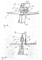
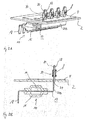
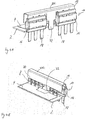
- the devices illustrated in the figures form combined circuit-based power distribution and power protection systems. They serve, for example, for use in a motor vehicle and are connected when installed with a particular coming from the car battery power supply line. On the output side, several output lines are connected to the devices in the installed state in order to supply individual subcircuits in the motor vehicle with power.
- the power supply line is connected directly or indirectly, for example via a screw or other contact with the feed plate 4, not shown here.
- the devices each comprise a printed circuit board 2 shown only in a greatly simplified manner, on which a feed line formed as a feed plate 4 is arranged.
- the feed plate 4 is located over a large area on the top of the circuit board 4 and is connected to this particular electrically to the power supply.
- the feed plate 4 is connected to a multiple fuse 10.
- This comprises a bent punching plate 12, in the central securing area by means of a corresponding configuration of the punching webs a plurality of fuses 14 are formed.
- the stamped sheet is surrounded by one or more fuse housings 16.
- the stamped sheet 12 has a plurality of output contact tongues 18 which form output contacts. These are each hedged via a fuse 14.
- the stamped sheet 12 also has a plurality of input contact tongues 20, with which the stamped grid 12 is inserted into the plug-in contact elements 8.
- the stamped grid 12 is preferably made of copper, a copper alloy or zinc with a surface coating based on silver or tin.
- the output contact tongues 18 are arranged on the opposite to the feed plate 4.
- the power connection from the feed plate 4 to the output contact tabs 18 is therefore routed from one circuit board side to the other circuit board side.
- On the printed circuit board 2 itself usually electrical or electronic functions are integrated in a manner not shown here, and the circuit board 2 is equipped with corresponding electrical or electronic components and has integrated conductor tracks.
- the power supply of the circuit board 2 takes place here via the feed plate 4, that is, the feed plate 4 is used both for feeding Power in the circuit board 2 as well as the power distribution to the individual output contact tongues 18 of the multiple fuse 10th
- the plug-in contact elements 8 are formed by solder contacts, which are soldered onto the printed circuit board 2.
- the plug-in contact elements 8 are inserted into the printed circuit board 2.
- a bent tab 22 of the feed plate 14 is inserted into the circuit board 2 and soldered directly to the inserted foot of the plug contact element 8 in this area.
- the plug contact elements 8 are in this case oriented perpendicular to the printed circuit board 2, so that the input contact tongues 20 from above, ie perpendicular to the circuit board 2, are inserted.
- the plug contact elements 8 in this case have contact springs in the upper plug-in region.
- the punched grid 12 having the output contact tongues 18 is bent in a U-shape above the printed circuit board 2 and thereby forms a U-shaped connecting element 23A.
- the securing area is provided above the printed circuit board 2 on the same side of the feed plate 4.
- the fuse housing 16 extends here due to the U-shaped configuration of the stamped grid 12 parallel to the plug contact elements 8 also perpendicular to the circuit board 2.
- the lead frame 12 is passed through an opening 24 in the circuit board 2, so that the output contact tongues 18 on the other Side of the printed circuit board 2 are located.
- an output housing 26 is shown, in which the individual output contact tongues 18 open.
- the output housing 26 is used for direct contacting of the output contact tabs 18.
- the output contact housing 26 forms a kind of plug with internal integrated plug-in contact elements, with which the respective output lines are connected. For contacting the output line then only needs the plug housing forming the output housing 26 to be plugged onto the respective output contact tabs 18. In this case, different output housing 26 or plug are typically provided for different circuits.
- the plug contact elements 18 are in turn soldered to the printed circuit board 2.
- the feed plate 4 is guided around the individual plug-in contact elements 8.
- the individual tabs 22 are not contacted in this embodiment directly with the individual plug contact elements. Rather, the contacting takes place via conductor tracks, not shown here, or conductive areas on the printed circuit board 2. Alternatively, the conductive connection is made from the tabs 22 to the plug contact elements 8 via the solder joint, not shown here.
- the lead frame 12 is stepped or S-shaped and the input contact tongues 20 are guided from below through a plurality of apertures 24 through the circuit board 2 and plugged into the individual plug contact elements 8.
- the step-like configuration of the stamped grid 12 forms a region extending below the printed circuit board 2 and parallel thereto, in which the securing region with the fuse housing 16 is provided.
- the fuse housing 16 is therefore oriented in this embodiment opposite to the feed plate 4 and parallel to the circuit board 2, and connected to an approximately L-shaped connecting element 23 B with the plug contact elements 8.
- the feed plate 4 has a plurality of bent contact lugs 28, which are provided for contacting with the input contact tongues 20.
- a contact over spring 30 is pushed over the tongues 20 and tabs 28, so that the two parts 28, 20 are pressed against one another in a contacting manner with their flat sides. In this embodiment, therefore, no soldering in the plug contact elements 8 required.
- the contact tabs 28 are bent in a simple manner from the center of the feed plate 4.
- an additional feed-in contact tongue 32 is provided as an essential difference from the preceding embodiments, to which the power supply line is to be connected.
- the feed-in contact tongue 32 is in this case arranged on the same side as the output contact tongues 18 and is a section of the stamped grid 12. Since the power supply takes place via the feed-in contact tongue 32, this has a greater width than the other output contact tongues 18.
- the EinspeiseWalletzunge 32 is arranged centrally and on both sides of a plurality of output contact tongues 18 and a respective fuse housing 16 are provided.
- the punched grid 12 is again bent in a U-shape, so that the plug-in contact elements 18 and the fuse housing 16 are aligned above the circuit board 2 perpendicular to this.
- the plug contact elements 8 are in turn formed as solder contacts.
- the lead frame 12 therefore has a multiple function.
- the protection of the outgoing output lines in the sense of multiple backup ensures the power distribution both to the output lines on the Ninontaktzept 18 and other high-current consumers, ensures the power supply of the circuit board 2 with the consumers arranged thereon and also allows by a simple plug-in contact via the feed-in contact tongue 32 the connection to a supply cable, such as a battery cable.
- a screw 34 is provided.
- the feed plate 4 is bent upward end and forms a step with an upper contact surface.
- a corresponding contact surface of the stamped grid 12 is clamped by means of a screw 36.
- the punched grid 12 is also bent in the manner of an L's, so that the fuse housing 16 is oriented perpendicular to the printed circuit board 2.
- the screw 36 is supported in a support body 38 made of insulating material, in particular plastic, whereby a high mechanical stability is achieved.
Landscapes
- Fuses (AREA)
- Details Of Connecting Devices For Male And Female Coupling (AREA)
- Connections Arranged To Contact A Plurality Of Conductors (AREA)
- Electrical Discharge Machining, Electrochemical Machining, And Combined Machining (AREA)
- Control Of El Displays (AREA)
- Coupling Device And Connection With Printed Circuit (AREA)
Applications Claiming Priority (1)
| Application Number | Priority Date | Filing Date | Title |
|---|---|---|---|
| DE102006010071A DE102006010071B3 (de) | 2006-03-04 | 2006-03-04 | Vorrichtung zur Stromverteilung |
Publications (3)
| Publication Number | Publication Date |
|---|---|
| EP1830376A2 true EP1830376A2 (fr) | 2007-09-05 |
| EP1830376A3 EP1830376A3 (fr) | 2009-03-25 |
| EP1830376B1 EP1830376B1 (fr) | 2011-05-18 |
Family
ID=38009502
Family Applications (1)
| Application Number | Title | Priority Date | Filing Date |
|---|---|---|---|
| EP20070004203 Not-in-force EP1830376B1 (fr) | 2006-03-04 | 2007-03-01 | Dispositif destiné à la distribution de courant |
Country Status (6)
| Country | Link |
|---|---|
| US (1) | US7515399B2 (fr) |
| EP (1) | EP1830376B1 (fr) |
| AT (1) | ATE510294T1 (fr) |
| DE (1) | DE102006010071B3 (fr) |
| ES (1) | ES2366134T3 (fr) |
| PT (1) | PT1830376E (fr) |
Families Citing this family (8)
| Publication number | Priority date | Publication date | Assignee | Title |
|---|---|---|---|---|
| DE102008049101A1 (de) | 2008-09-26 | 2009-05-07 | Daimler Ag | Vorrichtung zur Stromverteilung |
| US20100141375A1 (en) * | 2008-12-09 | 2010-06-10 | Square D Company | Trace fuse with positive expulsion |
| DE102013002706B4 (de) | 2013-02-16 | 2025-01-30 | Volkswagen Aktiengesellschaft | Verbindungselement zum Verbinden von Kontakten einer Sensoreinheit eines Lenkhilfesystems mit einer elektrischen Steuereinheit sowie Lenkhilfesystem mit Verbindungselement |
| US10136522B2 (en) * | 2015-05-11 | 2018-11-20 | Lear Corporation | Electrical terminal and circuit board assembly containing the same |
| US9997851B1 (en) * | 2017-04-21 | 2018-06-12 | Hewlett Packard Enterprise Development Lp | Power connectors with fusible regions |
| WO2019182598A1 (fr) | 2018-03-22 | 2019-09-26 | Hewlett-Packard Development Company, L.P. | Fusibles électroniques à commutateur unique ayant de multiples puissance de sortie |
| DE102020203560A1 (de) * | 2020-03-19 | 2021-09-23 | Ellenberger & Poensgen Gmbh | Stromverteiler eines Bordnetzes eines Kraftfahrzeugs |
| AU2024368730A1 (en) * | 2023-10-23 | 2026-04-16 | Relectrify Holdings Pty Ltd | Fusible connection tab |
Citations (1)
| Publication number | Priority date | Publication date | Assignee | Title |
|---|---|---|---|---|
| JP2000030600A (ja) | 1998-07-10 | 2000-01-28 | Taiheiyo Seiko Kk | 多極形ヒューズ素子 |
Family Cites Families (22)
| Publication number | Priority date | Publication date | Assignee | Title |
|---|---|---|---|---|
| DE3022115C2 (de) * | 1980-06-12 | 1985-10-10 | Bayerische Motoren Werke AG, 8000 München | Sicherungs- und Verteilerkasten für Kraftfahrzeuge |
| US4687270A (en) * | 1986-07-18 | 1987-08-18 | General Motors Corporation | Fuse package |
| US4806118A (en) * | 1988-01-19 | 1989-02-21 | General Motors Corporation | Fuse package |
| US4846733A (en) * | 1988-08-19 | 1989-07-11 | Lucas Electrical Electronic Systems Limited | Accessory fuse block |
| US5112242A (en) * | 1990-11-20 | 1992-05-12 | Foxconn International, Inc. | Durable latch for memory module board |
| US5346411A (en) * | 1993-12-13 | 1994-09-13 | Nikkinen Kurt D | Tap-in blade fuse |
| JPH087743A (ja) * | 1994-06-15 | 1996-01-12 | Yazaki Corp | ヒュージブルリンク及びその組立方法 |
| EP0760313A3 (fr) * | 1995-08-25 | 1998-11-11 | Mannesmann VDO AG | Centrale électrique pour véhicules |
| US5795193A (en) * | 1996-10-23 | 1998-08-18 | Yazaki Corporation | Power distribution box with busbar having bolt retaining means |
| JP3198966B2 (ja) * | 1997-03-13 | 2001-08-13 | 住友電装株式会社 | 電気接続箱 |
| US5831814A (en) * | 1997-03-14 | 1998-11-03 | General Motors Corporation | Electrical center bus plate assembly |
| FR2761204B1 (fr) * | 1997-03-24 | 1999-05-14 | Siemens Automotive Sa | Dispositif de distribution d'energie electrique dans plusieurs circuits alimentes en paralleles, et procede de fabrication de ce dispositif |
| US6280253B1 (en) * | 1999-04-22 | 2001-08-28 | Visteon Global Technologies, Inc. | Method and apparatus for selectively connecting electrical circuits and components |
| US6815841B1 (en) * | 1999-11-03 | 2004-11-09 | Littelfuse, Inc. | Fuse arrangements and fuse boxes for a vehicle |
| US6322376B1 (en) * | 2000-03-31 | 2001-11-27 | Yazaki North America | Stud bolt holder for a power distribution box |
| US6716065B1 (en) * | 2000-06-01 | 2004-04-06 | Leftek International, Llc | Electrical systems with paired bus connectors |
| JP2002329453A (ja) * | 2001-04-27 | 2002-11-15 | Yazaki Corp | 連鎖型ヒューズ組立体およびそのレイアウト方法 |
| JP2002329458A (ja) * | 2001-05-02 | 2002-11-15 | Taiheiyo Seiko Kk | 車両用多極形ヒューズ素子 |
| JP2003218554A (ja) * | 2001-11-14 | 2003-07-31 | Yazaki Corp | 電源分配箱及びパワーデバイスモジュール |
| US6878004B2 (en) * | 2002-03-04 | 2005-04-12 | Littelfuse, Inc. | Multi-element fuse array |
| DE10247307B3 (de) * | 2002-10-10 | 2004-01-22 | Siemens Ag | Fahrzeugbordnetz |
| DE10249575B3 (de) * | 2002-10-24 | 2004-02-19 | Leopold Kostal Gmbh & Co Kg | Elektrische Einrichtung |
-
2006
- 2006-03-04 DE DE102006010071A patent/DE102006010071B3/de not_active Expired - Fee Related
-
2007
- 2007-03-01 AT AT07004203T patent/ATE510294T1/de active
- 2007-03-01 PT PT07004203T patent/PT1830376E/pt unknown
- 2007-03-01 ES ES07004203T patent/ES2366134T3/es active Active
- 2007-03-01 EP EP20070004203 patent/EP1830376B1/fr not_active Not-in-force
- 2007-03-02 US US11/713,819 patent/US7515399B2/en not_active Expired - Fee Related
Patent Citations (1)
| Publication number | Priority date | Publication date | Assignee | Title |
|---|---|---|---|---|
| JP2000030600A (ja) | 1998-07-10 | 2000-01-28 | Taiheiyo Seiko Kk | 多極形ヒューズ素子 |
Also Published As
| Publication number | Publication date |
|---|---|
| EP1830376B1 (fr) | 2011-05-18 |
| PT1830376E (pt) | 2011-08-23 |
| DE102006010071B3 (de) | 2007-09-27 |
| ES2366134T3 (es) | 2011-10-17 |
| US7515399B2 (en) | 2009-04-07 |
| ATE510294T1 (de) | 2011-06-15 |
| EP1830376A3 (fr) | 2009-03-25 |
| US20070263344A1 (en) | 2007-11-15 |
Similar Documents
| Publication | Publication Date | Title |
|---|---|---|
| DE69404840T2 (de) | Hybridzentralelektrik | |
| DE102007036646B4 (de) | Sicherungseinsatzeinheit | |
| EP1830376B1 (fr) | Dispositif destiné à la distribution de courant | |
| DE19938068C2 (de) | Leistungsverteilungszentrum | |
| DE69908896T2 (de) | Elektrische Anschlussdose mit einer Sammelschiene | |
| DE4323827C1 (de) | Steckbare Baugruppe | |
| DE10232650B4 (de) | Elektrischer Verbindungskasten und Verfahren zur Herstellung desselben | |
| EP0394327B1 (fr) | Centrale electrique pour vehicules a moteur | |
| EP2790272B1 (fr) | Installation de répartition de courant ainsi que sa mise en contact et la protection des lignes qui en sortent | |
| DE102014210044A1 (de) | Stromverteilungskasten | |
| EP2608323B1 (fr) | Liaison pour passage de boîtier | |
| EP3852201A1 (fr) | Système de connexion directe pour la connexion d'un connecteur à une carte de circuit imprimé | |
| DE102013111571A1 (de) | Gerätegehäuse, Elektronikgeräte und Steckkontaktträger | |
| EP1168550A2 (fr) | Distributeur de courant | |
| DE10247307B3 (de) | Fahrzeugbordnetz | |
| DE102006024391A1 (de) | Sicherungseinheit | |
| EP1700516A1 (fr) | Ensemble comprenant un element de contact | |
| DE102008049101A1 (de) | Vorrichtung zur Stromverteilung | |
| DE202011102353U1 (de) | Sicherungsanordnung insbesondere für ein Kraftfahrzeug-Bordnetz | |
| EP2324536A1 (fr) | Contact enfichable de puissance et agencement de carte de circuits | |
| DE69411294T2 (de) | Anschlussblock für elektrisches Geräte und Leistungsumformer mit einem derartigen Anschlu block | |
| DE102007003652B4 (de) | Elektrische Überbrückung | |
| DE20214126U1 (de) | Elektrische Schaltungsanordnung | |
| DE102015111885A1 (de) | Sicherung für Stromverteiler | |
| DE19749119C2 (de) | Elektrisches Verbindungssystem |
Legal Events
| Date | Code | Title | Description |
|---|---|---|---|
| PUAI | Public reference made under article 153(3) epc to a published international application that has entered the european phase |
Free format text: ORIGINAL CODE: 0009012 |
|
| AK | Designated contracting states |
Kind code of ref document: A2 Designated state(s): AT BE BG CH CY CZ DE DK EE ES FI FR GB GR HU IE IS IT LI LT LU LV MC MT NL PL PT RO SE SI SK TR |
|
| AX | Request for extension of the european patent |
Extension state: AL BA HR MK YU |
|
| PUAL | Search report despatched |
Free format text: ORIGINAL CODE: 0009013 |
|
| AK | Designated contracting states |
Kind code of ref document: A3 Designated state(s): AT BE BG CH CY CZ DE DK EE ES FI FR GB GR HU IE IS IT LI LT LU LV MC MT NL PL PT RO SE SI SK TR |
|
| AX | Request for extension of the european patent |
Extension state: AL BA HR MK RS |
|
| 17P | Request for examination filed |
Effective date: 20090922 |
|
| AKX | Designation fees paid |
Designated state(s): AT BE BG CH CY CZ DE DK EE ES FI FR GB GR HU IE IS IT LI LT LU LV MC MT NL PL PT RO SE SI SK TR |
|
| 17Q | First examination report despatched |
Effective date: 20101129 |
|
| GRAP | Despatch of communication of intention to grant a patent |
Free format text: ORIGINAL CODE: EPIDOSNIGR1 |
|
| GRAS | Grant fee paid |
Free format text: ORIGINAL CODE: EPIDOSNIGR3 |
|
| GRAA | (expected) grant |
Free format text: ORIGINAL CODE: 0009210 |
|
| REG | Reference to a national code |
Ref country code: GB Ref legal event code: FG4D Free format text: NOT ENGLISH |
|
| REG | Reference to a national code |
Ref country code: CH Ref legal event code: EP |
|
| REG | Reference to a national code |
Ref country code: IE Ref legal event code: FG4D Free format text: LANGUAGE OF EP DOCUMENT: GERMAN |
|
| REG | Reference to a national code |
Ref country code: DE Ref legal event code: R096 Ref document number: 502007007210 Country of ref document: DE Effective date: 20110630 |
|
| REG | Reference to a national code |
Ref country code: PT Ref legal event code: SC4A Free format text: AVAILABILITY OF NATIONAL TRANSLATION Effective date: 20110805 |
|
| REG | Reference to a national code |
Ref country code: NL Ref legal event code: VDEP Effective date: 20110518 |
|
| REG | Reference to a national code |
Ref country code: SE Ref legal event code: TRGR |
|
| REG | Reference to a national code |
Ref country code: ES Ref legal event code: FG2A Ref document number: 2366134 Country of ref document: ES Kind code of ref document: T3 Effective date: 20111017 |
|
| PG25 | Lapsed in a contracting state [announced via postgrant information from national office to epo] |
Ref country code: LT Free format text: LAPSE BECAUSE OF FAILURE TO SUBMIT A TRANSLATION OF THE DESCRIPTION OR TO PAY THE FEE WITHIN THE PRESCRIBED TIME-LIMIT Effective date: 20110518 |
|
| PG25 | Lapsed in a contracting state [announced via postgrant information from national office to epo] |
Ref country code: LV Free format text: LAPSE BECAUSE OF FAILURE TO SUBMIT A TRANSLATION OF THE DESCRIPTION OR TO PAY THE FEE WITHIN THE PRESCRIBED TIME-LIMIT Effective date: 20110518 Ref country code: IS Free format text: LAPSE BECAUSE OF FAILURE TO SUBMIT A TRANSLATION OF THE DESCRIPTION OR TO PAY THE FEE WITHIN THE PRESCRIBED TIME-LIMIT Effective date: 20110918 Ref country code: CY Free format text: LAPSE BECAUSE OF FAILURE TO SUBMIT A TRANSLATION OF THE DESCRIPTION OR TO PAY THE FEE WITHIN THE PRESCRIBED TIME-LIMIT Effective date: 20110518 Ref country code: FI Free format text: LAPSE BECAUSE OF FAILURE TO SUBMIT A TRANSLATION OF THE DESCRIPTION OR TO PAY THE FEE WITHIN THE PRESCRIBED TIME-LIMIT Effective date: 20110518 Ref country code: SI Free format text: LAPSE BECAUSE OF FAILURE TO SUBMIT A TRANSLATION OF THE DESCRIPTION OR TO PAY THE FEE WITHIN THE PRESCRIBED TIME-LIMIT Effective date: 20110518 Ref country code: GR Free format text: LAPSE BECAUSE OF FAILURE TO SUBMIT A TRANSLATION OF THE DESCRIPTION OR TO PAY THE FEE WITHIN THE PRESCRIBED TIME-LIMIT Effective date: 20110819 |
|
| REG | Reference to a national code |
Ref country code: IE Ref legal event code: FD4D |
|
| PG25 | Lapsed in a contracting state [announced via postgrant information from national office to epo] |
Ref country code: NL Free format text: LAPSE BECAUSE OF FAILURE TO SUBMIT A TRANSLATION OF THE DESCRIPTION OR TO PAY THE FEE WITHIN THE PRESCRIBED TIME-LIMIT Effective date: 20110518 |
|
| PG25 | Lapsed in a contracting state [announced via postgrant information from national office to epo] |
Ref country code: CZ Free format text: LAPSE BECAUSE OF FAILURE TO SUBMIT A TRANSLATION OF THE DESCRIPTION OR TO PAY THE FEE WITHIN THE PRESCRIBED TIME-LIMIT Effective date: 20110518 Ref country code: IE Free format text: LAPSE BECAUSE OF FAILURE TO SUBMIT A TRANSLATION OF THE DESCRIPTION OR TO PAY THE FEE WITHIN THE PRESCRIBED TIME-LIMIT Effective date: 20110518 Ref country code: EE Free format text: LAPSE BECAUSE OF FAILURE TO SUBMIT A TRANSLATION OF THE DESCRIPTION OR TO PAY THE FEE WITHIN THE PRESCRIBED TIME-LIMIT Effective date: 20110518 |
|
| PG25 | Lapsed in a contracting state [announced via postgrant information from national office to epo] |
Ref country code: RO Free format text: LAPSE BECAUSE OF FAILURE TO SUBMIT A TRANSLATION OF THE DESCRIPTION OR TO PAY THE FEE WITHIN THE PRESCRIBED TIME-LIMIT Effective date: 20110518 Ref country code: SK Free format text: LAPSE BECAUSE OF FAILURE TO SUBMIT A TRANSLATION OF THE DESCRIPTION OR TO PAY THE FEE WITHIN THE PRESCRIBED TIME-LIMIT Effective date: 20110518 Ref country code: DK Free format text: LAPSE BECAUSE OF FAILURE TO SUBMIT A TRANSLATION OF THE DESCRIPTION OR TO PAY THE FEE WITHIN THE PRESCRIBED TIME-LIMIT Effective date: 20110518 Ref country code: PL Free format text: LAPSE BECAUSE OF FAILURE TO SUBMIT A TRANSLATION OF THE DESCRIPTION OR TO PAY THE FEE WITHIN THE PRESCRIBED TIME-LIMIT Effective date: 20110518 |
|
| PLBE | No opposition filed within time limit |
Free format text: ORIGINAL CODE: 0009261 |
|
| STAA | Information on the status of an ep patent application or granted ep patent |
Free format text: STATUS: NO OPPOSITION FILED WITHIN TIME LIMIT |
|
| 26N | No opposition filed |
Effective date: 20120221 |
|
| REG | Reference to a national code |
Ref country code: DE Ref legal event code: R097 Ref document number: 502007007210 Country of ref document: DE Effective date: 20120221 |
|
| PGFP | Annual fee paid to national office [announced via postgrant information from national office to epo] |
Ref country code: IT Payment date: 20120324 Year of fee payment: 6 |
|
| BERE | Be: lapsed |
Owner name: LEONI BORDNETZ-SYSTEME G.M.B.H. Effective date: 20120331 |
|
| PG25 | Lapsed in a contracting state [announced via postgrant information from national office to epo] |
Ref country code: MC Free format text: LAPSE BECAUSE OF NON-PAYMENT OF DUE FEES Effective date: 20120331 |
|
| REG | Reference to a national code |
Ref country code: CH Ref legal event code: PL |
|
| PG25 | Lapsed in a contracting state [announced via postgrant information from national office to epo] |
Ref country code: CH Free format text: LAPSE BECAUSE OF NON-PAYMENT OF DUE FEES Effective date: 20120331 Ref country code: BE Free format text: LAPSE BECAUSE OF NON-PAYMENT OF DUE FEES Effective date: 20120331 Ref country code: LI Free format text: LAPSE BECAUSE OF NON-PAYMENT OF DUE FEES Effective date: 20120331 |
|
| PGFP | Annual fee paid to national office [announced via postgrant information from national office to epo] |
Ref country code: ES Payment date: 20130320 Year of fee payment: 7 Ref country code: SE Payment date: 20130319 Year of fee payment: 7 |
|
| REG | Reference to a national code |
Ref country code: AT Ref legal event code: MM01 Ref document number: 510294 Country of ref document: AT Kind code of ref document: T Effective date: 20120301 |
|
| PG25 | Lapsed in a contracting state [announced via postgrant information from national office to epo] |
Ref country code: BG Free format text: LAPSE BECAUSE OF FAILURE TO SUBMIT A TRANSLATION OF THE DESCRIPTION OR TO PAY THE FEE WITHIN THE PRESCRIBED TIME-LIMIT Effective date: 20110818 |
|
| PG25 | Lapsed in a contracting state [announced via postgrant information from national office to epo] |
Ref country code: AT Free format text: LAPSE BECAUSE OF NON-PAYMENT OF DUE FEES Effective date: 20120301 Ref country code: MT Free format text: LAPSE BECAUSE OF FAILURE TO SUBMIT A TRANSLATION OF THE DESCRIPTION OR TO PAY THE FEE WITHIN THE PRESCRIBED TIME-LIMIT Effective date: 20110518 |
|
| PG25 | Lapsed in a contracting state [announced via postgrant information from national office to epo] |
Ref country code: TR Free format text: LAPSE BECAUSE OF FAILURE TO SUBMIT A TRANSLATION OF THE DESCRIPTION OR TO PAY THE FEE WITHIN THE PRESCRIBED TIME-LIMIT Effective date: 20110518 |
|
| PG25 | Lapsed in a contracting state [announced via postgrant information from national office to epo] |
Ref country code: LU Free format text: LAPSE BECAUSE OF NON-PAYMENT OF DUE FEES Effective date: 20120301 |
|
| PGFP | Annual fee paid to national office [announced via postgrant information from national office to epo] |
Ref country code: PT Payment date: 20140218 Year of fee payment: 8 |
|
| PG25 | Lapsed in a contracting state [announced via postgrant information from national office to epo] |
Ref country code: HU Free format text: LAPSE BECAUSE OF FAILURE TO SUBMIT A TRANSLATION OF THE DESCRIPTION OR TO PAY THE FEE WITHIN THE PRESCRIBED TIME-LIMIT Effective date: 20070301 |
|
| REG | Reference to a national code |
Ref country code: SE Ref legal event code: EUG |
|
| PG25 | Lapsed in a contracting state [announced via postgrant information from national office to epo] |
Ref country code: SE Free format text: LAPSE BECAUSE OF NON-PAYMENT OF DUE FEES Effective date: 20140302 |
|
| PG25 | Lapsed in a contracting state [announced via postgrant information from national office to epo] |
Ref country code: IT Free format text: LAPSE BECAUSE OF NON-PAYMENT OF DUE FEES Effective date: 20140301 |
|
| REG | Reference to a national code |
Ref country code: PT Ref legal event code: MM4A Free format text: LAPSE DUE TO NON-PAYMENT OF FEES Effective date: 20150901 |
|
| PG25 | Lapsed in a contracting state [announced via postgrant information from national office to epo] |
Ref country code: PT Free format text: LAPSE BECAUSE OF NON-PAYMENT OF DUE FEES Effective date: 20150901 |
|
| REG | Reference to a national code |
Ref country code: FR Ref legal event code: PLFP Year of fee payment: 10 |
|
| PG25 | Lapsed in a contracting state [announced via postgrant information from national office to epo] |
Ref country code: ES Free format text: LAPSE BECAUSE OF NON-PAYMENT OF DUE FEES Effective date: 20140302 |
|
| REG | Reference to a national code |
Ref country code: FR Ref legal event code: PLFP Year of fee payment: 11 |
|
| REG | Reference to a national code |
Ref country code: FR Ref legal event code: PLFP Year of fee payment: 12 |
|
| PGFP | Annual fee paid to national office [announced via postgrant information from national office to epo] |
Ref country code: FR Payment date: 20210322 Year of fee payment: 15 |
|
| PGFP | Annual fee paid to national office [announced via postgrant information from national office to epo] |
Ref country code: DE Payment date: 20210323 Year of fee payment: 15 Ref country code: GB Payment date: 20210324 Year of fee payment: 15 |
|
| REG | Reference to a national code |
Ref country code: DE Ref legal event code: R081 Ref document number: 502007007210 Country of ref document: DE Owner name: LEONI BORDNETZ-SYSTEME GMBH, DE Free format text: FORMER OWNER: LEONI BORDNETZ-SYSTEME GMBH, 90402 NUERNBERG, DE |
|
| REG | Reference to a national code |
Ref country code: DE Ref legal event code: R119 Ref document number: 502007007210 Country of ref document: DE |
|
| GBPC | Gb: european patent ceased through non-payment of renewal fee |
Effective date: 20220301 |
|
| PG25 | Lapsed in a contracting state [announced via postgrant information from national office to epo] |
Ref country code: GB Free format text: LAPSE BECAUSE OF NON-PAYMENT OF DUE FEES Effective date: 20220301 Ref country code: FR Free format text: LAPSE BECAUSE OF NON-PAYMENT OF DUE FEES Effective date: 20220331 Ref country code: DE Free format text: LAPSE BECAUSE OF NON-PAYMENT OF DUE FEES Effective date: 20221001 |