EP1830558B1 - Système de commande à distance, commande à distance et serveur de commande à distance - Google Patents
Système de commande à distance, commande à distance et serveur de commande à distance Download PDFInfo
- Publication number
- EP1830558B1 EP1830558B1 EP05814133.4A EP05814133A EP1830558B1 EP 1830558 B1 EP1830558 B1 EP 1830558B1 EP 05814133 A EP05814133 A EP 05814133A EP 1830558 B1 EP1830558 B1 EP 1830558B1
- Authority
- EP
- European Patent Office
- Prior art keywords
- controlled
- remote
- request
- remote commander
- network
- Prior art date
- Legal status (The legal status is an assumption and is not a legal conclusion. Google has not performed a legal analysis and makes no representation as to the accuracy of the status listed.)
- Ceased
Links
Images












Classifications
-
- H—ELECTRICITY
- H04—ELECTRIC COMMUNICATION TECHNIQUE
- H04Q—SELECTING
- H04Q9/00—Arrangements in telecontrol or telemetry systems for selectively calling a substation from a main station, in which substation desired apparatus is selected for applying a control signal thereto or for obtaining measured values therefrom
- H04Q9/02—Automatically-operated arrangements
-
- H—ELECTRICITY
- H04—ELECTRIC COMMUNICATION TECHNIQUE
- H04N—PICTORIAL COMMUNICATION, e.g. TELEVISION
- H04N21/00—Selective content distribution, e.g. interactive television or video on demand [VOD]
- H04N21/40—Client devices specifically adapted for the reception of or interaction with content, e.g. set-top-box [STB]; Operations thereof
- H04N21/41—Structure of client; Structure of client peripherals
- H04N21/422—Input-only peripherals, i.e. input devices connected to specially adapted client devices, e.g. global positioning system [GPS]
- H04N21/42204—User interfaces specially adapted for controlling a client device through a remote control device; Remote control devices therefor
- H04N21/42206—User interfaces specially adapted for controlling a client device through a remote control device; Remote control devices therefor characterized by hardware details
- H04N21/42208—Display device provided on the remote control
- H04N21/42209—Display device provided on the remote control for displaying non-command information, e.g. electronic programme guide [EPG], e-mail, messages or a second television channel
-
- G—PHYSICS
- G08—SIGNALLING
- G08C—TRANSMISSION SYSTEMS FOR MEASURED VALUES, CONTROL OR SIMILAR SIGNALS
- G08C23/00—Non-electrical signal transmission systems, e.g. optical systems
- G08C23/04—Non-electrical signal transmission systems, e.g. optical systems using light waves, e.g. infrared
-
- H—ELECTRICITY
- H04—ELECTRIC COMMUNICATION TECHNIQUE
- H04B—TRANSMISSION
- H04B1/00—Details of transmission systems, not covered by a single one of groups H04B3/00 - H04B13/00; Details of transmission systems not characterised by the medium used for transmission
- H04B1/06—Receivers
- H04B1/16—Circuits
- H04B1/20—Circuits for coupling gramophone pick-up, recorder output, or microphone to receiver
- H04B1/205—Circuits for coupling gramophone pick-up, recorder output, or microphone to receiver with control bus for exchanging commands between units
-
- H—ELECTRICITY
- H04—ELECTRIC COMMUNICATION TECHNIQUE
- H04N—PICTORIAL COMMUNICATION, e.g. TELEVISION
- H04N21/00—Selective content distribution, e.g. interactive television or video on demand [VOD]
- H04N21/40—Client devices specifically adapted for the reception of or interaction with content, e.g. set-top-box [STB]; Operations thereof
- H04N21/41—Structure of client; Structure of client peripherals
- H04N21/422—Input-only peripherals, i.e. input devices connected to specially adapted client devices, e.g. global positioning system [GPS]
- H04N21/42204—User interfaces specially adapted for controlling a client device through a remote control device; Remote control devices therefor
-
- H—ELECTRICITY
- H04—ELECTRIC COMMUNICATION TECHNIQUE
- H04N—PICTORIAL COMMUNICATION, e.g. TELEVISION
- H04N21/00—Selective content distribution, e.g. interactive television or video on demand [VOD]
- H04N21/40—Client devices specifically adapted for the reception of or interaction with content, e.g. set-top-box [STB]; Operations thereof
- H04N21/41—Structure of client; Structure of client peripherals
- H04N21/422—Input-only peripherals, i.e. input devices connected to specially adapted client devices, e.g. global positioning system [GPS]
- H04N21/4227—Providing Remote input by a user located remotely from the client device, e.g. at work
-
- H—ELECTRICITY
- H04—ELECTRIC COMMUNICATION TECHNIQUE
- H04N—PICTORIAL COMMUNICATION, e.g. TELEVISION
- H04N21/00—Selective content distribution, e.g. interactive television or video on demand [VOD]
- H04N21/40—Client devices specifically adapted for the reception of or interaction with content, e.g. set-top-box [STB]; Operations thereof
- H04N21/43—Processing of content or additional data, e.g. demultiplexing additional data from a digital video stream; Elementary client operations, e.g. monitoring of home network or synchronising decoder's clock; Client middleware
- H04N21/431—Generation of visual interfaces for content selection or interaction; Content or additional data rendering
- H04N21/4312—Generation of visual interfaces for content selection or interaction; Content or additional data rendering involving specific graphical features, e.g. screen layout, special fonts or colors, blinking icons, highlights or animations
- H04N21/4316—Generation of visual interfaces for content selection or interaction; Content or additional data rendering involving specific graphical features, e.g. screen layout, special fonts or colors, blinking icons, highlights or animations for displaying supplemental content in a region of the screen, e.g. an advertisement in a separate window
-
- H—ELECTRICITY
- H04—ELECTRIC COMMUNICATION TECHNIQUE
- H04N—PICTORIAL COMMUNICATION, e.g. TELEVISION
- H04N21/00—Selective content distribution, e.g. interactive television or video on demand [VOD]
- H04N21/40—Client devices specifically adapted for the reception of or interaction with content, e.g. set-top-box [STB]; Operations thereof
- H04N21/43—Processing of content or additional data, e.g. demultiplexing additional data from a digital video stream; Elementary client operations, e.g. monitoring of home network or synchronising decoder's clock; Client middleware
- H04N21/436—Interfacing a local distribution network, e.g. communicating with another STB or one or more peripheral devices inside the home
- H04N21/43615—Interfacing a Home Network, e.g. for connecting the client to a plurality of peripherals
-
- H—ELECTRICITY
- H04—ELECTRIC COMMUNICATION TECHNIQUE
- H04N—PICTORIAL COMMUNICATION, e.g. TELEVISION
- H04N21/00—Selective content distribution, e.g. interactive television or video on demand [VOD]
- H04N21/40—Client devices specifically adapted for the reception of or interaction with content, e.g. set-top-box [STB]; Operations thereof
- H04N21/47—End-user applications
- H04N21/482—End-user interface for programme selection
-
- H—ELECTRICITY
- H04—ELECTRIC COMMUNICATION TECHNIQUE
- H04N—PICTORIAL COMMUNICATION, e.g. TELEVISION
- H04N21/00—Selective content distribution, e.g. interactive television or video on demand [VOD]
- H04N21/60—Network structure or processes for video distribution between server and client or between remote clients; Control signalling between clients, server and network components; Transmission of management data between server and client, e.g. sending from server to client commands for recording incoming content stream; Communication details between server and client
- H04N21/63—Control signaling related to video distribution between client, server and network components; Network processes for video distribution between server and clients or between remote clients, e.g. transmitting basic layer and enhancement layers over different transmission paths, setting up a peer-to-peer communication via Internet between remote STB's; Communication protocols; Addressing
- H04N21/643—Communication protocols
- H04N21/64322—IP
-
- H—ELECTRICITY
- H04—ELECTRIC COMMUNICATION TECHNIQUE
- H04N—PICTORIAL COMMUNICATION, e.g. TELEVISION
- H04N21/00—Selective content distribution, e.g. interactive television or video on demand [VOD]
- H04N21/60—Network structure or processes for video distribution between server and client or between remote clients; Control signalling between clients, server and network components; Transmission of management data between server and client, e.g. sending from server to client commands for recording incoming content stream; Communication details between server and client
- H04N21/65—Transmission of management data between client and server
- H04N21/658—Transmission by the client directed to the server
- H04N21/6587—Control parameters, e.g. trick play commands, viewpoint selection
-
- H—ELECTRICITY
- H04—ELECTRIC COMMUNICATION TECHNIQUE
- H04N—PICTORIAL COMMUNICATION, e.g. TELEVISION
- H04N7/00—Television systems
- H04N7/16—Analogue secrecy systems; Analogue subscription systems
- H04N7/162—Authorising the user terminal, e.g. by paying; Registering the use of a subscription channel, e.g. billing
- H04N7/163—Authorising the user terminal, e.g. by paying; Registering the use of a subscription channel, e.g. billing by receiver means only
-
- H—ELECTRICITY
- H04—ELECTRIC COMMUNICATION TECHNIQUE
- H04W—WIRELESS COMMUNICATION NETWORKS
- H04W8/00—Network data management
- H04W8/22—Processing or transfer of terminal data, e.g. status or physical capabilities
- H04W8/24—Transfer of terminal data
-
- G—PHYSICS
- G08—SIGNALLING
- G08C—TRANSMISSION SYSTEMS FOR MEASURED VALUES, CONTROL OR SIMILAR SIGNALS
- G08C2201/00—Transmission systems of control signals via wireless link
- G08C2201/50—Receiving or transmitting feedback, e.g. replies, status updates, acknowledgements, from the controlled devices
-
- H—ELECTRICITY
- H04—ELECTRIC COMMUNICATION TECHNIQUE
- H04L—TRANSMISSION OF DIGITAL INFORMATION, e.g. TELEGRAPHIC COMMUNICATION
- H04L12/00—Data switching networks
- H04L12/28—Data switching networks characterised by path configuration, e.g. LAN [Local Area Networks] or WAN [Wide Area Networks]
- H04L12/2803—Home automation networks
- H04L12/2816—Controlling appliance services of a home automation network by calling their functionalities
- H04L12/282—Controlling appliance services of a home automation network by calling their functionalities based on user interaction within the home
-
- H—ELECTRICITY
- H04—ELECTRIC COMMUNICATION TECHNIQUE
- H04L—TRANSMISSION OF DIGITAL INFORMATION, e.g. TELEGRAPHIC COMMUNICATION
- H04L12/00—Data switching networks
- H04L12/28—Data switching networks characterised by path configuration, e.g. LAN [Local Area Networks] or WAN [Wide Area Networks]
- H04L12/2803—Home automation networks
- H04L2012/2847—Home automation networks characterised by the type of home appliance used
- H04L2012/2849—Audio/video appliances
Definitions
- the present invention relates to a remote control system, a remote commander, and a remote control server for remotely operating which a television receiver, a DVD player, and various other devices, such as an AV device, a CE device, and an information device, by using a remote commander, and more particularly, to a remote control system, a remote commander, and a remote control server for realizing remote control free from limitations on the directivity or available transmission distance from the remote commander to a device to be operated.
- the present invention relates to a remote control system, a remote commander, and a remote control server for providing two-way communication between the remote commander and a device to be operated using a network such as TCP/IP, and more particularly, to a remote control system, a remote commander, and a remote control server for remotely controlling a device in front of the user's eyes as a device to be operated from a plurality of devices without limitations on the directivity or available transmission distance.
- infrared remote controllers using an AM modulation method as means for inputting user operation commands to the devices in a remote manner have been developed and have already been established.
- Such a communication method using infrared light has advantages of low cost, low power consumption, substantially no legal restrictions in countries, and so forth. Elimination of hard-wired cabling also means that connectors for connecting cables are not necessary, leading to reduction in cost. There is no concern of mechanical exhaustion caused by inserting and removing connectors each time connection or disconnection occurs.
- the communication method using infrared light has a problem of directivity. Communication is not established unless a light-receiving unit of a receiver is set within the angle of view of a transmitter, which imposes a large limitation in use (see, for example, Patent Document 1). Further, the infrared communication method basically provides one-way communication, and has a problem that a transmission source is not able to receive a response from the other party and is not able to make a delivery confirmation.
- both devices that are to perform communication are provided with an infrared transmission function and an infrared reception function.
- infrared communication due to the problem of directivity, users of both devices are inconvenienced by having to direct their devices to the other devices to perform transmission operations.
- a communication device that relays an infrared operation signal for an electronic device, which is emitted from a remote commander, to operate an electronic device located at a place where an infrared operation signal from a dedicated remote controller does not directly reach has been proposed (see, for example, Patent Document 2).
- This communication device extracts a pulse waveform component by removing a carrier component from the infrared operation signal received from the remote commander, and transmits the pulse waveform component through a network.
- the communication device also modulates an infrared carrier by the pulse waveform component, and transmits the modulated infrared carrier to the electronic device to be operated.
- a remote operation system that is constructed with a simple device configuration in which no relay device or the like is used has been proposed (see, for example, Patent Document 3).
- a controller transmits capability information indicating the capability of input operations that can be performed by the controller to a device to be controlled, and the device to be controlled creates and returns remote-controller handling information for forming a user interface that can be realized within the range of the received capability information.
- the controller forms a user interface using the remote-controller handling information.
- a mobile-phone remote control system for allowing a reservation to be set in devices, such as home electric appliances, by using a mobile phone has been proposed (see, for example, Patent Document 4).
- a remote controller receives a signal from a mobile phone, and optically transmits a remote control signal for remotely controlling a device to be controlled according to the received signal.
- WO00/76130 describes a system in which devices in a home network can be controlled remotely, via a network connection.
- a user employing an Internet display device can communicate with a home access device which communicates, using a HAVi protocol/IEEE1394-bus network, with the devices in the home.
- WO00/04709 describes an interactive television program guide which can be accessed remotely by a user using a remote program guide access device (which can communicate with interactive television program guide equipment so as to display television listings).
- US 2003/195969 describes a system in which a remote commander uses infra-red signals to send commands to a set-top box.
- the set-top box is connected in a home digital network and can use the network connection to forward the user's command to another device in the network (including a device which can output infrared signals to control a further device).
- JP 2004-221779 describes a system in which a user operates a remote commander to send a command, via a network, to a signal output device.
- the signal output device converts the command into a control code and controls a further device using infrared signals corresponding to the control code.
- the present invention has been made in view of the abovementioned programs, and provides a remote control system comprising a remote commander and one or more devices to be controlled, in which said remote commander is used to operate said one or more devices to be controlled, wherein the remote commander and at least some of the devices to be controlled are provided with a network communication function, and a device to be controlled is adapted to be operated by means of a command through a network in response to a user input on the remote commander; wherein the remote commander is adapted to submit a request for device information relating to the devices to be controlled, through the network, and to display a device list concerning a device to be controlled including device information obtained in response to the request; characterized in that said remote commander and said at least some of the devices to be controlled are provided with a network communication function, the remote commander is configured to carry out two-way communication with said at least some of the devices on an IP network, and said device to be controlled is adapted to be operated by means of commands received on an IP network, the remote commander is adapted to submit via the IP
- system refers to a logical collection of a plurality of apparatuses (or function modules achieving a specific function) regardless of whether or not the apparatuses or function modules are housed in a single housing (the same applies to the following description).
- the device to be controlled returns a response through the network in response to a command transmitted by the remote commander through the network.
- the remote commander submits a request for data to the device to be controlled, and the device to be controlled returns the requested data through the network. Then, the remote commander decodes the data received from the device to be controlled to play back and output the data.
- the communication method using infrared light has advantages of low cost, low power consumption, substantially no legal restrictions in countries, and so forth.
- the communication method using infrared light has a problem of directivity. Communication is not established unless a light-receiving unit of a receiver is set within the angle of view of a transmitter, which imposes a large limitation in use.
- the infrared communication method basically provides one-way communication, and a transmission source is not able to receive a response from the other party and is not able to make a delivery confirmation.
- a communication medium with fewer limitations on the directivity or available communication range such as an IP network, is used to perform a remote control operation.
- a remote control system using an IP network two-way communication can be carried out between a remote controller and a device to be operated, and technical advantages of providing more reliable communication by means of a delivery confirmation (response), handling a GUI-based complex command scheme, and providing large-volume data transmission, such as moving-image streaming, using relatively broad bands are achieved.
- a television receiver to be operated by the remote controller distributes moving-image data subjected to reception processing, such as a child view, to an IP remote controller through an IP network so that the child view can be viewed on a display screen of the IP remote controller.
- the device to be controlled may convert the corresponding data content into a format that can be played back and output by the remote commander, and returns the converted data through the network.
- a request for video output of a desired television program or a request for AV output video from a device to be controlled such as an HDD recorder
- the video data is converted into a low-bit-rate data format that can be received and played back by an IP remote controller, such as MPEG4 data, and is distributed via streaming through a LAN.
- an IP remote controller such as MPEG4 data
- the process for conversion into a data format that can be played back and output by the remote commander according to the present invention is not limited to conversion of bit rates, such as conversion from a high bit rate to a low bit rate.
- Devices to be controlled may include an IR device that can be remotely controlled only by means of old infrared communication.
- a remote control server having a network communication function and a protocol conversion function of converting a command received through a network into an infrared command may be provided between the IP remote controller and the IR device.
- the remote control server Upon receiving an operation command for the IR device from the IP remote controller through an IP network, the remote control server converts the operation command into an infrared command, and transfers the infrared command to the IR device. Therefore, the IR device can be operated by the IP remote controller.
- the remote control server may extract from the IR device the data requested by the remote commander to the IR device, and may convert the extracted data into a format that can be played back and output by the remote commander to return the converted data to the remote commander through the network.
- the remote control server converts AV output video from a recording device serving as an IR device into a low-bit-rate data format that can be received and played back by the IP remote controller, such as MPEG4 data, and distributes the converted data via streaming through a LAN.
- the device to be controlled is a television receiver, it can extract EPG data from a received broadcast wave and can store the EPG data.
- the EPG data may be returned through the network in response to an EPG data request from the remote commander.
- the remote commander displays and outputs received EPG data.
- the remote commander may transmit a channel change request to a television receiver serving as a device to be controlled in response to designation of a channel on a current EPG data display view.
- the television receiver may convert video content received on the channel specified in the change request given by the remote commander into a format that can be played back and output by the remote commander, and may distribute the converted video content via streaming through the network. Then, the remote commander decodes the video content received, and displays video. The user can view a child view on the remote commander.
- the television receiver may change the display of the video to the channel specified in the change request given by the remote commander. This is an operation of throwing the video displayed on the remote commander onto a television screen.
- the remote commander may transmit a request for setting a reservation to record the program to a recording device serving as a device to be controlled.
- a recording reservation from the remote commander to the recording device may be set by the intervention of a remote control server.
- the remote control server Upon receiving a recording reservation request from the remote commander through the network, the remote control server converts the recording reservation request into infrared reservation data on the basis of EPG data, and transmits the recording reservation data via infrared light to an IR recording device that can be remotely controlled only by means of infrared communication. Then, the IR recording device sets a recording reservation according to the infrared reservation data from the remote control server.
- a recording device serving as a device to be controlled may convert the requested video content into a format that can be played back and output by the remote commander, and may distribute the converted video content via streaming through the network.
- the remote commander decodes the video content received, and displays video. The user can confirm the recorded video on the remote commander without changing the video displayed on the television set.
- Such an operation for recorded video on the remote commander may be performed by the intervention of a remote control server.
- the remote control server Upon receiving a video content request from the remote commander through the network, the remote control server converts the video content request into an infrared command, and transmits the video content request via infrared light to an IR recording device that can be remotely controlled only by means of infrared communication.
- the IR recording device outputs video content according to the infrared command from the remote control server.
- the remote control server converts the video content output from the IR recording device into a format that can be played back and output by the remote commander, and distributes the converted video content to the remote commander via streaming through the network.
- the remote commander can request a display device serving as a device to be controlled to change the display of the video to video content currently being displayed on the remote commander.
- the display device changes the screen from video received by a television set to video output from a recording device. This is an operation of throwing the video displayed on the remote commander onto a television screen.
- the remote commander is adapted to submit a request for device information to devices to be controlled having a network communication function through the network at the turn-on time or any other timing. Then, a device list concerning a device to be controlled that has responded with device information in response to the request is displayed. A device to be controlled that responded with device information in the past and that does not respond at present may be displayed in a grayed-out manner on the device list. A device to be controlled that has not responded with device information for a certain period of time or more may be deleted from the device list.
- the remote commander can transmit an operation request to a device to be controlled selected on the device list.
- a device to be controlled displayed in a grayed-out manner on the device list is selected, an operation request is transmitted after a request for turning on the device to be controlled is submitted.
- the remote control server may pre-register therein information on IR devices to which the infrared command can be transmitted, and may return IR device information to the remote commander in response to a request from the remote commander.
- the remote commander displays an IR device list. Then, the remote commander can transmit an operation request for an IR device selected on the IR device list to the remote control server through the network. In response to this, the remote control server converts the operation request for the IR device from the remote commander into an infrared command, and transfers the converted infrared command to the IR device.
- a superior remote control system, remote control method, remote commander, and electronic device in which a television receiver, a DVD player, and various other devices, such as an AV device, a CE device, and an information device, can suitably be operated remotely by using a remote commander can be provided.
- a superior remote control system, remote commander, and remote control server in which remote control free from limitations on the directivity or available transmission distance from a remote commander to a device to be operated can be realized can be provided.
- a superior remote control system, remote commander, and remote control server in which two-way communication between the remote commander and a device to be operated can be carried out using a network, such as TCP/IP, can be provided.
- a superior remote control system, remote commander, and remote control server in which a device in front of the user's eyes can be specified as a device to be operated from a plurality of devices without limitations on the directivity or available transmission distance and can be remotely controlled can be provided.
- the present invention relates to a remote control system in which a television receiver, a DVD player, and various other devices, such as an AV device, a CE device, and an information device, are remotely operated by using a remote commander.
- a communication method using infrared light that is, an infrared remote controller, is generally used for remote control of devices.
- communication is not established unless a light-receiving unit of a receiver is set within the angle of view of a transmitter, which imposes a large limitation in use.
- the infrared communication method basically provides one-way communication, and a transmission source is not able to receive a response from the other party, and is not able to make a delivery confirmation.
- a remote control system using a remote commander based on an IP network instead of an infrared transmission path i.e., an IP remote controller
- the IP remote controller provides remote control using a communication medium with fewer constraints on the directivity or available communication range.
- two-way communication can be carried out between the remote controller and a device to be operated, and technical advantages of providing more reliable communication by means of a delivery confirmation (response), handling a GUI-based complex command scheme, and providing large-volume data transmission, such as moving-image streaming, using relatively broad bands are achieved.
- a television receiver to be operated by a remote controller distributes moving-image data subjected to reception processing, such as a child view, to an IP remote controller through an IP network so that the child view can be viewed on a display screen of the IP remote controller.
- an IP remote controller for controlling a device on a network is non-directional, or permeable, there arises a problem that a particular device in front of the user's eyes cannot be designated and operated as a target.
- remote control is performed using a TCP/IP network.
- An infrared remote control function of the related art may also be used to specify a device.
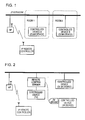
- Fig. 1 schematically shows an example structure of a remote control system according to an embodiment of the present invention.
- the system shown in Fig. 1 includes an IP remote controller used by a user to operate devices, and controlled devices A and B to be operated by the IP remote controller.
- the controlled devices A and B are located in different rooms 1 and 2, respectively, and both devices do not simultaneously reside in an area where infrared light reaches.
- the controlled devices A and B include, for example, a television receiver, a DVD player, and various other devices, such as an AV device, a CE device, and an information device, and are each provided with a function of receiving an infrared command and a network interface.
- the controlled devices A and B are connected to each other via an IP network (LAN) established under IEEE 802.3 (Ethernet (registered trademark)) or the like.
- DLNA Digital Living Network Alliance
- the IP remote controller has a function of transmitting an infrared command in accordance with a user's operation and a wireless network interface, and is capable of communicating with an access point (AP) through a wireless network established under IEEE 802.11a/b or the like. Since the AP is connected to the IP network, the IP remote controller can perform two-way communication with the controlled devices A and B over the AP to transmit a remote control command or receive data from the controlled devices A and B through the IP network.
- AP access point
- the IP remote controller may further include a display, such as an LCD, and may play back and output moving-image data distributed via streaming from the controlled devices A and B through the IP network (discussed below).
- a display such as an LCD
- Fig. 2 shows a remote control system according to another embodiment of the present invention.
- a major difference from the system configuration shown in Fig. 1 is the intervention of a remote control server between an IP remote controller and a device to be controlled.
- the remote control server is used by connecting it to a main DLNA device to be controlled by the IP remote controller, such as a television receiver, or, alternatively, is integrally formed with this type of DLNA device.
- a main DLNA device such as a television receiver, or, alternatively, is integrally formed with this type of DLNA device.
- the remote control server has a wired LAN communication function, such as Ethernet, and receives a command from the IP remote controller through the IP network, i.e., the LAN, to transfer an operation command to a device to be controlled by the IP remote controller. If the device to be controlled also has a LAN communication function, the remote control server transfers through the LAN an operation command received from the IP remote controller.
- a wired LAN communication function such as Ethernet
- the remote control server converts an operation command received from the IP remote controller through the LAN into a command format for use in infrared communication such as SIRCS, and performs optical transmission.
- an extension cord such as an AV mouse
- the AV mouse is disclosed in, for example, Japanese Unexamined Patent Application Publication No. 2001-223955 , which has been assigned to the present applicant.
- the remote control server When the remote control server is connected to a television receiver or any other source device of AV content or is integrally formed therewith, the remote control server can also function as a distribution server that distributes the AV content (or any other form of content) to the IP remote controller.
- received audio and video signals are subjected to AV codec conversion into a low-bit-rate data format that can be received and played back by the IP remote controller, such as MPEG4 data, and are then distributed to the IP remote controller via streaming through the LAN.
- recorded content recorded at a high bit rate such as MPEG1 or MPEG2 content
- the IP remote controller such as MPEG4 data
- Conversion of bit rates is an example, but not limited to, of the process for conversion into a data format that can be played back and output by the IP remote controller.
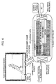
- Fig. 3 shows an example hardware configuration of a terminal device capable of operating as the IP remote controller in the remote control system according to the present embodiment.
- the terminal device shown in Fig. 3 may be manufactured as a dedicated terminal for the IP remote controller, or can be designed to also function as another portable terminal, such as a PDA (Personal Digital Assistant) or a game device.
- PDA Personal Digital Assistant
- An IP remote controller 10 shown in Fig. 3 is configured such that a CPU (Central Processing Unit) 11 generally controls the respective parts via a bus 12.
- a CPU Central Processing Unit
- the CPU 11 is provided with a memory device 13 including a ROM and a RAM, and loads program code stored in the ROM onto the RAM to perform a predetermined process.
- the predetermined process includes operations, such as transmission and reception of a command/response of a control signal to and from a device to be controlled through a network, transmission and reception of content to and from the device to be controlled, file transfer, and remote operation of a device to be controlled, such as a DLNA device or an IR device, and these operations are executed according to an operation input from a user. The details of the operations are discussed below.
- An input switch matrix unit 14 includes a key operation unit including keys, such as a ten-key pad, an audio adjustment key, an image quality adjustment key, and a channel selection key, and is operated to input the contents of an operation to be performed on a device to be remotely controlled by a user.
- a controlled-device operating command input by the input switch matrix unit 14 is transmitted from a network communication unit 15 through an IP network.
- the network communication unit 15 is provided with a network interface for communicating with an access point (AP) through a wireless network established under, for example, IEEE 802.11a/b or the like.
- the network communication unit 15 is assigned identification information unique on the network, such as a MAC address or an IP address.
- the network communication unit 15 is configured to transfer a remote control request in accordance with an instruction given by the input switch matrix unit 14 to a device to be controlled through the network.
- An infrared communication unit 16 is configured to transmit as an infrared signal a device search request for specifying a device in front of the eyes of the user who is an owner of the IP remote controller.
- the infrared communication unit 16 may also be provided with a function for transmitting a standard infrared command with the use of SIRCS (Serial Infrared Remote Control System), which is an infrared communication standard widely used for remote controllers for AV devices and so forth.
- SIRCS Serial Infrared Remote Control System
- a codec processing unit 17 performs encoding and decoding of AV content.
- AV content received by the network communication unit 15 from a device to be controlled can be decoded to play back and output audio and video.
- a television receiver to be operated by the remote controller distributes moving-image data subjected to reception processing, such as a child view, to the IP remote controller through the IP network so that the child view can be viewed on a display screen of the IP remote controller.
- the encoding function of the codec processing unit 17 is not essential.
- a graphic display processor (GDP) 18 processes graphic data to be displayed and outputted to a liquid crystal display unit (LCD) 19, and controls the driving of the LCD 19. For example, a video signal decoded by the codec processing unit 17 is displayed and output from a screen of the LCD 19 by the GDP 18. Further, based on device information obtained from a device to be controlled connected to the network, a user interface for operating the device to be controlled is displayed and output on the LCD 19.
- GDP graphic display processor
- the IP remote controller further includes a data input/output interface 20 formed of a wired interface, such as USB (Universal Serial Bus), a slot for a memory card, or the like.
- AV content transferred through the USB interface or AV content stored in the memory card can be decoded by the codec processing unit 17 to play back and output data.
- data processed on the IP remote controller can be encoded by the codec processing unit 17 to transfer the data from the USB interface or write it in the memory card.
- Fig. 4 schematically shows a structure of an apparatus operating as the remote control server in the remote control system according to the present embodiment.
- the remote control server is used by connecting it to a main AV device to be controlled by the IP remote controller, such as a television receiver, or, alternatively, is integrally formed with this type of AV device.
- a remote control server 30 shown in Fig. 4 is configured such that a CPU 31 generally controls the respective parts via a bus 32.
- the CPU 31 is provided with a memory device 33 including a ROM and a RAM, and loads program code stored in the ROM onto the RAM to perform a predetermined process.
- the remote control server 30 includes a wired LAN communication unit 34, such as Ethernet, and receives a command from the IP remote controller through the LAN and the AP to perform processing on the operation command.
- a wired LAN communication unit 34 such as Ethernet
- the remote control server 30 further includes an infrared processing unit 35.
- the infrared processing unit 35 converts an operation command received from the IP remote controller through the LAN into a command format for use in infrared communication such as SIRCS, and performs optical transmission by means of infrared light. If the legacy controlled device is in a dead angle from the remote control server or the distance therebetween is long, an infrared command is output to an AV mouse so that the infrared command is optically transmitted in the vicinity of the legacy controlled device through output.
- a codec processing unit 37 performs encoding and decoding of AV content.
- the codec processing unit 37 is provided with input terminals for audio and video signals, and encodes audio and video signals input from a device to be controlled, such as a television receiver or an analog video recorder, into a data format that can be played back on the IP remote controller, such as MPEG4 data, to distribute the encoded data to the IP remote controller through the IP network.
- a device to be controlled such as a television receiver or an analog video recorder
- the codec processing unit 37 loads recorded content recorded at a high bit rate, such as MPEG1 or MPEG2 content, from an HDD recorder serving as a device to be controlled through the LAN, converts it into a low-bit-rate data format that can be received and played back by the IP remote controller, such as MPEG4 data, and distributes the converted data via streaming through the LAN.
- a high bit rate such as MPEG1 or MPEG2 content
- the remote control server 30 may further include a large-capacity storage device 38, such as an HDD, for storing encoded or decoded AV content, EPG data separated from a received broadcast wave, and a large volume of other data.
- a large-capacity storage device 38 such as an HDD, for storing encoded or decoded AV content, EPG data separated from a received broadcast wave, and a large volume of other data.
- the HDD 38 is not essential to the remote control server 30.
- a remote control system using an IP remote controller by connecting the IP remote controller and a device to be controlled through a network, communication operations, such as communication of a control signal and content and file transfer, can be performed between the IP remote controller and the device to be controlled. These communication operations are performed, thereby achieving the following basic functions:
- a playback function that is expected as a result of control, such as displaying of network content (a moving picture or still image) on a screen of the remote controller in hand. Further, to realize a control function using meta-information of the content. As an example, a channel is selected (a channel is changed) or a recording reservation is set using EPG information displayed in hand.
- a storage device or a slot for a removable medium such as a memory card
- a content playback apparatus on the network to play back it.
- a picture stored in a memory medium loaded in the remote controller is displayed on a television screen on the network.
- IP remote controllers There are roughly two types of IP remote controllers, i.e., a type having only a control function and a type having a content playback function in addition to the control function.
- the former type i.e., an inexpensive remote controller, and a highly value-added remote controller can individually be constructed.
- the IP remote controller shown in Fig. 3 corresponds to the latter type.
- EPG Electrical Program Guide
- VBI Very Blanking Interval
- DSS Digital Satellite System
- Either type of EPG system provides an EPG view received by a television set on the screen, and allows a user to check a desired program on the basis of the EPG view to select a channel or set a reservation to record the program on the EPG view.
- EPG data received by a television set can be used on an IP remote controller to switch television channels and further set a recording reservation on the EPG view displayed on the LCD 19 of the IP remote controller.
- a television set and an HDD recorder are provided as devices to be controlled by the IP remote controller.
- the television set is a DLNA device having a network communication function, such as Ethernet
- the HDD recorder is an IR device without a network communication function, which can be remotely controlled only by a SIRCS-based infrared communication method.
- the television set is connected to or integrally formed with the remote control server (see Fig.
- Fig. 5 illustrates a manner in which EPG (current) data received by the television set is obtained by the IP remote controller and is displayed on the LCD 19.
- IP remote controller On the side of the IP remote controller, Set EPG View is entered via the input switch matrix unit 14. In response to this, a request for EPG (current) data is transmitted from the IP remote controller to the television receiver, which is a DLNA device, through the network.
- EPG current
- the EPG (current) data superimposed on the received broadcast wave is separated and transferred to the IP remote controller through the network.
- the EPG data is written in a structure description language, such as an XML (eXtensible Markup Language).
- a structure description language such as an XML (eXtensible Markup Language).
- the CPU 11 analyzes the received EPG (current) data to create an EPG view.
- the GDP 18 performs display processing of an EPG (current) view to display and output an EPG view on the LCD 19, as illustrated in Fig. 5 .
- Fig. 6 illustrates a manner in which a television channel change operation is carried out through the EPG (current) view displayed on the IP remote controller.
- the user can select a channel on the EPG (current) display view by using the input switch matrix unit 14.
- a channel change request is transmitted to the television receiver through the network.
- the television receiver adjusts a tuner to the channel specified in the received channel change request. Then, the television receiver notifies the IP remote controller of completion of the channel change through the network.
- the display screen of the LCD 19 is returned to the EPG (current) view.
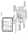
- Fig. 7 illustrates a manner in which EPG (future) data received by the television set is obtained by the IP remote controller and is displayed on the LCD 19.
- IP remote controller On the side of the IP remote controller, Set EPG View is entered via the input switch matrix unit 14. In response to this, a request for EPG (future) data is transmitted from the IP remote controller to the television receiver, which is a device to be controlled, through the network.
- EPG electronic program guide
- the EPG (future) data superimposed on the received broadcast wave is separated and transferred to the IP remote controller through the network.
- the CPU 11 analyzes the received EPG (future) data to create an EPG view.
- the GDP 18 performs display processing of an EPG (future) view to display and output an EPG view on the LCD 19, as illustrated in Fig. 7 .
- Fig. 8 illustrates a manner in which a recording reservation of a program is set through an EPG (future) view displayed on the IP remote controller.
- the user can select on the EPG (future) display view a television program to be reserved for recording by using the input switch matrix unit 14.
- EPG electronic program guide
- the HDD recorder serving as a device to be controlled is an IR device that can be operated only by an old infrared remote control method.
- the remote control server converts an operation command received from the IP remote controller through the network into a command for use in infrared communication such as an SIRCS, and performs optical transmission by means of infrared light. If the IR device is in a dead angle from the remote control server or the distance therebetween is long, an infrared command may be output to an AV mouse so that the infrared command is optically transmitted in the vicinity of the IR device. Meanwhile, if the HDD recorder is near the IP remote controller so as to be directly irradiated with infrared light, the IP remote controller may transmit an SIRCS command for requesting a recording reservation from the infrared communication unit 16.
- Fig. 9 shows an operation sequence for displaying the EPG (current) data on the IP remote controller.
- the remote control server connected to the television receiver stores weekly SI (Service Information) data as EPG data.
- Current SI data superimposed on a received broadcast wave is separated and is stored as EPG data.
- IP remote controller On the side of the IP remote controller, Set EPG View is entered via the input switch matrix unit 14. In response to this, a request for EPG (current) data is transmitted from the IP remote controller to the television receiver, which is a DLNA device, through the network.
- EPG current
- the remote control server transfers the EPG (current) data to the IP remote controller through the network.
- the CPU 11 analyzes the received EPG (current) data to create an EPG view.
- the GDP 18 performs display processing of an EPG (current) view to display and output an EPG view on the LCD 19.
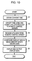
- Fig. 10 is a flowchart showing a processing procedure executed by the IP remote controller to display the EPG (current) data.
- step S2 a time zone is specified, and an EPG data request is transmitted to the remote control server (step S2).
- the CPU 11 configures display data of an EPG view based on the EPG data (step S4).
- the GDP 18 outputs the generated display data on the screen of the LCD 19 (step S5).
- the IP remote controller can obtain EPG (future) data.
- EPG electronic program guide
- a recording reservation of a television program can be set through the EPG (future) view.
- a recording device such as an HDD recorder
- IR device without a network communication function, which can be remotely controlled only by an infrared communication method such as SIRCS.
- Fig. 11 shows an example of an operation sequence in which a recording reservation of a program is set in the IR recording device by the IP remote controller using EPG (future) data.
- EPG electronic program guide
- the remote control server connected to the television receiver stores weekly SI data as EPG data.
- Current SI data superimposed on a received broadcast wave is separated and stored as EPG data.
- the remote control server transfers the EPG (future) data to the IP remote controller through the network. Then, on the side of the IP remote controller, the CPU 11 analyzes the received EPG (future) data to create an EPG view. Then, the GDP 18 performs display processing of an EPG (future) view to display and output an EPG view on the LCD 19.
- the remote control server analyzes the received recording reservation request to determine whether or not overlapping reservations to record the same program have been requested. If overlapping reservations are found, the remote control server returns a reservation-overlap status to the IP remote controller through the network. On the side of the IP remote controller, an error indication is displayed through the LCD 19.
- the remote control server adds the requested recording reservation as a new entry in the recording-reservation list managed in the remote control server. Then, a completion-of-reservation status is returned to the IP remote controller through the network. On the side of the IP remote controller, a completion-of-reservation indication is displayed through the LCD 19.
- the remote control server stands by until the reserved recording time.
- the remote control server transmits an SIRCS command for turning on the power supply to the IR recording device to start the recording of the television program reserved for recording.
- the remote control server transmits an SIRCS command for stopping the recording operation and then an SIRCS command for turning off the power supply to the IR recording device to terminate the overall recording reservation operation.
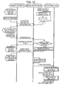
- Fig. 12 shows another example of the operation sequence in which a recording reservation of a program is set in the recording device by the IP remote controller using EPG (future) data.
- EPG electronic program guide
- the remote control server connected to the television receiver stores weekly SI data as EPG data.
- Current SI data superimposed on a received broadcast wave is separated and stored as EPG data.
- the remote control server transfers the EPG (future) data to the IP remote controller through the network. Then, on the side of the IP remote controller, the CPU 11 analyzes the received EPG (future) data to create an EPG view. Then, the GDP 18 performs display processing of an EPG (future) view to display and output an EPG view on the LCD 19.
- the remote control server analyzes the received recording reservation request to determine whether or not overlapping reservations to record the same program have been requested. If overlapping reservations are found, the remote control server returns a reservation-overlap status to the IP remote controller through the network. On the side of the IP remote controller, an error indication is displayed through the LCD 19.
- the remote control server adds the requested recording reservation as a new entry in the recording-reservation list managed in the remote control server. Then, a completion-of-reservation status is returned to the IP remote controller through the network. On the side of the IP remote controller, a completion-of-reservation indication is displayed through the LCD 19.
- the recording-reservation request command transferred through the IP network is subjected to IP/IR protocol conversion to produce an infrared communication command, such as SIRCS, to transfer the reservation data to the recording device.
- the reservation data includes meta-information obtained from the EPG, such as the name of a television program to be reserved for recording, the recording date and time, and the broadcast station.
- the recording device Upon receiving recording-reservation data, the recording device adds the requested recording reservation as a new entry in the recording-reservation list managed in the recording device.
- the power supply of the recording device is turned on to start the recording of the television program reserved for recording.
- the recording device stops the recording operation, and turns off the power supply to terminate the overall recording reservation operation.
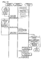
- Fig. 13 shows still another example of the operation sequence in which a recording reservation of a program is set in the recording device by the IP remote controller using EPG (future) data.
- EPG electronic program guide
- the remote control server connected to the television receiver stores weekly SI data as EPG data.
- Current SI data superimposed on a received broadcast wave is separated and stored as EPG data.
- the remote control server transfers the EPG (future) data to the IP remote controller through the network. Then, on the side of the IP remote controller, the CPU 11 analyzes the received EPG (future) data to create an EPG view. Then, the GDP 18 performs display processing of an EPG (future) view to display and output an EPG view on the LCD 19.
- the remote control server performs IP/IR protocol conversion on the recording-reservation request command transferred through the IP network to produce an infrared communication command, such as SIRCS, and transfers the reservation data to the recording device.
- the reservation data includes meta-information obtained from the EPG, such as the name of a television program to be reserved for recording, the recording date and time, and the broadcast station.
- the remote control server returns a status indicating completion of the transfer of the recording-reservation request to the IP remote controller through the network.
- the recording device upon receiving reservation data via infrared communication, it is analyzed to determine whether or not overlapping reservations to record the same program have been requested. If overlapping reservations are found, an error indication is displayed. If there is no overlapping request for making recording reservations, the requested recording reservation is added as a new entry in the recording-reservation list managed in the recording device, and a completion-of-reservation indication is displayed.
- the recording device When the reserved recording time arrives, the recording device turns on the power supply to start the recording of the program reserved for recording.
- the recording device stops the recording operation, and then turns off the power supply to terminate the overall recording reservation operation.
- the IP remote controller has a codec processing function and a graphic display function, and is capable of playing back a moving image.
- the IP remote controller decodes AV content distributed from a television receiver, a remote control server, or the like, which is a device to be controlled, to output audio and video.
- the remote control server or the like encodes an audio signal and video signal received as analog broadcast waves into a data format that can be played back on the IP remote controller, such as MPEG4 data, to distribute the encoded data to the IP remote controller through the IP network.
- the remote control server loads recorded content recorded at a high bit rate, such as MPEG1 or MPEG2 content, from an HDD recorder through the LAN, converts it into a low-bit-rate data format that can be received and played back by the IP remote controller, such as MPEG4 data, and distributes the converted data via streaming through the LAN.
- a television set and an HDD recorder are provided as devices to be controlled by the IP remote controller.
- the television set is a DLNA device having a network communication function, such as Ethernet
- the HDD recorder is an IR device without a network communication function, which can be remotely operated only by a SIRCS-based infrared communication method.
- the television set is connected to or integrally formed with the remote control server (see Fig.
- an operation command from the IP remote controller to the HDD recorder is received through the network and is subjected to protocol conversion by the remote control server to transfer the converted command to the HDD recorder by means of an infrared communication method.
- the remote control server and the HDD recorder are connected through AV input/output terminals.
- Fig. 14 illustrates a manner in which a terrestrial analog broadcast received by the television set is viewed by using the IP remote controller.
- the television set is selected as a device to be operated through the input switch matrix unit 14.
- a request for turning on the power supply is transmitted from the IP remote controller to the television receiver serving as the device to be controlled, and the power supply of the television set is turned on in response to the request.
- a channel is selected through the input switch matrix unit 14.
- a desired channel is determined, television viewing is set.
- a moving-image transfer request is transmitted from the IP remote controller to the television set.
- an analog broadcast wave of the channel in which the viewing is set is received.
- the analog video and audio signals are converted into a data format that can be handled by the IP remote controller, such as MPEG4 data, and are then distributed via streaming to the IP remote controller.
- the IP remote controller decodes the thus transferred moving-image data to display the television program on the LCD 19.
- the operation of displaying a television program currently being viewed on the television set or streaming video from the recording device on the IP remote controller is also referred to herein as a "catch".
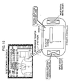
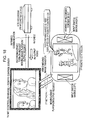
- Figs. 15 to 16 illustrate a manner in which a channel is changed in a period of time during which a terrestrial analog broadcast received by the television set is viewed on the IP remote controller. It is assumed that the television set has a multi-tuner function capable of receiving broadcast waves from two or more channels at the same time.
- the television set encodes a received broadcast program and distributes it to the IP remote controller via streaming, and the IP remote controller receives and decodes it to display the television program on the LCD 19. At this time, the same program is being displayed on the television screen and the LCD 19 of the IP remote controller.
- a channel is selected through the input switch matrix unit 14. For example, if the IP remote controller is provided with a user interface, an operation for selecting the television set as the medium and placing a cursor position onto a desired channel is performed (not shown).
- a channel-change request is transmitted from the IP remote controller to the television set.
- the television set receives an analog broadcast wave on the determined channel, converts it into a data format that can be handled by the IP remote controller, such as MPEG4 data, and distributes the converted data to the IP remote controller via streaming.
- IP remote controller such as MPEG4 data
- the television set still displays the program received on the initial channel.
- the IP remote controller Since the channel change is carried out on the IP remote controller, the television set still displays the program received on the initial channel. On the side of the IP remote controller, meanwhile, since the transferred moving-image data is decoded and displayed on the LCD 19, the television program of the changed channel can be viewed.
- Fig. 17 illustrates a manner in which the video displayed on the television set is changed to the television program currently being viewed on the IP remote controller.
- a screen change request for changing to the channel currently being viewed on the IP remote controller is transmitted to the television set.
- the television set changes the screen to the designated channel, and displays the video of the television program of the changed channel.
- the currently received analog video and audio signals are converted into a data format that can be handled by the IP remote controller, such as MPEG4 data, and is distributed to the IP remote controller via streaming.
- the IP remote controller decodes the thus transferred moving-image data to display the television program on the LCD 19. As a result, the same program is displayed on the television screen and the LCD 19 of the IP remote controller.
- Figs. 18 to 19 illustrate a manner in which recorded content stored in the recording device is viewed on the IP remote controller.
- the user uses the input switch matrix unit 14 to give instructions to turn on the recording device, such as an HDD recorder, and to distribute recorded content. These requests are transmitted to the remote control server integrally formed with the television receiver through the network.
- the recording device such as an HDD recorder
- the HDD recorder which is the device to be controlled, is an IR device that can be operated only by an infrared remote control method.
- the remote control server performs IP/IR conversion on an operation command received from the IP remote controller through the network into a command for use in infrared communication such as SIRCS, and performs optical transmission by means of infrared light. If the legacy controlled device is in a dead angle from the remote control server or the distance therebetween is long, an infrared command is output to an AV mouse so that the infrared command is optically transmitted in the vicinity of the IR device. Meanwhile, if the HDD recorder is near the IP remote controller so as to be directly irradiated with infrared light, the IP remote controller may output an SIRCS command for requesting a recording reservation from the infrared communication unit 16.
- the HDD recorder In response to the SIRCS command, the HDD recorder turns on the power supply thereof, and supplies AV output video of the designated recorded content to the remote control server.
- the remote control server encodes the AV output video of the HDD recorder into a data format that can be played back by the IP remote controller, such as MPEG4 data, and distributes it to the IP remote controller through the IP network.
- the remote control server loads recorded content recorded at a high bit rate, such as MPEG1 or MPEG2 content, from the HDD recorder, converts it into a low-bit-rate data format that can be received and played back by the IP remote controller, such as MPEG4 data, and distributes the converted data via streaming through the LAN.
- the transferred moving-image data is decoded and displayed on the LCD 19, thus allowing the user to view the recorded content.
- the television set on the other hand, still displays the program received on the initial channel.
- a screen change request for changing to the recorded content currently being viewed on the IP remote controller is transmitted to the television set.
- the AV output video from the HDD recorder is encoded and distributed to the IP remote controller while the display screen is also changed from the television video to the AV output video.
- Fig. 20 shows an example of an operation sequence for distributing AV content via streaming from an IR recording device that can be remotely controlled only by an infrared communication method to the IP remote controller.
- a remote control server having a network connection function and a protocol conversion function into an infrared command is provided.
- the remote control server is connected to or integrally formed with, for example, a television set. Further, it is assumed that the remote control server pre-registers therein information concerning IR devices to which an infrared command can be transmitted from the remote control server.
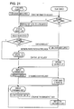
- the IP remote controller when turned on, submits a request for device information concerning the IR devices to the remote control server through the network.
- the remote control server In response to the request for the device information, the remote control server returns the information concerning the IR devices to the IP remote controller through the network.
- the received device list is displayed on the LCD 19 of the IP remote controller.
- a request for starting streaming of AV content to the selected IR device is transmitted to the remote control server through the network.
- the remote control server Upon receiving the request for starting streaming, the remote control server determines whether or not the requested IR device has been turned on and is outputting video. If the IR device has not been turned on, the IR device is turned on to start outputting video.
- the remote control server encodes the AV output video from the IR device into a data format that can be played back by the IP remote controller, such as MPEG4 data, and distributes it to the IP remote controller via streaming through the IP network.
- the IP remote controller decodes the thus transferred moving-image data to display video on the LCD 19.
- operations for the IR device can be performed through the input switch matrix unit 14.
- the operations used herein include changing of output video, changing of channels, and so forth.
- a command for the IR device is transmitted from the IP remote controller to the remote control server through the network.
- the remote control server converts the operation command received from the IP remote controller through the network into a command for use in infrared communication such as SIRCS, and performs optical transmission by means of infrared light.
- the IR device executes the command received via infrared light. Then, streaming of video in which the execution result of the command has been reflected is performed via the remote control server.
- the device to be controlled by the IP remote controller is an IR device that can be remotely controlled only by an infrared communication method, as discussed above, a remote control server for performing protocol conversion on a command is provided. If the device to be controlled is a DLNA device having a network connection function, meanwhile, the intervention of the remote control server is not necessary because the IP remote controller is capable of performing a command operation through the network.
- Fig. 21 shows an example of an operation sequence for streaming AV content from a DLNA device to the IP remote controller.
- the IP remote controller when turned on, submits a request for device information to the DLNA device through the network.
- the DLNA device In response to the device information request, the DLNA device, which has been turned on, returns the device information to the IP remote controller through the network.
- a device list concerning DLNA devices that have responded is displayed on the screen of the LCD 19 of the IP remote controller.
- a DLNA device that responded with device information in the past is displayed grayed-out.
- a DLNA device that has not responded for a predetermined period of time is determined to be disconnected from the network and is deleted from the device list.
- the user selects a DLNA device on the screen, it is determined whether or not the selected DLNA device has been turned on, that is, whether or not the device information has been returned. If the DLNA device has not been turned on, a request for turning on the power supply is transmitted to the DLNA device through the network.
- the DLNA device Upon receiving the request for turning on the power supply, the DLNA device turns on the power supply, and returns a network participation notification to the IP remote controller.
- the IP remote controller reflects the activation of the DLNA device in the device list, and changes the grayed-out indication of the DLNA device to a normal indication.
- the DLNA device If the selected DLNA device has been turned on, a request for a list of available content is submitted to the selected DLNA device through the network. In response to this, the DLNA device returns a content list to the IP remote controller.
- the content list is a list of recorded content if the DLNA device is a recording device, such as an HDD recorder, and is a list of receivable channels if the DLNA device is a television set.
- the received content list is displayed on the screen of the LCD 19 of the IP remote controller.
- a request for starting streaming of the selected content is transmitted to the remote control server through the network.
- the DLNA device Upon receiving the request for starting streaming, the DLNA device outputs the corresponding video, and encodes the AV output video into a data format that can be played back by the IP remote controller, such as MPEG4 data, to distribute the encoded data to the IP remote controller via streaming through the IP network.
- the IP remote controller such as MPEG4 data
- the IP remote controller decodes the thus transferred moving-image data to display video on the LCD 19.
- operations for the content can be performed through the input switch matrix unit 14.
- the operations for the content used herein include changing of output video, changing of channels, and so forth.
- a command for the content operations is sent from the IP remote controller to the DLNA device through the network.
- the DLNA device executes the received command to perform streaming of video in which the execution result of the command has been reflected.
- Fig. 22 shows an example of an operation sequence for "throwing" content of an IR device currently being viewed on the IP remote controller onto a television set. It is assumed that the television set has a remote control server function.
- AV video is output from an IR recording device, such as an HDD recorder or any other recording device.
- the television set utilizes the remote control server function to encode the AV output video into a data format that can be played back by the IP remote controller, such as MPEG4 data, to distribute the encoded data to the IP remote controller via streaming through the IP network.
- the IP remote controller decodes the transferred moving-image data to display video on the LCD 19.
- IP remote controller instructs the television set to stop streaming, and the television set stops streaming to the IP remote controller in response to the instruction.
- the IP remote controller instructs the television set to play back the content of the IR device.
- content is specified and played back; there are several sets by which the content is specified, such as a device, which is a content provider, and a display destination, the name of an AV input terminal of the television set and a display destination, and a function name of the television set and a display destination.
- AV output video from the IR recording device is displayed and output.
- FIG. 21 video content output from the DLNA device can directly be viewed on the IP remote controller.
- FIG. 23 shows an example of an operation sequence for "throwing" content of a DLNA device currently being viewed on the IP remote controller onto a television set.
- An HDD recorder or any other DLNA device having a recording function encodes AV output video into a data format that can be played by the IP remote controller, such as MPEG4 data, and distributes the encoded data to the IP remote controller via streaming through the IP network.
- the IP remote controller decodes the transferred moving-image data to display video on the LCD 19.
- the IP remote controller instructs the DLNA device to stop streaming to the IP remote controller. In response to the instruction, the DLNA device stops streaming to the IP remote controller.
- the IP remote controller submits a content playback instruction through the network.
- a content playback instruction a server, a content name, a playback start point, and a display destination are specified.
- the television set specified as the destination onto which the content is thrown requests the DLNA device to perform streaming.
- the DLNA device starts streaming of the specified content from the specified playback start point.
- the television set displays and outputs the received streaming video.
- While a device to be controlled by an IP remote controller has been described herein in the context of a television receiver or a recording device such as an HDD recorder, the present invention is not limited thereto. Other devices handling AV content, or home electric appliances or information devices that do not handle AV content may also be used as devices to be controlled by the IP remote controller to construct the remote control system according to the present invention.
Landscapes
- Engineering & Computer Science (AREA)
- Signal Processing (AREA)
- Multimedia (AREA)
- Human Computer Interaction (AREA)
- Computer Networks & Wireless Communication (AREA)
- Marketing (AREA)
- Business, Economics & Management (AREA)
- Computer Security & Cryptography (AREA)
- Physics & Mathematics (AREA)
- General Physics & Mathematics (AREA)
- Databases & Information Systems (AREA)
- Selective Calling Equipment (AREA)
- Details Of Television Systems (AREA)
Claims (26)
- Système de télécommande comprenant une télécommande (10) et un ou plusieurs dispositifs à commander, dans lequel ladite télécommande (10) est utilisée pour exploiter lesdits un ou plusieurs dispositifs à commander,
dans lequel ladite télécommande (10) et au moins certains des dispositifs à commander sont dotés d'une fonction de communication de réseau, et un dispositif à commander est adapté pour être exploité au moyen d'une commande par le biais d'un réseau en réponse à une entrée d'utilisateur sur la télécommande (10) ;
dans lequel la télécommande (10) est adaptée pour soumettre une requête d'informations de dispositifs concernant les dispositifs à commander, par le biais du réseau, et afficher une liste de dispositifs concernant un dispositif à commander comportant des informations de dispositifs obtenues en réponse à la requête ;
dans lequel :ladite télécommande (10) et lesdits au moins certains des dispositifs à commander sont dotés d'une fonction de communication de réseau, la télécommande (10) est configurée pour exécuter une communication bidirectionnelle avec lesdits au moins certains des dispositifs sur un réseau IP, et ledit dispositif à commander est adapté pour être exploité au moyen de commandes reçues sur un réseau IP,la télécommande (10) est adaptée pour soumettre par l'intermédiaire du réseau IP, aux dispositifs à commander ayant la fonction de communication de réseau, une requête d'informations de dispositifs,les dispositifs à commander ayant la fonction de communication de réseau et qui ont été mis en marche sont adaptés pour répondre à ladite requête d'informations de dispositifs reçue depuis la télécommande (10) en renvoyant des informations de dispositifs à la télécommande (10) par le biais du réseau IP ;la télécommande (10) est adaptée pour déterminer les dispositifs qui répondent présentement à une requête d'informations de dispositifs provenant de la télécommande, les dispositifs qui ne répondent pas actuellement à une requête d'informations de dispositifs provenant de la télécommande mais qui ont répondu à une requête d'informations de dispositifs provenant de la télécommande dans le passé, et les dispositifs qui n'ont pas répondu à une requête d'informations de dispositifs provenant de la télécommande pendant une période de temps prédéterminée, et afficher sur la liste d'affichage un dispositif à commander qui a répondu avec des informations de dispositifs actuellement, afficher un dispositif à commander qui a répondu avec des informations de dispositifs dans le passé et qui ne répond pas actuellement d'une manière estompée sur la liste de dispositifs, et effacer de la liste de dispositifs un dispositif à commander qui n'a pas répondu à une requête d'informations de dispositifs provenant de la télécommande pendant une période de temps prédéterminée ; etquand un dispositif à commander affiché de manière estompée sur la liste de dispositifs est sélectionné, la télécommande est adaptée pour transmettre une requête d'opération après avoir soumis une requête de mise en marche du dispositif à commander. - Système de télécommande selon la revendication 1, dans lequel le dispositif à commander est configuré pour renvoyer une réponse par le biais du réseau IP en réponse à une commande transmise par la télécommande (10) par le biais du réseau IP.
- Système de télécommande selon la revendication 1, dans lequel la télécommande (10) soumet une requête de données au dispositif à commander, et le dispositif à commander renvoie les données requises par le biais du réseau IP.
- Système de télécommande selon la revendication 3, dans lequel la télécommande (10) est configurée pour reproduire et produire en sortie les données reçues depuis le dispositif à commander.
- Système de télécommande selon la revendication 4, dans lequel le dispositif à commander est configuré pour convertir les données requises par la télécommande (10) dans un format pouvant être reproduit et produit en sortie par la télécommande, et renvoyer les données converties par le biais du réseau IP.
- Système de télécommande selon la revendication 1, dans lequel :le dispositif à commander comporte un dispositif IR qui peut être télécommandé uniquement par communication infrarouge, et un serveur de télécommande ayant une fonction de communication de réseau et une fonction de conversion de protocole pour convertir une commande reçue par le biais du réseau IP en une commande infrarouge ; etle serveur de télécommande est adapté pour recevoir une commande d'opération pour le dispositif IR depuis la télécommande (10) par le biais du réseau IP, convertir la commande d'opération en une commande infrarouge, et transférer la commande infrarouge au dispositif IR.
- Système de télécommande selon la revendication 6, dans lequel le serveur de télécommande est adapté pour extraire du dispositif IR les données requises par la télécommande (10) et les envoyer au dispositif IR, et convertir les données extraites dans un format pouvant être reproduit et produit en sortie par la télécommande pour renvoyer les données converties à la télécommande par le biais du réseau IP.
- Système de télécommande selon la revendication 4, dans lequel :le dispositif à commander est adapté pour stocker des données EPG, et renvoyer les données EPG à la télécommande par le biais du réseau IP en réponse à une requête de données EPG provenant de la télécommande ; etla télécommande (10) est adaptée pour afficher et produire en sortie les données EPG reçues.
- Système de télécommande selon la revendication 8, dans lequel la télécommande (10) est adaptée pour transmettre une requête de changement de canal à un récepteur de télévision servant de dispositif à commander en réponse à une désignation d'un canal sur une vue d'affichage de données EPG courante.
- Système de télécommande selon la revendication 9, dans lequel :le dispositif à commander est adapté pour convertir un contenu vidéo reçu sur le canal spécifié dans la requête de changement donnée par la télécommande (10) dans un format pouvant être reproduit et produit en sortie par la télécommande, et distribuer le contenu vidéo converti à la télécommande par diffusion continue par le biais du réseau IP ; etla télécommande (10) est adaptée pour décoder le contenu vidéo reçu, et afficher la vidéo.
- Système de télécommande selon la revendication 9, dans lequel le récepteur de télévision servant de dispositif à commander est adapté pour changer l'affichage de la vidéo sur le canal spécifié dans la requête de changement donnée par la télécommande (10).
- Système de télécommande selon la revendication 8, dans lequel la télécommande (10) est adaptée, en réponse à la désignation d'un programme sur une vue d'affichage de données EPG futures, transmettre une requête pour établir une réservation pour enregistrer le programme sur un dispositif d'enregistrement servant de dispositif à commander.
- Système de télécommande selon la revendication 6, dans lequel :le serveur de télécommande est adapté, à la réception d'une requête de réservation d'enregistrement provenant de la télécommande (10) par le biais du réseau, convertir la requête de réservation d'enregistrement en des données de réservation infrarouge en fonction de données EPG, et transmettre la requête de réservation d'enregistrement par l'intermédiaire d'une lumière infrarouge à un dispositif d'enregistrement IR pouvant être télécommandé uniquement au moyen d'une communication infrarouge ; etle dispositif d'enregistrement IR est adapté pour régler une réservation d'enregistrement en fonction des données de réservation infrarouge depuis le serveur de télécommande.
- Système de télécommande selon la revendication 5, dans lequel :un dispositif d'enregistrement servant de dispositif à commander est adapté, en réponse à une requête de contenu vidéo provenant de la télécommande (10), pour convertir le contenu vidéo requis dans un format pouvant être reproduit et produit en sortie par la télécommande (10), et distribuer le contenu vidéo converti par diffusion continue par le biais du réseau IP ; etla télécommande (10) est adaptée pour décoder le contenu vidéo reçu, et afficher la vidéo.
- Système de télécommande selon la revendication 6, dans lequel :le serveur de télécommande est adapté pour, à la réception d'une requête de contenu vidéo depuis la télécommande (10) par le biais du réseau IP, convertir la requête de contenu vidéo en une commande infrarouge, et transmettre la requête de contenu vidéo par l'intermédiaire d'une lumière infrarouge à un dispositif d'enregistrement IR pouvant être télécommandé uniquement au moyen d'une communication infrarouge ;le dispositif d'enregistrement IR est adapté pour produire en sortie un contenu vidéo en fonction de la commande infrarouge provenant du serveur de télécommande ; etle serveur de télécommande est adapté pour convertir le contenu vidéo produit en sortie par le dispositif d'enregistrement IR en un format pouvant être reproduit et produit en sortie par la télécommande, et distribuer renvoyer le contenu vidéo converti à la télécommande (10) par diffusion continue par le biais du réseau IP.
- Système de télécommande selon la revendication 14 ou 15, dans lequel :la télécommande (10) est adaptée pour demander à un dispositif d'affichage servant de dispositif à commander de changer l'affichage de la vidéo en un contenu vidéo présentement affiché sur la télécommande ; etle dispositif d'affichage est adapté pour changer l'écran sur la vidéo produite en sortie par le dispositif d'enregistrement en réponse à la requête de changement de l'affichage de la vidéo.
- Système de télécommande selon la revendication 1, dans lequel la télécommande (10) est adaptée pour transmettre une requête d'opération à un dispositif à commander sélectionné sur la liste de dispositifs.
- Système de télécommande selon la revendication 6, dans lequel :le serveur de télécommande est adapté pour enregistrer des informations de dispositifs IR auxquels la commande infrarouge peut être transmise, et renvoyer des informations de dispositifs IR à la télécommande (10) en réponse à une requête provenant de la télécommande ; etla télécommande (10) est adaptée pour afficher une liste de dispositifs IR.
- Système de télécommande selon la revendication 18, dans lequel :la télécommande (10) est adaptée pour transmettre une requête d'opération pour un dispositif IR sélectionné sur la liste de dispositifs IR au serveur de télécommande par le biais du réseau IP ; etle serveur de télécommande est adapté pour convertir la requête d'opération pour le dispositif IR provenant de la télécommande en une commande infrarouge, et transférer la commande infrarouge convertie au dispositif IR.
- Télécommande (10) pour exploiter à distance un ou plusieurs dispositifs à commander, comprenant :une unité de communication de réseau (15) adaptée pour exécuter une opération de communication par le biais d'un réseau ;une unité d'entrée d'utilisateur (14) adaptée pour recevoir une entrée d'instruction depuis un utilisateur ;une unité de traitement de données (11) adaptée pour traiter des données à transmettre à un dispositif à commander et à recevoir de celui-ci par le biais du réseau en fonction de l'entrée d'instruction provenant de l'utilisateur par l'intermédiaire de l'unité d'entrée d'utilisateur ; etune unité de sortie de reproduction de données (17, 18) adaptée pour décoder des données reçues à travers le réseau pour reproduire et produire en sortie les données ;la télécommande (10) étant adaptée pour soumettre une requête d'informations de dispositifs concernant les dispositifs à commander par le biais du réseau ; etl'unité de reproduction-sortie de données (17, 18) est adaptée pour afficher une liste de dispositifs concernant un dispositif à commander comportant des informations de dispositifs obtenues en réponse à la requête ;dans laquelle :l'unité de communication de réseau (15) est adaptée pour exécuter une communication bidirectionnelle avec lesdits un ou plusieurs dispositifs à commander, par le biais d'un réseau IP,la télécommande (10) est adaptée pour soumettre, par le biais du réseau IP, à des dispositifs à commander ayant la fonction de communication de réseau, une requête d'informations de dispositifs, la télécommande (10) est adaptée pour déterminer les dispositifs qui répondent actuellement à une requête d'informations de dispositifs provenant de la télécommande, les dispositifs qui ne répondent pas actuellement à une requête d'informations de dispositifs provenant de la télécommande mais qui ont répondu à une requête d'informations de dispositifs provenant de la télécommande dans le passé, et les dispositifs qui n'ont pas répondu à une requête d'informations de dispositifs provenant de la télécommande pendant une période de temps prédéterminée,l'unité de reproduction-sortie de donnée (17, 18) est adaptée pour afficher sur la liste d'affichage un dispositif à commander qui a répondu actuellement avec des informations de dispositifs, afficher un dispositif à commander qui a répondu avec des informations de dispositifs dans le passé et qui ne répond pas actuellement de manière estompée sur la liste de dispositifs, et supprimer de la liste de dispositifs un dispositif à commander qui n'a pas répondu à une requête d'informations de dispositifs provenant de la télécommande pendant une période de temps prédéterminée ; etla télécommande (10) est adaptée, quand un dispositif à commander affiché de manière estompée sur la liste de dispositifs est sélectionné, transmettre une requête d'opération après qu'une requête de mise en marche du dispositif à commander est soumise.
- Télécommande (10) selon la revendication 20, dans laquelle l'unité de traitement de données (11) est adaptée pour traiter la transmission d'une commande vers un dispositif à commander et la réception d'une réponse depuis celui-ci par le biais du réseau IP.
- Télécommande (10) selon la revendication 20, dans laquelle l'unité de reproduction-sortie de données (17, 18) est adaptée pour afficher et produire en sortie des données EPG reçues.
- Télécommande (10) selon la revendication 22, adaptée pour transmettre une requête de changement de canal à un récepteur de télévision servant de dispositif à commander en réponse à une désignation d'un canal sur une vue d'affichage de données EPG courante.
- Télécommande (10) selon la revendication 20, dans lequel l'unité de reproduction-sortie de données (17, 18) est adaptée pour décoder un contenu vidéo reçu, et afficher la vidéo.
- Télécommande (10) selon la revendication 22, adaptée, en réponse à la désignation d'un programme sur une vue d'affichage de données EPG futures, pour transmettre une requête pour établir une réservation pour enregistrer le programme sur un dispositif d'enregistrement servant de dispositif à commander.
- Télécommande (10) selon la revendication 20, adaptée pour transmettre une requête d'opération à un dispositif à commander sélectionné sur la liste de dispositifs.
Applications Claiming Priority (3)
| Application Number | Priority Date | Filing Date | Title |
|---|---|---|---|
| JP2004372050 | 2004-12-22 | ||
| JP2005017439A JP4207900B2 (ja) | 2004-12-22 | 2005-01-25 | リモコン・システム、リモート・コマンダ、並びにリモコン・サーバ |
| PCT/JP2005/022340 WO2006067954A1 (fr) | 2004-12-22 | 2005-12-06 | Système de commande à distance, commande à distance et serveur de commande à distance |
Publications (3)
| Publication Number | Publication Date |
|---|---|
| EP1830558A1 EP1830558A1 (fr) | 2007-09-05 |
| EP1830558A4 EP1830558A4 (fr) | 2009-10-21 |
| EP1830558B1 true EP1830558B1 (fr) | 2014-04-16 |
Family
ID=36601558
Family Applications (1)
| Application Number | Title | Priority Date | Filing Date |
|---|---|---|---|
| EP05814133.4A Ceased EP1830558B1 (fr) | 2004-12-22 | 2005-12-06 | Système de commande à distance, commande à distance et serveur de commande à distance |
Country Status (5)
| Country | Link |
|---|---|
| US (6) | US10165320B2 (fr) |
| EP (1) | EP1830558B1 (fr) |
| JP (1) | JP4207900B2 (fr) |
| KR (1) | KR20070089765A (fr) |
| WO (1) | WO2006067954A1 (fr) |
Cited By (1)
| Publication number | Priority date | Publication date | Assignee | Title |
|---|---|---|---|---|
| CN104756506A (zh) * | 2012-10-24 | 2015-07-01 | 索尼公司 | 经由ip的hdmi设备控制 |
Families Citing this family (92)
| Publication number | Priority date | Publication date | Assignee | Title |
|---|---|---|---|---|
| US8266657B2 (en) | 2001-03-15 | 2012-09-11 | Sling Media Inc. | Method for effectively implementing a multi-room television system |
| US6263503B1 (en) | 1999-05-26 | 2001-07-17 | Neal Margulis | Method for effectively implementing a wireless television system |
| US9998802B2 (en) | 2004-06-07 | 2018-06-12 | Sling Media LLC | Systems and methods for creating variable length clips from a media stream |
| US7975062B2 (en) | 2004-06-07 | 2011-07-05 | Sling Media, Inc. | Capturing and sharing media content |
| US7769756B2 (en) | 2004-06-07 | 2010-08-03 | Sling Media, Inc. | Selection and presentation of context-relevant supplemental content and advertising |
| US8099755B2 (en) | 2004-06-07 | 2012-01-17 | Sling Media Pvt. Ltd. | Systems and methods for controlling the encoding of a media stream |
| US7917932B2 (en) | 2005-06-07 | 2011-03-29 | Sling Media, Inc. | Personal video recorder functionality for placeshifting systems |
| US8346605B2 (en) | 2004-06-07 | 2013-01-01 | Sling Media, Inc. | Management of shared media content |
| US7647614B2 (en) | 2004-06-07 | 2010-01-12 | Sling Media, Inc. | Fast-start streaming and buffering of streaming content for personal media player |
| US7702952B2 (en) | 2005-06-30 | 2010-04-20 | Sling Media, Inc. | Firmware update for consumer electronic device |
| US7907222B2 (en) | 2005-09-08 | 2011-03-15 | Universal Electronics Inc. | System and method for simplified setup of a universal remote control |
| US11769398B2 (en) | 2005-09-08 | 2023-09-26 | Universal Electronics Inc. | System and method for widget-assisted setup of a universal remote control |
| US7782407B2 (en) * | 2006-02-21 | 2010-08-24 | Mitsubishi Digital Electronics America, Inc. | Smart remote control |
| JP2007336094A (ja) * | 2006-06-13 | 2007-12-27 | Canon Inc | 視聴システム及びその制御方法、視聴装置及びその制御方法、並びに制御プログラム |
| US10013381B2 (en) | 2006-08-31 | 2018-07-03 | Bose Corporation | Media playing from a docked handheld media device |
| JP4588005B2 (ja) * | 2006-09-14 | 2010-11-24 | シャープ株式会社 | 通信端末装置、映像表示装置および制御プログラム |
| US8521806B2 (en) * | 2006-12-14 | 2013-08-27 | Hewlett-Packard Development Company, L.P. | Initiating a file download by a first electrical device through a second electrical device |
| JP2008153896A (ja) * | 2006-12-15 | 2008-07-03 | Nec Corp | コンテンツ配信システム、コンテンツ配信側ユーザー端末、コンテンツ被配信側ユーザー端末、コンテンツ配信システムの認証方法 |
| JP4876962B2 (ja) * | 2007-02-20 | 2012-02-15 | ソニー株式会社 | ネットワークシステム、サービスサーバ、リモート録画予約先録画装置の決定方法、及びコンピュータプログラム |
| CN101646992B (zh) * | 2007-03-28 | 2012-05-30 | 株式会社爱可信 | 内容再现系统、内容再现控制装置 |
| US8477793B2 (en) | 2007-09-26 | 2013-07-02 | Sling Media, Inc. | Media streaming device with gateway functionality |
| JP5194673B2 (ja) | 2007-09-26 | 2013-05-08 | 株式会社日立製作所 | 携帯端末、及び情報の送受信方法 |
| US8350971B2 (en) | 2007-10-23 | 2013-01-08 | Sling Media, Inc. | Systems and methods for controlling media devices |
| KR101421196B1 (ko) * | 2007-10-30 | 2014-07-28 | 삼성전자주식회사 | 디스플레이 장치 및 그 제어방법 |
| JP4999649B2 (ja) * | 2007-11-09 | 2012-08-15 | キヤノン株式会社 | 表示装置 |
| KR101418249B1 (ko) * | 2007-11-20 | 2014-07-11 | 삼성전자주식회사 | Rf id 기능을 갖는 단말기 및 그 정보 처리 방법 |
| US8686834B2 (en) | 2007-11-20 | 2014-04-01 | Samsung Electronics Co., Ltd. | Terminal having radio frequency function and method of processing information of the terminal |
| EP2063350A1 (fr) * | 2007-11-20 | 2009-05-27 | Samsung Electronics Co., Ltd. | Procédé et appareil pour l'interfaçage entre dispositifs d'un réseau domestique |
| US8060609B2 (en) | 2008-01-04 | 2011-11-15 | Sling Media Inc. | Systems and methods for determining attributes of media items accessed via a personal media broadcaster |
| JP5233289B2 (ja) | 2008-01-18 | 2013-07-10 | ソニー株式会社 | 遠隔操作装置、電気機器及び通信システム |
| US8072905B2 (en) | 2008-02-04 | 2011-12-06 | Sony Ericsson Mobile Communications Ab | Intelligent interaction between devices in a local network |
| TW200937955A (en) * | 2008-02-22 | 2009-09-01 | Sampo Corp | Network monitoring system with common storage medium and method thereof |
| US9852615B2 (en) | 2011-03-25 | 2017-12-26 | Universal Electronics Inc. | System and method for facilitating appliance control via a smart device |
| US9088663B2 (en) * | 2008-04-18 | 2015-07-21 | Universal Electronics Inc. | System for appliance control via a network |
| US8667279B2 (en) | 2008-07-01 | 2014-03-04 | Sling Media, Inc. | Systems and methods for securely place shifting media content |
| JP4735677B2 (ja) * | 2008-08-07 | 2011-07-27 | ソニー株式会社 | 携帯情報端末、情報提供方法、情報処理プログラム、情報提供サーバおよび情報提供システム |
| US8139164B2 (en) * | 2008-08-12 | 2012-03-20 | Sony Corporation | Using A/V device to send controlled device communication-related parameters to program remote control |
| US8381310B2 (en) | 2009-08-13 | 2013-02-19 | Sling Media Pvt. Ltd. | Systems, methods, and program applications for selectively restricting the placeshifting of copy protected digital media content |
| US8667163B2 (en) | 2008-09-08 | 2014-03-04 | Sling Media Inc. | Systems and methods for projecting images from a computer system |
| US20100083189A1 (en) * | 2008-09-30 | 2010-04-01 | Robert Michael Arlein | Method and apparatus for spatial context based coordination of information among multiple devices |
| US20100118209A1 (en) * | 2008-11-11 | 2010-05-13 | Sony Corporation | System and method for power saving via context based communication |
| US9191610B2 (en) | 2008-11-26 | 2015-11-17 | Sling Media Pvt Ltd. | Systems and methods for creating logical media streams for media storage and playback |
| KR20100083641A (ko) * | 2009-01-14 | 2010-07-22 | 삼성전자주식회사 | 단말장치, 방송수신장치 및 그 제어 방법 |
| US8438602B2 (en) | 2009-01-26 | 2013-05-07 | Sling Media Inc. | Systems and methods for linking media content |
| JP2010237807A (ja) * | 2009-03-30 | 2010-10-21 | Nec Personal Products Co Ltd | コンテンツ配信システム、管理サーバ、クライアント機器、コンテンツ配信方法およびプログラム |
| US8171148B2 (en) | 2009-04-17 | 2012-05-01 | Sling Media, Inc. | Systems and methods for establishing connections between devices communicating over a network |
| KR20100135145A (ko) * | 2009-06-16 | 2010-12-24 | 삼성전자주식회사 | 원격제어장치 및 그의 디스플레이방법 |
| US8406431B2 (en) | 2009-07-23 | 2013-03-26 | Sling Media Pvt. Ltd. | Adaptive gain control for digital audio samples in a media stream |
| US9479737B2 (en) | 2009-08-06 | 2016-10-25 | Echostar Technologies L.L.C. | Systems and methods for event programming via a remote media player |
| US8966101B2 (en) | 2009-08-10 | 2015-02-24 | Sling Media Pvt Ltd | Systems and methods for updating firmware over a network |
| US8799408B2 (en) | 2009-08-10 | 2014-08-05 | Sling Media Pvt Ltd | Localization systems and methods |
| US8532472B2 (en) | 2009-08-10 | 2013-09-10 | Sling Media Pvt Ltd | Methods and apparatus for fast seeking within a media stream buffer |
| US9565479B2 (en) | 2009-08-10 | 2017-02-07 | Sling Media Pvt Ltd. | Methods and apparatus for seeking within a media stream using scene detection |
| US9525838B2 (en) | 2009-08-10 | 2016-12-20 | Sling Media Pvt. Ltd. | Systems and methods for virtual remote control of streamed media |
| US9160974B2 (en) | 2009-08-26 | 2015-10-13 | Sling Media, Inc. | Systems and methods for transcoding and place shifting media content |
| US8314893B2 (en) | 2009-08-28 | 2012-11-20 | Sling Media Pvt. Ltd. | Remote control and method for automatically adjusting the volume output of an audio device |
| US9015225B2 (en) | 2009-11-16 | 2015-04-21 | Echostar Technologies L.L.C. | Systems and methods for delivering messages over a network |
| KR101642310B1 (ko) * | 2009-11-23 | 2016-07-25 | 엘지전자 주식회사 | 멀티미디어 기기 제어 장치 및 그래픽 사용자 인터페이스 제공방법 |
| US8799485B2 (en) | 2009-12-18 | 2014-08-05 | Sling Media, Inc. | Methods and apparatus for establishing network connections using an inter-mediating device |
| US8626879B2 (en) | 2009-12-22 | 2014-01-07 | Sling Media, Inc. | Systems and methods for establishing network connections using local mediation services |
| US9178923B2 (en) | 2009-12-23 | 2015-11-03 | Echostar Technologies L.L.C. | Systems and methods for remotely controlling a media server via a network |
| US9275054B2 (en) | 2009-12-28 | 2016-03-01 | Sling Media, Inc. | Systems and methods for searching media content |
| US8856349B2 (en) | 2010-02-05 | 2014-10-07 | Sling Media Inc. | Connection priority services for data communication between two devices |
| US8522283B2 (en) | 2010-05-20 | 2013-08-27 | Google Inc. | Television remote control data transfer |
| JP5521774B2 (ja) * | 2010-05-25 | 2014-06-18 | ソニー株式会社 | 情報処理装置、情報処理方法、及びそのプログラム |
| US20120030712A1 (en) * | 2010-08-02 | 2012-02-02 | At&T Intellectual Property I, L.P. | Network-integrated remote control with voice activation |
| US8732697B2 (en) | 2010-08-04 | 2014-05-20 | Premkumar Jonnala | System, method and apparatus for managing applications on a device |
| WO2012064315A1 (fr) * | 2010-11-09 | 2012-05-18 | Thomson Licensing | Systèmes et procédés de commande de décodeur multi-bande d'un dispositif d'affichage |
| US10341711B2 (en) * | 2010-11-10 | 2019-07-02 | Saturn Licensing Llc | Remote controller device with electronic programming guide and video display |
| US8875180B2 (en) * | 2010-12-10 | 2014-10-28 | Rogers Communications Inc. | Method and device for controlling a video receiver |
| US8689269B2 (en) * | 2011-01-27 | 2014-04-01 | Netflix, Inc. | Insertion points for streaming video autoplay |
| JP5607579B2 (ja) | 2011-06-03 | 2014-10-15 | 任天堂株式会社 | 情報処理システム、情報処理装置、情報処理プログラム、およびコンテンツ再生制御方法 |
| CN102892034A (zh) * | 2011-08-12 | 2013-01-23 | 北京多看科技有限公司 | 一种控制视频播放的方法和系统 |
| US9019435B2 (en) | 2011-09-22 | 2015-04-28 | Universal Electronics Inc. | System and method for configuring controlling device functionality |
| KR101834995B1 (ko) * | 2011-10-21 | 2018-03-07 | 삼성전자주식회사 | 디바이스 간 컨텐츠 공유 방법 및 장치 |
| US11295603B2 (en) | 2011-10-28 | 2022-04-05 | Universal Electronics Inc. | System and method for optimized appliance control |
| US11756412B2 (en) | 2011-10-28 | 2023-09-12 | Universal Electronics Inc. | Systems and methods for associating services and/or devices with a voice assistant |
| CN102523403B (zh) * | 2011-12-31 | 2014-07-09 | 四川长虹电器股份有限公司 | 电视机mac地址设置及修改方法 |
| US9418658B1 (en) * | 2012-02-08 | 2016-08-16 | Amazon Technologies, Inc. | Configuration of voice controlled assistant |
| JP5863563B2 (ja) * | 2012-05-17 | 2016-02-16 | 日立マクセル株式会社 | 無線操作制御用プログラム、無線端末、及びコンテンツ視聴システム |
| US9043841B2 (en) * | 2012-08-21 | 2015-05-26 | Sony Corporation | Internet TV module for enabling presentation and navigation of non-native user interface on TV having native user interface using either TV remote control or module remote control |
| TW201431364A (zh) * | 2013-01-28 | 2014-08-01 | Hon Hai Prec Ind Co Ltd | 手持設備及控制方法 |
| US8878994B2 (en) | 2013-01-31 | 2014-11-04 | Kabushiki Kaisha Toshiba | Information processing apparatus, remote operation support method and storage medium |
| US10555042B2 (en) * | 2013-07-31 | 2020-02-04 | Maxell, Ltd. | Mobile terminal and video display apparatus |
| KR102287510B1 (ko) * | 2014-04-10 | 2021-08-06 | 엘지전자 주식회사 | 서버, 영상제공장치, 및 이를 포함하는 영상 제공 시스템 |
| CN106664330B (zh) | 2014-07-15 | 2019-10-01 | 麦克赛尔株式会社 | 便携终端装置 |
| US9621961B1 (en) * | 2014-12-31 | 2017-04-11 | The Directv Group, Inc. | Method and system for controlling a centralized content distribution system with a remote control |
| CN105142012A (zh) * | 2015-08-19 | 2015-12-09 | 广州高清视信数码科技股份有限公司 | 智能电视直播频道列表获取、频道切换及同屏观看的方法 |
| JP6838554B2 (ja) * | 2015-10-02 | 2021-03-03 | ソニー株式会社 | 医療用制御装置、制御方法、プログラム、および医療用制御システム |
| JP6701016B2 (ja) * | 2016-07-15 | 2020-05-27 | エヌ・ティ・ティ・コムウェア株式会社 | 機器制御装置、機器制御システム、機器制御方法、及びプログラム |
| EP3654662B1 (fr) * | 2017-07-14 | 2025-01-22 | Daikin Industries, Ltd. | Dispositif de traitement de signal et système de commande. |
| KR102722826B1 (ko) * | 2020-07-07 | 2024-10-29 | 삼성전자주식회사 | 디스플레이 장치 및 그 제어 방법 |
Citations (1)
| Publication number | Priority date | Publication date | Assignee | Title |
|---|---|---|---|---|
| US20020174270A1 (en) * | 2001-05-03 | 2002-11-21 | Mitsubishi Digital Electronics America, Inc. | Control system and user interface for network of input devices |
Family Cites Families (42)
| Publication number | Priority date | Publication date | Assignee | Title |
|---|---|---|---|---|
| US20020129374A1 (en) * | 1991-11-25 | 2002-09-12 | Michael J. Freeman | Compressed digital-data seamless video switching system |
| US5544315A (en) * | 1993-05-10 | 1996-08-06 | Communication Broadband Multimedia, Inc. | Network multimedia interface |
| JP4208267B2 (ja) | 1993-07-30 | 2009-01-14 | キヤノン株式会社 | 制御装置 |
| CN1113302C (zh) | 1993-07-30 | 2003-07-02 | 佳能株式会社 | 通过通信线路控制设备的控制器和方法 |
| US5557724A (en) * | 1993-10-12 | 1996-09-17 | Intel Corporation | User interface, method, and apparatus selecting and playing channels having video, audio, and/or text streams |
| US5740075A (en) * | 1994-09-12 | 1998-04-14 | Bell Atlantic Network Services, Inc. | Access subnetwork controller for video dial tone networks |
| US5687334A (en) * | 1995-05-08 | 1997-11-11 | Apple Computer, Inc. | User interface for configuring input and output devices of a computer |
| US5801689A (en) | 1996-01-22 | 1998-09-01 | Extended Systems, Inc. | Hypertext based remote graphic user interface control system |
| US6133847A (en) * | 1997-10-09 | 2000-10-17 | At&T Corp. | Configurable remote control device |
| JPH11284757A (ja) | 1998-03-31 | 1999-10-15 | Nec Corp | 携帯電話リモコンシステム |
| CA2821607C (fr) * | 1998-07-17 | 2018-08-28 | United Video Properties, Inc. | Guide de programme de television interactif avec acces a distance |
| US6157319A (en) * | 1998-07-23 | 2000-12-05 | Universal Electronics Inc. | Universal remote control system with device activated setup |
| US7831930B2 (en) | 2001-11-20 | 2010-11-09 | Universal Electronics Inc. | System and method for displaying a user interface for a remote control application |
| US6806885B1 (en) | 1999-03-01 | 2004-10-19 | Micron Technology, Inc. | Remote monitor controller |
| CN1161928C (zh) * | 1999-06-02 | 2004-08-11 | 汤姆森许可贸易公司 | 从外部通信网络控制家用网络的方法和设备 |
| US6816129B1 (en) * | 1999-12-21 | 2004-11-09 | International Business Machines Corporation | Multiple display device for use with existing personal computer systems |
| JP2001223955A (ja) | 2000-02-08 | 2001-08-17 | Sony Corp | 電子機器及び電子機器の動作設定方法 |
| JP4543513B2 (ja) | 2000-07-17 | 2010-09-15 | ソニー株式会社 | 双方向通信システム、表示装置、ベース装置および双方向通信方法 |
| JP4752093B2 (ja) | 2000-08-16 | 2011-08-17 | ソニー株式会社 | 情報処理装置及び情報処理方法 |
| JP4253110B2 (ja) * | 2000-09-04 | 2009-04-08 | 株式会社日立製作所 | 車両制御システム |
| JP2002165281A (ja) | 2000-11-29 | 2002-06-07 | Sharp Corp | 制御機器、リモコン制御装置および制御機器が行なう機器探索方法 |
| JP2003143670A (ja) | 2001-10-31 | 2003-05-16 | Sony Corp | リモートコントロールシステム、電子機器、及びプログラム |
| US7018043B2 (en) * | 2001-12-26 | 2006-03-28 | Infocus Corporation | Projector device user interface system |
| JP2003259464A (ja) | 2002-03-05 | 2003-09-12 | Sony Corp | 通信装置および方法、記録媒体、並びにプログラム |
| US7117043B1 (en) | 2002-03-28 | 2006-10-03 | Integrator.Com | Method for programming a programmable logic controller |
| US20030195969A1 (en) * | 2002-04-04 | 2003-10-16 | Neuman Darren D. | System and method supporting infrared remote control over a network |
| JP2003304477A (ja) | 2002-04-09 | 2003-10-24 | Sharp Corp | 映像音声再生装置 |
| US20040004630A1 (en) | 2002-07-04 | 2004-01-08 | Hari Kalva | Interactive audio-visual system with visual remote control unit |
| JP3780982B2 (ja) | 2002-07-05 | 2006-05-31 | ソニー株式会社 | 映像表示システム、映像表示方法及び表示装置 |
| JP3735596B2 (ja) | 2002-09-27 | 2006-01-18 | 株式会社東芝 | 電子機器およびコンテンツデータの出力先切替え方法 |
| JP2004120713A (ja) | 2002-09-30 | 2004-04-15 | Toshiba Corp | 映像再生装置および映像表示方法 |
| KR100493879B1 (ko) | 2002-10-04 | 2005-06-10 | 삼성전자주식회사 | 통합 리모컨의 제어방법 |
| US7006006B2 (en) * | 2002-12-05 | 2006-02-28 | Witkow Edward H | System and method for controlling home entertainment units with radio frequency and infrared signals |
| US20040128694A1 (en) * | 2002-12-30 | 2004-07-01 | International Business Machines Corporation | Fast selection of media streams |
| JP4127053B2 (ja) * | 2003-01-10 | 2008-07-30 | ソニー株式会社 | 電子機器制御システム及び電子機器制御方法 |
| JP2004295375A (ja) | 2003-03-26 | 2004-10-21 | Sharp Corp | 情報転送装置、情報受信装置および処理プログラム。 |
| JP3667744B2 (ja) | 2003-04-17 | 2005-07-06 | シャープ株式会社 | 無線端末、ベース機器、ワイヤレスシステム、無線端末の制御プログラム、ベース機器の制御プログラム、およびコンピュータ読み取り可能な記録媒体 |
| US7005979B2 (en) * | 2003-06-25 | 2006-02-28 | Universal Electronics Inc. | System and method for monitoring remote control transmissions |
| US20050097610A1 (en) * | 2003-11-03 | 2005-05-05 | Pedlow Leo M.Jr. | Distribution of preferences, provisioning and entitlements in clustered, distributed entertainment networks |
| JP2006173680A (ja) * | 2004-12-10 | 2006-06-29 | Brother Ind Ltd | 設定データ伝送プログラム、設定データ伝送装置、および設定データ伝送システム |
| CN100508554C (zh) | 2004-12-22 | 2009-07-01 | 索尼株式会社 | 遥控系统、远程命令器及遥控服务器 |
| JP2011139117A (ja) | 2009-12-25 | 2011-07-14 | Fujitsu Toshiba Mobile Communications Ltd | 録画再生システム、録画装置、携帯端末、及びこれらの録画再生システム、録画装置、携帯端末の録画再生方法 |
-
2005
- 2005-01-25 JP JP2005017439A patent/JP4207900B2/ja not_active Expired - Fee Related
- 2005-12-06 KR KR20067016751A patent/KR20070089765A/ko not_active Ceased
- 2005-12-06 US US10/589,992 patent/US10165320B2/en not_active Expired - Fee Related
- 2005-12-06 EP EP05814133.4A patent/EP1830558B1/fr not_active Ceased
- 2005-12-06 WO PCT/JP2005/022340 patent/WO2006067954A1/fr not_active Ceased
-
2014
- 2014-04-11 US US14/251,167 patent/US10051308B2/en not_active Expired - Fee Related
- 2014-11-25 US US14/553,214 patent/US10298992B2/en not_active Expired - Fee Related
-
2017
- 2017-12-04 US US15/830,854 patent/US10257560B2/en not_active Expired - Lifetime
-
2019
- 2019-02-19 US US16/279,411 patent/US11290768B2/en not_active Expired - Lifetime
- 2019-05-13 US US16/410,786 patent/US10638186B2/en not_active Expired - Fee Related
Patent Citations (1)
| Publication number | Priority date | Publication date | Assignee | Title |
|---|---|---|---|---|
| US20020174270A1 (en) * | 2001-05-03 | 2002-11-21 | Mitsubishi Digital Electronics America, Inc. | Control system and user interface for network of input devices |
Non-Patent Citations (4)
| Title |
|---|
| "1394a-2000IEEE Standard for a High Performance Serial Bus-Amendment 1", 31 December 2000 (2000-12-31), pages 20 - 23, ISBN: 0-7381-1959-8, Retrieved from the Internet <URL:http://ieeexplore.ieee.org/stamp/stamp.jsp?tp=&arnumber=853984> [retrieved on 20100723] * |
| "Understanding Universal Plug and Play", 1 February 2002 (2002-02-01), XP055078820, Retrieved from the Internet <URL:http://www.upnp.org/download/UPNP_understandingUPNP.doc> [retrieved on 20130911] * |
| ANONYMOUS: "The HAVi Specification", 15 May 2001 (2001-05-15), pages 1 - 124,166-167, Retrieved from the Internet <URL:www.havi.org/HAVI_1.1.pdf> [retrieved on 20100723] * |
| DABROWSKI C ET AL: "Understanding self-healing in service-discovery systems", PROCEEDINGS OF THE ACM SIGSOFT WORKSHOP ON SELF-HEALING SYSTEMS, XX, XX, 18 November 2002 (2002-11-18), pages 15 - 20, XP002323534 * |
Cited By (1)
| Publication number | Priority date | Publication date | Assignee | Title |
|---|---|---|---|---|
| CN104756506A (zh) * | 2012-10-24 | 2015-07-01 | 索尼公司 | 经由ip的hdmi设备控制 |
Also Published As
| Publication number | Publication date |
|---|---|
| US20070290876A1 (en) | 2007-12-20 |
| US20140226077A1 (en) | 2014-08-14 |
| EP1830558A1 (fr) | 2007-09-05 |
| JP2006203831A (ja) | 2006-08-03 |
| US10165320B2 (en) | 2018-12-25 |
| US10298992B2 (en) | 2019-05-21 |
| US10638186B2 (en) | 2020-04-28 |
| JP4207900B2 (ja) | 2009-01-14 |
| KR20070089765A (ko) | 2007-09-03 |
| US11290768B2 (en) | 2022-03-29 |
| US20150121425A1 (en) | 2015-04-30 |
| WO2006067954A1 (fr) | 2006-06-29 |
| US20190261043A1 (en) | 2019-08-22 |
| US20190268649A1 (en) | 2019-08-29 |
| US10051308B2 (en) | 2018-08-14 |
| US20180091846A1 (en) | 2018-03-29 |
| US10257560B2 (en) | 2019-04-09 |
| EP1830558A4 (fr) | 2009-10-21 |
Similar Documents
| Publication | Publication Date | Title |
|---|---|---|
| US10638186B2 (en) | Remote control system, remote commander, and remote control server | |
| JP5794332B2 (ja) | 制御装置及び制御方法、情報処理装置、並びにシステム | |
| US7746245B2 (en) | Integrated remote control system | |
| JP4293108B2 (ja) | リモート・コントロール・システム及びリモート・コントロール方法、リモート・コントローラ、並びに電子機器 | |
| US7924168B2 (en) | Remote control system, remote commander and remote control method, apparatus to be remotely controlled, and computer system | |
| KR101757230B1 (ko) | 멀티미디어 데이터 제공 시스템에서 컨텐츠 재생 방법 및 장치 | |
| US8386649B2 (en) | User input command relaying | |
| US20100169945A1 (en) | Virtual Control Device | |
| JP2007184746A (ja) | リモコン・システム、リモコン制御対象機器、並びにコンピュータ・システム | |
| JP2007184745A (ja) | リモコン・システム、リモコン制御対象機器、並びにコンピュータ・システム | |
| JP7062806B2 (ja) | 表示装置 | |
| JP2019207697A (ja) | 表示装置 | |
| KR100585660B1 (ko) | 유피엔피(UPnP) 방식을 채용한 무선 영상 시스템 및그의 제어 방법 | |
| JP6889317B2 (ja) | 表示装置 | |
| KR20080112441A (ko) | 원격제어유닛 및 원격동작방법 | |
| JP5151117B2 (ja) | 映像表示装置、映像表示システムおよび受信切替え方法 | |
| KR20120081324A (ko) | 스마트 tv 및 그 제어방법 |
Legal Events
| Date | Code | Title | Description |
|---|---|---|---|
| PUAI | Public reference made under article 153(3) epc to a published international application that has entered the european phase |
Free format text: ORIGINAL CODE: 0009012 |
|
| 17P | Request for examination filed |
Effective date: 20060821 |
|
| AK | Designated contracting states |
Kind code of ref document: A1 Designated state(s): DE FR GB |
|
| DAX | Request for extension of the european patent (deleted) | ||
| RBV | Designated contracting states (corrected) |
Designated state(s): DE FR GB |
|
| A4 | Supplementary search report drawn up and despatched |
Effective date: 20090917 |
|
| RIC1 | Information provided on ipc code assigned before grant |
Ipc: H04N 7/173 20060101ALI20090911BHEP Ipc: H04L 12/28 20060101ALI20090911BHEP Ipc: H04N 5/00 20060101AFI20060704BHEP Ipc: H04Q 9/00 20060101ALI20090911BHEP |
|
| 17Q | First examination report despatched |
Effective date: 20091228 |
|
| REG | Reference to a national code |
Ref country code: DE Ref legal event code: R079 Ref document number: 602005043325 Country of ref document: DE Free format text: PREVIOUS MAIN CLASS: H04N0005000000 Ipc: G08C0023040000 |
|
| RIC1 | Information provided on ipc code assigned before grant |
Ipc: H04N 21/431 20110101ALI20130924BHEP Ipc: H04N 21/4227 20110101ALI20130924BHEP Ipc: H04N 21/482 20110101ALI20130924BHEP Ipc: H04N 5/44 20110101ALI20130924BHEP Ipc: H04N 21/436 20110101ALI20130924BHEP Ipc: H04L 12/28 20060101ALI20130924BHEP Ipc: H04N 21/643 20110101ALI20130924BHEP Ipc: G08C 23/04 20060101AFI20130924BHEP Ipc: H04N 7/16 20110101ALI20130924BHEP |
|
| GRAP | Despatch of communication of intention to grant a patent |
Free format text: ORIGINAL CODE: EPIDOSNIGR1 |
|
| INTG | Intention to grant announced |
Effective date: 20131111 |
|
| GRAS | Grant fee paid |
Free format text: ORIGINAL CODE: EPIDOSNIGR3 |
|
| GRAA | (expected) grant |
Free format text: ORIGINAL CODE: 0009210 |
|
| AK | Designated contracting states |
Kind code of ref document: B1 Designated state(s): DE FR GB |
|
| REG | Reference to a national code |
Ref country code: GB Ref legal event code: FG4D |
|
| REG | Reference to a national code |
Ref country code: DE Ref legal event code: R096 Ref document number: 602005043325 Country of ref document: DE Effective date: 20140528 |
|
| REG | Reference to a national code |
Ref country code: DE Ref legal event code: R097 Ref document number: 602005043325 Country of ref document: DE |
|
| PLBE | No opposition filed within time limit |
Free format text: ORIGINAL CODE: 0009261 |
|
| STAA | Information on the status of an ep patent application or granted ep patent |
Free format text: STATUS: NO OPPOSITION FILED WITHIN TIME LIMIT |
|
| 26N | No opposition filed |
Effective date: 20150119 |
|
| REG | Reference to a national code |
Ref country code: DE Ref legal event code: R084 Ref document number: 602005043325 Country of ref document: DE |
|
| REG | Reference to a national code |
Ref country code: DE Ref legal event code: R097 Ref document number: 602005043325 Country of ref document: DE Effective date: 20150119 |
|
| REG | Reference to a national code |
Ref country code: GB Ref legal event code: 746 Effective date: 20150421 |
|
| REG | Reference to a national code |
Ref country code: DE Ref legal event code: R084 Ref document number: 602005043325 Country of ref document: DE Effective date: 20150410 |
|
| REG | Reference to a national code |
Ref country code: FR Ref legal event code: PLFP Year of fee payment: 11 |
|
| REG | Reference to a national code |
Ref country code: FR Ref legal event code: PLFP Year of fee payment: 12 |
|
| REG | Reference to a national code |
Ref country code: FR Ref legal event code: PLFP Year of fee payment: 13 |
|
| PGFP | Annual fee paid to national office [announced via postgrant information from national office to epo] |
Ref country code: GB Payment date: 20201223 Year of fee payment: 16 Ref country code: FR Payment date: 20201223 Year of fee payment: 16 Ref country code: DE Payment date: 20201211 Year of fee payment: 16 |
|
| REG | Reference to a national code |
Ref country code: DE Ref legal event code: R119 Ref document number: 602005043325 Country of ref document: DE |
|
| GBPC | Gb: european patent ceased through non-payment of renewal fee |
Effective date: 20211206 |
|
| PG25 | Lapsed in a contracting state [announced via postgrant information from national office to epo] |
Ref country code: GB Free format text: LAPSE BECAUSE OF NON-PAYMENT OF DUE FEES Effective date: 20211206 Ref country code: DE Free format text: LAPSE BECAUSE OF NON-PAYMENT OF DUE FEES Effective date: 20220701 |
|
| PG25 | Lapsed in a contracting state [announced via postgrant information from national office to epo] |
Ref country code: FR Free format text: LAPSE BECAUSE OF NON-PAYMENT OF DUE FEES Effective date: 20211231 |