EP1831068B2 - Dispositif de levier de commande repliable - Google Patents
Dispositif de levier de commande repliable Download PDFInfo
- Publication number
- EP1831068B2 EP1831068B2 EP04806903.3A EP04806903A EP1831068B2 EP 1831068 B2 EP1831068 B2 EP 1831068B2 EP 04806903 A EP04806903 A EP 04806903A EP 1831068 B2 EP1831068 B2 EP 1831068B2
- Authority
- EP
- European Patent Office
- Prior art keywords
- lever
- transmission portion
- angular
- support structure
- stroke
- Prior art date
- Legal status (The legal status is an assumption and is not a legal conclusion. Google has not performed a legal analysis and makes no representation as to the accuracy of the status listed.)
- Expired - Lifetime
Links
Images
Classifications
-
- B—PERFORMING OPERATIONS; TRANSPORTING
- B62—LAND VEHICLES FOR TRAVELLING OTHERWISE THAN ON RAILS
- B62K—CYCLES; CYCLE FRAMES; CYCLE STEERING DEVICES; RIDER-OPERATED TERMINAL CONTROLS SPECIALLY ADAPTED FOR CYCLES; CYCLE AXLE SUSPENSIONS; CYCLE SIDECARS, FORECARS, OR THE LIKE
- B62K23/00—Rider-operated controls specially adapted for cycles, i.e. means for initiating control operations, e.g. levers, grips
- B62K23/02—Rider-operated controls specially adapted for cycles, i.e. means for initiating control operations, e.g. levers, grips hand actuated
- B62K23/06—Levers
-
- B—PERFORMING OPERATIONS; TRANSPORTING
- B62—LAND VEHICLES FOR TRAVELLING OTHERWISE THAN ON RAILS
- B62L—BRAKES SPECIALLY ADAPTED FOR CYCLES
- B62L3/00—Brake-actuating mechanisms; Arrangements thereof
- B62L3/02—Brake-actuating mechanisms; Arrangements thereof for control by a hand lever
- B62L3/023—Brake-actuating mechanisms; Arrangements thereof for control by a hand lever acting on fluid pressure systems
-
- Y—GENERAL TAGGING OF NEW TECHNOLOGICAL DEVELOPMENTS; GENERAL TAGGING OF CROSS-SECTIONAL TECHNOLOGIES SPANNING OVER SEVERAL SECTIONS OF THE IPC; TECHNICAL SUBJECTS COVERED BY FORMER USPC CROSS-REFERENCE ART COLLECTIONS [XRACs] AND DIGESTS
- Y10—TECHNICAL SUBJECTS COVERED BY FORMER USPC
- Y10T—TECHNICAL SUBJECTS COVERED BY FORMER US CLASSIFICATION
- Y10T74/00—Machine element or mechanism
- Y10T74/18—Mechanical movements
- Y10T74/18056—Rotary to or from reciprocating or oscillating
- Y10T74/18176—Crank, pitman, lever, and slide
-
- Y—GENERAL TAGGING OF NEW TECHNOLOGICAL DEVELOPMENTS; GENERAL TAGGING OF CROSS-SECTIONAL TECHNOLOGIES SPANNING OVER SEVERAL SECTIONS OF THE IPC; TECHNICAL SUBJECTS COVERED BY FORMER USPC CROSS-REFERENCE ART COLLECTIONS [XRACs] AND DIGESTS
- Y10—TECHNICAL SUBJECTS COVERED BY FORMER USPC
- Y10T—TECHNICAL SUBJECTS COVERED BY FORMER US CLASSIFICATION
- Y10T74/00—Machine element or mechanism
- Y10T74/20—Control lever and linkage systems
- Y10T74/20396—Hand operated
- Y10T74/20402—Flexible transmitter [e.g., Bowden cable]
- Y10T74/2042—Flexible transmitter [e.g., Bowden cable] and hand operator
- Y10T74/20438—Single rotatable lever [e.g., for bicycle brake or derailleur]
Definitions
- the present invention relates to control lever devices for vehicles, particularly to a collopsible lever device for motorcycles.
- the brake and clutch are manually actuated by means of a lever device that is mounted on the handlebar of the motorcycle, a hydraulic tube extending therefrom to the system to be controlled, such as a hydraulically actuated brake or a clutch.
- the lever of the lever device is usually arranged on the grip of the handlebar and the motorcyclist, in order to actuate the lever, grips the handlebar together with the lever and clenches the hand such as to rotate the lever towards the grip.
- the movement of the lever produces a thrust force acting on the hydraulic piston, the stroke or position thereof defining the amount of fluid pressure inside said hydraulic pipe for controlling the brake or clutch.
- a broken lever makes a clutch or a manual brake unserviceable, and is accordingly a serious damage that prevents the motorcyclist from continuing a ride or a race.
- a lever device provided with a support structure, a transmission portion and a lever being pivotally connected thereto.
- the transmission portion is always in contact with the hydraulic piston and can be rotated between two extreme angular positions defining an angular actuation stroke therebetween.
- the first extreme angular position is defined by the abutment of a stop surface of the transmission portion against a corresponding stop surface of the support structure and corresponds to a rest position both for the hydraulic piston and the lever.
- the second extreme angular position of the transmission portion corresponds to a more or less forward actuation position of the hydraulic piston, based on the force being applied on the lever and transmitted to the transmission portion therefrom.
- the lever is pivotally connected to the transmission portion or, alternatively, the lever and transmission portion are connected to each other and the support structure by means of an individual pin allowing them to rotate relative to each other.
- the rotation of the lever relative to the transmission portion is restricted in a first direction of rotation due to a lever stop surface abutting against a corresponding stop surface of the transmission portion, such that the lever can rotate the transmission portion in order to advance the hydraulic piston, and thereby actuating the brake or clutch.
- the lever In the opposite direction to the actuation of the brake or clutch, the lever is freely rotatable such that the same may collapse without breaking in the event of impact.
- a torsion spring holds the lever elastically in the rest position against the transmission portion in order to prevent that the lever may swing in an uncontrolled manner.
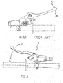
- a device of this type is depicted in Figure 1 .
- EP1325863A1 discloses a master cylinder lever device having a push rod with a ball head having oppositely extending posts, and a socket insert having a leading ball socket with opposite slots for snap fit receiving the ball head with the posts received in the corresponding slots, wherein the socket insert is received within a keyed orifice in the lever handle.
- the object of the invention is to provide a new and improved control lever device.
- Figure 1 illustrates a control lever device of the prior art
- Figure 2 is a perspective view of an embodiment of the device according to the invention.
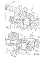
- Figures 3 and 4 are sectional views of several details of the device from figure 2 ;
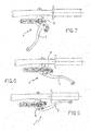
- FIGS 5, 6 and 7 illustrate the control lever device in three operating positions
- a control lever device is generally designated with 1.
- the device 1 comprises a support structure 2 with means for connecting the device 1 to a handlebar, for example one or more tightening portions 3 provided with suitable holes 4 that are optionally threaded to house clamping screws.
- a cylinder-piston group for example in the form of a cylinder-piston unit that is manufactured separate from the support structure and subsequently connected thereto, or, as shown in the figures, a cylindrical housing 5 being directly made in the support structure 2 that slidingly houses a piston 6.
- a lever 7 is pivotally connected to the support structure 2 along an angular actuation stroke A extending from an angular rest position R of lever 7 in a first direction of rotation and along an angular collapse stroke C extending from said angular rest portion R in a second direction of rotation opposite the first direction of rotation.
- a transmission portion 8 is associated with the device 1 such as to transmit the movement of lever 7 along the angular actuation stroke A to the cylinder-piston unit, particularly to piston 6.
- the transmission portion 8 is arranged relative to lever 7 such that, when the lever 7 is in the angular collapse stroke C, it is separated from the transmission portion 8 meaning that a force applied on lever 7 cannot be transmitted therefrom by direct contact to the transmission portion 8 or, in other words, a force applied on the lever is directly transmitted and, preferably exclusively, to the support structure 2, thus bypassing the transmission portion 8.
- lever 7 When the lever 7 is in the angular actuation stroke A, it abuts against the transmission portion 8 to allow the transmission of the movement of lever 7 to the cylinder-piston unit, particularly to piston 6, in order to actuate either the brake or clutch.
- the transmission portion 8 is provided as an elongated push rod having a preferably circular cross-sectional shape.
- the push rod has a first end 9 that is held into permanent contact to a seat 2 of piston 6 and a second end 10 that is free and suitable to abut against a suitable seat 11 of the lever 7, when the latter is in the angular actuation stroke A.
- connection of the transmission portion 8 to the support structure 2 is provided in a position away from the position of a pin 26 providing the pivotal connection of lever 7 to the support structure 2. Due to the distance between the pin 26 and the transmission portion 8, any stroke or impact on the lever 7 is counteracted only by the support structure 2 (which is usually very solid) without damaging the transmission portion 8.
- the transmission portion 8 comprises, in an intermediate area between the first end 9 and the second end 10, a connecting portion 13 for the connection of the transmission portion 8 to a gasket 14 being provided for protecting the cylinder-piston unit from the external environment.
- the gasket 14 has the shape of a cup with a smooth or bellows side wall 15.
- the circumferential edge 16 of the open side of gasket 14 is inserted in a suitable seat 17 being formed all around an opening 18 through which the transmission portion 8 extends from the outside into the seat 12 of piston 6.
- the connecting portion 13 of the transmission portion 8 is a circumferential groove formed by two parallel circumferential flanges 19, suitable to house a preferably circular edge 20 of an opening formed in a bottom wall 21 of the gasket 14 opposite the open side thereof.
- the gasket 14 is made of an elastomeric or elastic material and is formed and positioned such as to hold the transmission portion 8, i.e. the push rod, elastically in a preset position at least when lever 7 is in the angular collapse stroke.
- adjusting means suitable to adjust the relative position of the seat 11 and the lever 7, such as to be able of adjusting the angular rest position of the lever 7 according to the user's requirements.
- the adjusting means comprise an adjusting screw 22 that is screwed in a suitable threaded hole of the lever 7, the seat 11 being formed at an end of the adjusting screw 22 facing the transmission portion 8.
- the seat 11 is funnel-shaped such as to facilitate the proper positioning and mutual engagement of the seat 11 of lever 7 with the second end 10 of the transmission portion 8, when the lever 7 shifts from the angular collapse stroke C to the rest position R.
- a helical torsion spring 23 is arranged in an annular seat 24 obtained in the lever 7 about a hole 25 to house the pin 26.
- a first end 23a of the helical spring 23 rests against a wall of a recess 23b of the annular seat 24 of lever 7 and a second end 23c of helical spring 23 rests against a suitable seat 23d of the support structure 2.
- the helical spring 23 pushes the lever 7 elastically in the direction of the angular actuation stroke A and a second spring (not shown in the figures) pushes the piston 6 in an end-of-stroke position thereof corresponding to the rest position of lever 7, thereby counteracting the thrust of the helical spring 23.
- the force produced by the second spring is greater than the force of the first spring, in order to ensure that, when the lever 7 has not been actuated, the piston 6 remains in its end-of-stroke position and the lever 7 remains in its rest position R.
- the helical spring 23 pushes the lever 7 elastically against the transmission portion 8, the funnel shape of the seat 11 of lever 7 ensuring the perfect mutual positioning of the lever 7 relative to the transmission portion 8.
- the lever 7 Upon an accident or a simple fall of the motorcycle causing the lever 7 to move In the direction opposite to that provided for actuating the brake or clutch, the lever 7 enters its angular collapse stroke C and, at the same time, separates the seat 11 from the transmission portion 8.
- the transmission portion 8 is elastically held in position due to the gasket 14 of the cylinder-piston unit. The movements and impacts, particularly those transversal to the plane in which the lever 7 can be rotated are transmitted from the lever 7 only to the support structure 2 without acting on the transmission portion 8, which is then unloaded.
- the helical spring 23 takes the lever 7 again to the rest position R and the seat 11 of the lever engages the free end of the transmission portion 8, which is elastically positioned due to the elastic gasket 14 of the cylinder-piston unit.
- the device according to the invention has a number of advantages.
- the device has a simple structure with a few pieces, the transmission portion does not require complex mechanical processing and strict size tolerances.
Landscapes
- Engineering & Computer Science (AREA)
- Mechanical Engineering (AREA)
- Physics & Mathematics (AREA)
- Fluid Mechanics (AREA)
- Steering Devices For Bicycles And Motorcycles (AREA)
- Mechanical Control Devices (AREA)
- Switches With Compound Operations (AREA)
Claims (11)
- Dispositif de levier de commande (1) pour véhicules, comprenant :une structure de support (2) avec des moyens (3, 4) pour connecter le dispositif (1) à un guidon ;une unité cylindre-piston (5, 6) connectée à la structure de support (2) ;un levier connecté à pivotement à la structure de support (2) suivant une course d'actionnement angulaire (A) s'étendant depuis une position angulaire de repos (R) du levier (7) dans une première direction de rotation et suivant une course de repliement angulaire (C) s'étendant depuis ladite position angulaire de repos (R) dans une seconde direction de rotation, opposée à la première direction ;une partie de transmission (8) associée au dispositif (1) de façon à transmettre le mouvement du levier (7) le long de la course d'actionnement angulaire (A) à l'unité cylindre-piston (5, 6) ;dans lequel la partie de transmission (8) est agencée par rapport au levier (7) de telle manière que, quand le levier (7) est dans la course de repliement angulaire (C), le levier (7) est séparé de la partie de transmission (8),dans lequel la partie de transmission (8) comprend une première extrémité (9) étant en contact permanent avec un piston (6) de l'unité cylindre-piston (5, 6) et une seconde extrémité (10) libre convenant pour venir en butée contre un siège (11) du levier (7),quand ce dernier est dans la course d'actionnement angulaire (A),dans lequel des moyens de guidage (11) sont fournis pour faciliter le positionnement mutuel correct du siège (11) du levier (7) et de la seconde extrémité (10) de la partie de transmission (8), quand le levier (7) est déplacé de la course de repliement angulaire (C) vers la position angulaire de repos (R), dans lequel lesdits moyens de guidage (11) comprennent le siège (11) en forme d'entonnoir.
- Dispositif (1) selon la revendication 1, dans lequel quand le levier (7) est dans la course de repliement angulaire (C), une force appliquée sur le levier (7) ne peut pas être transmise de ce dernier au moyen d'un contact direct avec la partie de transmission (8).
- Dispositif (1) selon la revendication 1 ou 2, dans lequel quand le levier (7) est dans la course de repliement angulaire (C), il est séparé de la partie de transmission (8) de telle manière qu'une force appliquée sur le levier (7) est transmise à la structure de support (2) évitant ainsi la partie de transmission (8).
- Dispositif (1) selon l'une quelconque des revendications précédentes, dans lequel quand le levier (7) est dans la course d'actionnement angulaire (A), il repose contre la partie de transmission (8) pour permettre ladite transmission du mouvement du levier (7) à l'unité cylindre-piston (5, 6).
- Dispositif (1) selon l'une quelconque des revendications précédentes, dans lequel la partie de transmission (8) est connectée à la structure de support (2) dans une position à distance de la partie de connexion (11) de la structure de support (2) au levier (7).
- Dispositif (1) selon l'une quelconque des revendications précédentes, dans lequel des moyens élastiques (14) sont prévus qui conviennent pour maintenir la partie de transmission (8) élastiquement dans une position préétablie quand le levier (7) est dans la course de repliement angulaire (C).
- Dispositif (1) selon la revendication précédente, dans lequel lesdits moyens élastiques sont fournis par une garniture élastique (14) de l'unité cylindre-piston (5, 6).
- Dispositif (1) selon l'une quelconque des revendications précédentes, comprenant des moyens élastique (23) agissant entre la structure de support (2) et le levier (7) de façon à maintenir le levier (7) élastiquement dans la position de repos (R).
- Dispositif (1) selon la revendication précédente, dans lequel lesdits moyens élastiques comprennent un premier ressort (23) agissant directement entre la structure de support (2) et le levier (7) poussant le levier (7) dans la direction de la course d'actionnement angulaire (A) et un second ressort poussant le piston (6) de l'unité cylindre-piston (5, 6) dans une position de fin de course correspondant à la position de repos (R) du levier (7), allant ainsi à l'encontre de la poussée du premier ressort (23).
- Dispositif (1) selon l'une quelconque des revendications précédentes, comprenant en outre des moyens d'ajustement (22) convenant pour ajuster la position relative entre le siège (11) du levier (7) et le levier (7) lui-même, de façon à pouvoir régler la position angulaire de repos (R) du levier (7).
- Dispositif (1) selon les revendications précédentes, dans lequel lesdits moyens de réglage (22) comprennent une vis de réglage (22) vissée dans un trou fileté convenable du levier (7), dans lequel ledit siège (11) est formé à une extrémité de la vis de réglage (22).
Applications Claiming Priority (1)
| Application Number | Priority Date | Filing Date | Title |
|---|---|---|---|
| PCT/IT2004/000740 WO2006070417A1 (fr) | 2004-12-30 | 2004-12-30 | Dispositif de levier de commande repliable |
Publications (3)
| Publication Number | Publication Date |
|---|---|
| EP1831068A1 EP1831068A1 (fr) | 2007-09-12 |
| EP1831068B1 EP1831068B1 (fr) | 2010-10-27 |
| EP1831068B2 true EP1831068B2 (fr) | 2019-01-02 |
Family
ID=34960187
Family Applications (1)
| Application Number | Title | Priority Date | Filing Date |
|---|---|---|---|
| EP04806903.3A Expired - Lifetime EP1831068B2 (fr) | 2004-12-30 | 2004-12-30 | Dispositif de levier de commande repliable |
Country Status (5)
| Country | Link |
|---|---|
| US (1) | US8276477B2 (fr) |
| EP (1) | EP1831068B2 (fr) |
| AT (1) | ATE486000T1 (fr) |
| DE (1) | DE602004029830D1 (fr) |
| WO (1) | WO2006070417A1 (fr) |
Families Citing this family (14)
| Publication number | Priority date | Publication date | Assignee | Title |
|---|---|---|---|---|
| US8393244B2 (en) * | 2007-08-06 | 2013-03-12 | Shimano Inc. | Bicycle operating device |
| DE102007040364B4 (de) | 2007-08-24 | 2022-02-24 | Gustav Magenwirth Gmbh & Co. Kg | Betätigungsarmatur |
| JP5288298B2 (ja) * | 2008-12-24 | 2013-09-11 | フレニ ブレンボ エス.ピー.エー. | 折り畳み自在なレバーを備えた作動装置 |
| US8943924B2 (en) * | 2010-11-24 | 2015-02-03 | Hb Performance Systems, Inc. | System and method for an adjustable lever assembly |
| DE102013200824A1 (de) | 2013-01-18 | 2014-07-24 | Gustav Magenwirth Gmbh & Co. Kg | Geberarmatur für eine hydraulische Scheibenbremse |
| US9062752B2 (en) | 2013-04-23 | 2015-06-23 | Fca Us Llc | Park release apparatus for a transmission |
| DE102014111641A1 (de) * | 2014-08-14 | 2016-02-18 | Gustav Magenwirth Gmbh & Co. Kg | Handbetätigte Gebereinheit |
| US9932086B2 (en) * | 2014-11-13 | 2018-04-03 | Robert L. Barnett | Motorcycle front brake master cylinder assembly |
| US10625813B2 (en) | 2014-11-13 | 2020-04-21 | Robert L. Barnett | Motorcycle front brake master cylinder assembly |
| US10137957B2 (en) * | 2015-08-06 | 2018-11-27 | Shimano Inc. | Bicycle operating device |
| USD774429S1 (en) * | 2015-12-03 | 2016-12-20 | Helio Ascari | Bicycle brake lever |
| IT201600111274A1 (it) * | 2016-11-04 | 2018-05-04 | Freni Brembo Spa | Dispositivo a leva |
| IT201700107310A1 (it) * | 2017-09-26 | 2019-03-26 | Freni Brembo Spa | Dispositivo attuatore per impianto idraulico di attuazione di freno/frizione di un motociclo, con regolazione indipendente della distanza e dell’interasse della leva di azionamento |
| EP4454960A1 (fr) * | 2023-04-27 | 2024-10-30 | Brembo S.p.A. | Ensemble levier, dispositif de levier |
Citations (3)
| Publication number | Priority date | Publication date | Assignee | Title |
|---|---|---|---|---|
| US4635442A (en) † | 1984-08-29 | 1987-01-13 | Automotive Products Plc | Hydraulic master cylinder assembly |
| US20010003927A1 (en) † | 1999-12-16 | 2001-06-21 | Nissin Kogyo Co., Ltd. | Control lever equipment for bar handle vehicle |
| EP1325863A1 (fr) † | 2001-12-28 | 2003-07-09 | Avid, LLC | Maítre cylindre pour frein à disque ayant une ajustabilité à la volée |
Family Cites Families (6)
| Publication number | Priority date | Publication date | Assignee | Title |
|---|---|---|---|---|
| US3368421A (en) * | 1965-06-11 | 1968-02-13 | Eaton Yale & Towne | Break-away shift lever |
| US4730509A (en) | 1985-04-24 | 1988-03-15 | Hornady Robert S | Breakaway control levers |
| US6393936B1 (en) | 1999-07-15 | 2002-05-28 | Robert L. Barnett | Collapsible control lever |
| EP1160152B1 (fr) * | 2000-06-02 | 2005-12-07 | Freni Brembo S.p.A. | Dispositif pour ajuster la position du levier de fonctionnement d'un vérin hydraulique |
| US6739133B2 (en) | 2001-12-03 | 2004-05-25 | Robert L. Barnett | Motorcycle control lever |
| US6892603B2 (en) | 2002-05-03 | 2005-05-17 | Robert L. Barnett | Rotatable control lever mount |
-
2004
- 2004-12-30 DE DE602004029830T patent/DE602004029830D1/de not_active Expired - Lifetime
- 2004-12-30 AT AT04806903T patent/ATE486000T1/de not_active IP Right Cessation
- 2004-12-30 EP EP04806903.3A patent/EP1831068B2/fr not_active Expired - Lifetime
- 2004-12-30 US US11/722,819 patent/US8276477B2/en active Active
- 2004-12-30 WO PCT/IT2004/000740 patent/WO2006070417A1/fr not_active Ceased
Patent Citations (3)
| Publication number | Priority date | Publication date | Assignee | Title |
|---|---|---|---|---|
| US4635442A (en) † | 1984-08-29 | 1987-01-13 | Automotive Products Plc | Hydraulic master cylinder assembly |
| US20010003927A1 (en) † | 1999-12-16 | 2001-06-21 | Nissin Kogyo Co., Ltd. | Control lever equipment for bar handle vehicle |
| EP1325863A1 (fr) † | 2001-12-28 | 2003-07-09 | Avid, LLC | Maítre cylindre pour frein à disque ayant une ajustabilité à la volée |
Also Published As
| Publication number | Publication date |
|---|---|
| EP1831068A1 (fr) | 2007-09-12 |
| WO2006070417A1 (fr) | 2006-07-06 |
| US8276477B2 (en) | 2012-10-02 |
| US20070283774A1 (en) | 2007-12-13 |
| EP1831068B1 (fr) | 2010-10-27 |
| DE602004029830D1 (de) | 2010-12-09 |
| ATE486000T1 (de) | 2010-11-15 |
Similar Documents
| Publication | Publication Date | Title |
|---|---|---|
| EP1831068B2 (fr) | Dispositif de levier de commande repliable | |
| US9751591B2 (en) | Hydraulic dual control device for bicycle | |
| USRE44839E1 (en) | Collapsible control lever | |
| EP2281740B1 (fr) | Appareil de contrôle de frein et son levier de commande | |
| EP2891598B1 (fr) | Dispositif de réglage de tige d'assise par commande de câble | |
| EP1964764B1 (fr) | Ajustement en hauteur pour ensemble de levier assemblé sur un guidon | |
| EP2281741B1 (fr) | Appareil de contrôle de frein hydraulique | |
| EP2367716B1 (fr) | Dispositif d'actionnement avec levier pliable | |
| EP3018049B1 (fr) | Dispositif de commande de frein hydraulique pour un guidon de bicyclette | |
| EP2463190A1 (fr) | Actionneur pour changement de vitesse de bicyclette et écrou correspondant | |
| EP2666705B1 (fr) | Système de régulation de vitesse de motocyclette | |
| US10711808B2 (en) | Bar-end type bicycle hydraulic operating device | |
| CN104554611A (zh) | 自行车操作设备 | |
| TWI617485B (zh) | 自行車輪緣制動器 | |
| US8336308B2 (en) | Lever device for operating a hydraulic actuator, particularly for motorcycles | |
| US10676150B2 (en) | Integrated drive for bicycle handlebars | |
| CN107878659B (zh) | 自行车液压操作装置 | |
| EP3317175B1 (fr) | Ensemble levier de commande à distance | |
| US8322248B2 (en) | Setting screw for a control lever device | |
| EP2148805B1 (fr) | Dispositif de levier de commande pliable | |
| CN108698667A (zh) | 用于车辆的可调节压缩悬架套件 | |
| US20070199400A1 (en) | Actuation lever system with breakaway element and simple assembly |
Legal Events
| Date | Code | Title | Description |
|---|---|---|---|
| PUAI | Public reference made under article 153(3) epc to a published international application that has entered the european phase |
Free format text: ORIGINAL CODE: 0009012 |
|
| 17P | Request for examination filed |
Effective date: 20070615 |
|
| AK | Designated contracting states |
Kind code of ref document: A1 Designated state(s): AT BE BG CH CY CZ DE DK EE ES FI FR GB GR HU IE IS IT LI LT LU MC NL PL PT RO SE SI SK TR |
|
| DAX | Request for extension of the european patent (deleted) | ||
| 17Q | First examination report despatched |
Effective date: 20090429 |
|
| GRAP | Despatch of communication of intention to grant a patent |
Free format text: ORIGINAL CODE: EPIDOSNIGR1 |
|
| GRAS | Grant fee paid |
Free format text: ORIGINAL CODE: EPIDOSNIGR3 |
|
| RIN1 | Information on inventor provided before grant (corrected) |
Inventor name: PEZOTTA, GIANANGELO Inventor name: LAVEZZI, ROBERTO Inventor name: COLOMBO, MARCELLO |
|
| GRAA | (expected) grant |
Free format text: ORIGINAL CODE: 0009210 |
|
| AK | Designated contracting states |
Kind code of ref document: B1 Designated state(s): AT BE BG CH CY CZ DE DK EE ES FI FR GB GR HU IE IS IT LI LT LU MC NL PL PT RO SE SI SK TR |
|
| REG | Reference to a national code |
Ref country code: GB Ref legal event code: FG4D |
|
| REG | Reference to a national code |
Ref country code: CH Ref legal event code: EP |
|
| REG | Reference to a national code |
Ref country code: IE Ref legal event code: FG4D |
|
| REF | Corresponds to: |
Ref document number: 602004029830 Country of ref document: DE Date of ref document: 20101209 Kind code of ref document: P |
|
| REG | Reference to a national code |
Ref country code: NL Ref legal event code: VDEP Effective date: 20101027 |
|
| LTIE | Lt: invalidation of european patent or patent extension |
Effective date: 20101027 |
|
| PG25 | Lapsed in a contracting state [announced via postgrant information from national office to epo] |
Ref country code: LT Free format text: LAPSE BECAUSE OF FAILURE TO SUBMIT A TRANSLATION OF THE DESCRIPTION OR TO PAY THE FEE WITHIN THE PRESCRIBED TIME-LIMIT Effective date: 20101027 |
|
| PG25 | Lapsed in a contracting state [announced via postgrant information from national office to epo] |
Ref country code: PT Free format text: LAPSE BECAUSE OF FAILURE TO SUBMIT A TRANSLATION OF THE DESCRIPTION OR TO PAY THE FEE WITHIN THE PRESCRIBED TIME-LIMIT Effective date: 20110228 Ref country code: IS Free format text: LAPSE BECAUSE OF FAILURE TO SUBMIT A TRANSLATION OF THE DESCRIPTION OR TO PAY THE FEE WITHIN THE PRESCRIBED TIME-LIMIT Effective date: 20110227 Ref country code: NL Free format text: LAPSE BECAUSE OF FAILURE TO SUBMIT A TRANSLATION OF THE DESCRIPTION OR TO PAY THE FEE WITHIN THE PRESCRIBED TIME-LIMIT Effective date: 20101027 Ref country code: AT Free format text: LAPSE BECAUSE OF FAILURE TO SUBMIT A TRANSLATION OF THE DESCRIPTION OR TO PAY THE FEE WITHIN THE PRESCRIBED TIME-LIMIT Effective date: 20101027 Ref country code: FI Free format text: LAPSE BECAUSE OF FAILURE TO SUBMIT A TRANSLATION OF THE DESCRIPTION OR TO PAY THE FEE WITHIN THE PRESCRIBED TIME-LIMIT Effective date: 20101027 Ref country code: SE Free format text: LAPSE BECAUSE OF FAILURE TO SUBMIT A TRANSLATION OF THE DESCRIPTION OR TO PAY THE FEE WITHIN THE PRESCRIBED TIME-LIMIT Effective date: 20101027 Ref country code: SI Free format text: LAPSE BECAUSE OF FAILURE TO SUBMIT A TRANSLATION OF THE DESCRIPTION OR TO PAY THE FEE WITHIN THE PRESCRIBED TIME-LIMIT Effective date: 20101027 Ref country code: BG Free format text: LAPSE BECAUSE OF FAILURE TO SUBMIT A TRANSLATION OF THE DESCRIPTION OR TO PAY THE FEE WITHIN THE PRESCRIBED TIME-LIMIT Effective date: 20110127 |
|
| PG25 | Lapsed in a contracting state [announced via postgrant information from national office to epo] |
Ref country code: GR Free format text: LAPSE BECAUSE OF FAILURE TO SUBMIT A TRANSLATION OF THE DESCRIPTION OR TO PAY THE FEE WITHIN THE PRESCRIBED TIME-LIMIT Effective date: 20110128 Ref country code: BE Free format text: LAPSE BECAUSE OF FAILURE TO SUBMIT A TRANSLATION OF THE DESCRIPTION OR TO PAY THE FEE WITHIN THE PRESCRIBED TIME-LIMIT Effective date: 20101027 |
|
| PG25 | Lapsed in a contracting state [announced via postgrant information from national office to epo] |
Ref country code: EE Free format text: LAPSE BECAUSE OF FAILURE TO SUBMIT A TRANSLATION OF THE DESCRIPTION OR TO PAY THE FEE WITHIN THE PRESCRIBED TIME-LIMIT Effective date: 20101027 Ref country code: CZ Free format text: LAPSE BECAUSE OF FAILURE TO SUBMIT A TRANSLATION OF THE DESCRIPTION OR TO PAY THE FEE WITHIN THE PRESCRIBED TIME-LIMIT Effective date: 20101027 Ref country code: ES Free format text: LAPSE BECAUSE OF FAILURE TO SUBMIT A TRANSLATION OF THE DESCRIPTION OR TO PAY THE FEE WITHIN THE PRESCRIBED TIME-LIMIT Effective date: 20110207 Ref country code: MC Free format text: LAPSE BECAUSE OF NON-PAYMENT OF DUE FEES Effective date: 20101231 |
|
| REG | Reference to a national code |
Ref country code: CH Ref legal event code: PL |
|
| PLBI | Opposition filed |
Free format text: ORIGINAL CODE: 0009260 |
|
| PG25 | Lapsed in a contracting state [announced via postgrant information from national office to epo] |
Ref country code: SK Free format text: LAPSE BECAUSE OF FAILURE TO SUBMIT A TRANSLATION OF THE DESCRIPTION OR TO PAY THE FEE WITHIN THE PRESCRIBED TIME-LIMIT Effective date: 20101027 Ref country code: RO Free format text: LAPSE BECAUSE OF FAILURE TO SUBMIT A TRANSLATION OF THE DESCRIPTION OR TO PAY THE FEE WITHIN THE PRESCRIBED TIME-LIMIT Effective date: 20101027 Ref country code: DK Free format text: LAPSE BECAUSE OF FAILURE TO SUBMIT A TRANSLATION OF THE DESCRIPTION OR TO PAY THE FEE WITHIN THE PRESCRIBED TIME-LIMIT Effective date: 20101027 Ref country code: PL Free format text: LAPSE BECAUSE OF FAILURE TO SUBMIT A TRANSLATION OF THE DESCRIPTION OR TO PAY THE FEE WITHIN THE PRESCRIBED TIME-LIMIT Effective date: 20101027 |
|
| PLAX | Notice of opposition and request to file observation + time limit sent |
Free format text: ORIGINAL CODE: EPIDOSNOBS2 |
|
| 26 | Opposition filed |
Opponent name: GUSTAV MAGENWIRTH GMBH & CO. KG Effective date: 20110727 |
|
| REG | Reference to a national code |
Ref country code: FR Ref legal event code: ST Effective date: 20110831 |
|
| REG | Reference to a national code |
Ref country code: DE Ref legal event code: R026 Ref document number: 602004029830 Country of ref document: DE Effective date: 20110727 |
|
| PG25 | Lapsed in a contracting state [announced via postgrant information from national office to epo] |
Ref country code: CH Free format text: LAPSE BECAUSE OF NON-PAYMENT OF DUE FEES Effective date: 20101231 Ref country code: IE Free format text: LAPSE BECAUSE OF NON-PAYMENT OF DUE FEES Effective date: 20101230 Ref country code: LI Free format text: LAPSE BECAUSE OF NON-PAYMENT OF DUE FEES Effective date: 20101231 Ref country code: FR Free format text: LAPSE BECAUSE OF NON-PAYMENT OF DUE FEES Effective date: 20110103 |
|
| PLAF | Information modified related to communication of a notice of opposition and request to file observations + time limit |
Free format text: ORIGINAL CODE: EPIDOSCOBS2 |
|
| PLBB | Reply of patent proprietor to notice(s) of opposition received |
Free format text: ORIGINAL CODE: EPIDOSNOBS3 |
|
| PG25 | Lapsed in a contracting state [announced via postgrant information from national office to epo] |
Ref country code: CY Free format text: LAPSE BECAUSE OF FAILURE TO SUBMIT A TRANSLATION OF THE DESCRIPTION OR TO PAY THE FEE WITHIN THE PRESCRIBED TIME-LIMIT Effective date: 20101027 |
|
| PG25 | Lapsed in a contracting state [announced via postgrant information from national office to epo] |
Ref country code: LU Free format text: LAPSE BECAUSE OF NON-PAYMENT OF DUE FEES Effective date: 20101230 Ref country code: HU Free format text: LAPSE BECAUSE OF FAILURE TO SUBMIT A TRANSLATION OF THE DESCRIPTION OR TO PAY THE FEE WITHIN THE PRESCRIBED TIME-LIMIT Effective date: 20110428 |
|
| PG25 | Lapsed in a contracting state [announced via postgrant information from national office to epo] |
Ref country code: TR Free format text: LAPSE BECAUSE OF FAILURE TO SUBMIT A TRANSLATION OF THE DESCRIPTION OR TO PAY THE FEE WITHIN THE PRESCRIBED TIME-LIMIT Effective date: 20101027 |
|
| PLAB | Opposition data, opponent's data or that of the opponent's representative modified |
Free format text: ORIGINAL CODE: 0009299OPPO |
|
| R26 | Opposition filed (corrected) |
Opponent name: GUSTAV MAGENWIRTH GMBH & CO. KG Effective date: 20110727 |
|
| APAH | Appeal reference modified |
Free format text: ORIGINAL CODE: EPIDOSCREFNO |
|
| APBM | Appeal reference recorded |
Free format text: ORIGINAL CODE: EPIDOSNREFNO |
|
| APBP | Date of receipt of notice of appeal recorded |
Free format text: ORIGINAL CODE: EPIDOSNNOA2O |
|
| APBQ | Date of receipt of statement of grounds of appeal recorded |
Free format text: ORIGINAL CODE: EPIDOSNNOA3O |
|
| PGFP | Annual fee paid to national office [announced via postgrant information from national office to epo] |
Ref country code: GB Payment date: 20161222 Year of fee payment: 13 |
|
| PGFP | Annual fee paid to national office [announced via postgrant information from national office to epo] |
Ref country code: DE Payment date: 20170228 Year of fee payment: 13 |
|
| PLAB | Opposition data, opponent's data or that of the opponent's representative modified |
Free format text: ORIGINAL CODE: 0009299OPPO |
|
| R26 | Opposition filed (corrected) |
Opponent name: GUSTAV MAGENWIRTH GMBH & CO. KG Effective date: 20110727 |
|
| APBU | Appeal procedure closed |
Free format text: ORIGINAL CODE: EPIDOSNNOA9O |
|
| REG | Reference to a national code |
Ref country code: DE Ref legal event code: R119 Ref document number: 602004029830 Country of ref document: DE |
|
| GBPC | Gb: european patent ceased through non-payment of renewal fee |
Effective date: 20171230 |
|
| PG25 | Lapsed in a contracting state [announced via postgrant information from national office to epo] |
Ref country code: DE Free format text: LAPSE BECAUSE OF NON-PAYMENT OF DUE FEES Effective date: 20180703 |
|
| PG25 | Lapsed in a contracting state [announced via postgrant information from national office to epo] |
Ref country code: GB Free format text: LAPSE BECAUSE OF NON-PAYMENT OF DUE FEES Effective date: 20171230 |
|
| PUAH | Patent maintained in amended form |
Free format text: ORIGINAL CODE: 0009272 |
|
| STAA | Information on the status of an ep patent application or granted ep patent |
Free format text: STATUS: PATENT MAINTAINED AS AMENDED |
|
| 27A | Patent maintained in amended form |
Effective date: 20190102 |
|
| AK | Designated contracting states |
Kind code of ref document: B2 Designated state(s): AT BE BG CH CY CZ DE DK EE ES FI FR GB GR HU IE IS IT LI LT LU MC NL PL PT RO SE SI SK TR |
|
| REG | Reference to a national code |
Ref country code: DE Ref legal event code: R102 Ref document number: 602004029830 Country of ref document: DE |
|
| P01 | Opt-out of the competence of the unified patent court (upc) registered |
Effective date: 20230526 |
|
| PGFP | Annual fee paid to national office [announced via postgrant information from national office to epo] |
Ref country code: IT Payment date: 20231006 Year of fee payment: 20 |