EP2281740B1 - Appareil de contrôle de frein et son levier de commande - Google Patents
Appareil de contrôle de frein et son levier de commande Download PDFInfo
- Publication number
- EP2281740B1 EP2281740B1 EP20100000049 EP10000049A EP2281740B1 EP 2281740 B1 EP2281740 B1 EP 2281740B1 EP 20100000049 EP20100000049 EP 20100000049 EP 10000049 A EP10000049 A EP 10000049A EP 2281740 B1 EP2281740 B1 EP 2281740B1
- Authority
- EP
- European Patent Office
- Prior art keywords
- mounting
- control lever
- section
- lever
- mounting portion
- Prior art date
- Legal status (The legal status is an assumption and is not a legal conclusion. Google has not performed a legal analysis and makes no representation as to the accuracy of the status listed.)
- Active
Links
Images



Classifications
-
- B—PERFORMING OPERATIONS; TRANSPORTING
- B60—VEHICLES IN GENERAL
- B60T—VEHICLE BRAKE CONTROL SYSTEMS OR PARTS THEREOF; BRAKE CONTROL SYSTEMS OR PARTS THEREOF, IN GENERAL; ARRANGEMENT OF BRAKING ELEMENTS ON VEHICLES IN GENERAL; PORTABLE DEVICES FOR PREVENTING UNWANTED MOVEMENT OF VEHICLES; VEHICLE MODIFICATIONS TO FACILITATE COOLING OF BRAKES
- B60T11/00—Transmitting braking action from initiating means to ultimate brake actuator without power assistance or drive or where such assistance or drive is irrelevant
- B60T11/10—Transmitting braking action from initiating means to ultimate brake actuator without power assistance or drive or where such assistance or drive is irrelevant transmitting by fluid means, e.g. hydraulic
- B60T11/16—Master control, e.g. master cylinders
- B60T11/165—Single master cylinders for pressurised systems
-
- B—PERFORMING OPERATIONS; TRANSPORTING
- B60—VEHICLES IN GENERAL
- B60T—VEHICLE BRAKE CONTROL SYSTEMS OR PARTS THEREOF; BRAKE CONTROL SYSTEMS OR PARTS THEREOF, IN GENERAL; ARRANGEMENT OF BRAKING ELEMENTS ON VEHICLES IN GENERAL; PORTABLE DEVICES FOR PREVENTING UNWANTED MOVEMENT OF VEHICLES; VEHICLE MODIFICATIONS TO FACILITATE COOLING OF BRAKES
- B60T11/00—Transmitting braking action from initiating means to ultimate brake actuator without power assistance or drive or where such assistance or drive is irrelevant
- B60T11/10—Transmitting braking action from initiating means to ultimate brake actuator without power assistance or drive or where such assistance or drive is irrelevant transmitting by fluid means, e.g. hydraulic
- B60T11/16—Master control, e.g. master cylinders
- B60T11/18—Connection thereof to initiating means
-
- B—PERFORMING OPERATIONS; TRANSPORTING
- B60—VEHICLES IN GENERAL
- B60T—VEHICLE BRAKE CONTROL SYSTEMS OR PARTS THEREOF; BRAKE CONTROL SYSTEMS OR PARTS THEREOF, IN GENERAL; ARRANGEMENT OF BRAKING ELEMENTS ON VEHICLES IN GENERAL; PORTABLE DEVICES FOR PREVENTING UNWANTED MOVEMENT OF VEHICLES; VEHICLE MODIFICATIONS TO FACILITATE COOLING OF BRAKES
- B60T7/00—Brake-action initiating means
- B60T7/02—Brake-action initiating means for personal initiation
- B60T7/08—Brake-action initiating means for personal initiation hand actuated
- B60T7/10—Disposition of hand control
- B60T7/102—Disposition of hand control by means of a tilting lever
-
- B—PERFORMING OPERATIONS; TRANSPORTING
- B62—LAND VEHICLES FOR TRAVELLING OTHERWISE THAN ON RAILS
- B62K—CYCLES; CYCLE FRAMES; CYCLE STEERING DEVICES; RIDER-OPERATED TERMINAL CONTROLS SPECIALLY ADAPTED FOR CYCLES; CYCLE AXLE SUSPENSIONS; CYCLE SIDECARS, FORECARS, OR THE LIKE
- B62K23/00—Rider-operated controls specially adapted for cycles, i.e. means for initiating control operations, e.g. levers, grips
- B62K23/02—Rider-operated controls specially adapted for cycles, i.e. means for initiating control operations, e.g. levers, grips hand actuated
- B62K23/06—Levers
-
- Y—GENERAL TAGGING OF NEW TECHNOLOGICAL DEVELOPMENTS; GENERAL TAGGING OF CROSS-SECTIONAL TECHNOLOGIES SPANNING OVER SEVERAL SECTIONS OF THE IPC; TECHNICAL SUBJECTS COVERED BY FORMER USPC CROSS-REFERENCE ART COLLECTIONS [XRACs] AND DIGESTS
- Y10—TECHNICAL SUBJECTS COVERED BY FORMER USPC
- Y10T—TECHNICAL SUBJECTS COVERED BY FORMER US CLASSIFICATION
- Y10T74/00—Machine element or mechanism
- Y10T74/20—Control lever and linkage systems
- Y10T74/20207—Multiple controlling elements for single controlled element
- Y10T74/20256—Steering and controls assemblies
- Y10T74/20268—Reciprocating control elements
- Y10T74/2028—Handle bar type
Definitions
- the present invention relates to a control lever, and more particularly to a control lever with a portion embedded in a bar opening of a bicycle handlebar.
- Hydraulic brake systems have been utilized on bicycles to provide powerful, safe, and stable braking effects.
- Such hydraulic brake systems can include a brake lever mounted on a handlebar of a bicycle, a disc brake mounted beside a wheel of the bicycle, and a hydraulic tube interconnecting the brake lever and the disc brake. Due to the size and shape of the components of conventional hydraulic brake levers, such brake levers are typically mounted on the handlebar using a bracket affixed to an outer circumference of the handlebar. However, such a mounting configuration may not be ideal, since many of the components of the hydraulic brake lever may be exposed and therefore susceptible to damage or environmental factors.
- a control lever that has a body portion having a first section configured to fit within an interior of a bar opening, said first section being configured to house at least a portion of a control mechanism, said first section having a inclined surface on an outer surface thereof.
- This known control lever has a mounting portion, configured to move axially within the interior of the bar opening. At least one mounting screw is configured to connect said mounting portion to said body portion. Furthermore, a lever portion is connected to said body portion and configured to actuate the control mechanism. In the known control leaver at least one mounting screw is configured to move said mounting portion axially within the interior of the bar opening so as to squeeze the mounting portion between the inclined surface and the inner surface of the bar opening.
- An embodiment of the present invention advantageously provides a control lever comprising a body portion, a mounting portion, at least one mounting screw, and a lever portion.
- the body portion has a first section configured to fit within an interior of a bar opening, where the first section is configured to house at least a portion of a control mechanism, and where the first section has an inclined surface on an outer surface thereof.
- the mounting portion is configured to slide on the inclined surface.
- the at least one mounting screw is configured to connect the mounting portion to the body portion.
- the lever portion is connected to the body portion and is configured to actuate the control mechanism.
- the at least one mounting screw is configured to slide the mounting portion along the inclined surface so as to push the mounting portion and a side of the first section against an inner surface of the bar opening in order to mount the body portion to the bar opening.
- the mounting portion moves in an expanding direction from said first section when said mounting portion slides along said inclined surface.
- a further embodiment of the present invention advantageously provides a hydraulic brake control apparatus comprising a control lever including a hydraulic brake pressure cylinder arranged as part of a hydraulic brake control mechanism.
- the control lever includes: a body portion having a first section configured to fit within an interior of a bar opening, where the first section houses the hydraulic brake pressure cylinder, and where the first section has an inclined surface on an outer surface thereof; a mounting portion configured to slide on the inclined surface; at least one mounting screw configured to connect the mounting portion to the body portion; and a lever portion connected to the body portion and configured to actuate the control mechanism.
- the at least one mounting screw is configured to slide the mounting portion along the inclined surface so as to push the mounting portion and a side of the first section against an inner surface of the bar opening in order to mount the body portion to the bar opening.
- the mounting portion moves in an expanding direction from said first section when said mounting portion slides along said inclined surface.
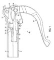
- FIG. 1 is a front, elevational view of a hydraulic brake control apparatus including a control lever 100, which is mounted to a handlebar 10, according to an embodiment of the present invention.
- the handlebar 10 is shown as being transparent so that components of the hydraulic brake control apparatus that are received within the handlebar 10 can be seen therethrough.
- FIG. 1 depicts a handlebar 10 that is a tubular member having a hollow interior with an inner surface 12 and an open terminal end 14.
- the handlebar 10 can be, for example, for a bicycle or other vehicle that utilizes such a hydraulic brake control apparatus.
- the tubular member can have a circular cross-sectional shape, or other non-circular (e.g., oval, square, etc.) cross-sectional shape if desired.
- the control lever 100 of the hydraulic brake control apparatus is configured to be mounted to the end 14 of the handlebar 10, with at least a portion of the components of the hydraulic brake apparatus received within the hollow interior of the handlebar 10.
- the hydraulic brake control apparatus includes a hydraulic brake control mechanism including a hydraulic brake pressure cylinder or master cylinder 131, the operation of which is discussed in greater detail with respect to FIG. 3 .
- the hydraulic brake pressure cylinder 131 and various components thereof are housed within a section 130 of a body portion 110 of the control lever 100, and are actuated by a lever portion 160 of the control lever 100.
- control lever 100 includes a body portion 110 having an exterior section 112 that is configured to be outside of the tubular member or bar opening when mounted to the handlebar 10, and the interior section 130 that is configured to fit within the interior of a tubular member or bar opening.
- the exterior section 112 of the body portion 110 includes a lip portion 114 that abuts against the end 14 of the handlebar 10 when the control lever 100 is mounted to the handlebar 10.
- the exterior section 112 includes a hole 116 that extends therethrough that receives an axle 170 that is used to pivotally mount the lever portion 160 to the body portion 110.
- the exterior section 112 includes an opening 118 that houses a valve that can be used to inject hydraulic fluid into the hydraulic pressure cylinder 131 and/or bleed air out of the hydraulic pressure cylinder 131.
- the exterior section 112 also includes a recessed portion 120 that receives an upper end 162 of the lever portion 160 for pivotal actuation thereof about the axle 170.
- the interior section 130 of the body portion 110 houses the hydraulic brake pressure cylinder 131.
- the interior section 130 includes a mounting surface 132 on a lower side thereof, and an inclined surface 134 on an outer upper surface thereof.
- the mounting surface 132 is configured to press against the inner surface 12 of the handlebar 10 when the control lever 100 is mounted on the end 14 of the handlebar 10.
- the inclined surface 134 is inclined to slant upwards and away from the mounting surface 132 as the inclined surface 134 approaches the exterior section 112.
- the control lever 110 includes a mounting portion or mounting block 140 that is connected to the body portion 110 by mounting screws or bolts 150 and 152.
- the mounting portion 140 has threaded holes 142 and 144 that are threadably engaged to the threaded mounting screws 150 and 152, respectively.
- the mounting portion 140 has a lower curved surface 146 that is configured to slidably receive or abut the inclined surface 134.
- the mounting portion 140 has an upper surface 148 that is configured to press against the inner surface 12 of the handlebar 10 when the control lever 100 is mounted on the end 14 of the handlebar 10 and the mounting screws are rotated to draw the mounting portion 140 towards the exterior section 112.
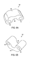
- the mounting portion has a generally U-shaped configuration; however, is mounted in an inverted manner (as in FIG. 6A ) in FIG. 1 .
- the mounting screws 150 and 152 are inserted through apertures 122 and 124, respectively, in the exterior section 112 of the body portion 110.
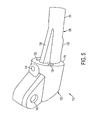
- the mounting screws can be inserted via the recessed portion 120, as can be seen in FIG. 2 .
- the apertures 122 and 124 are configured to receive the mounting screws 150 and 152 such that the mounting screws can move in a direction perpendicular to a longitudinal axis of the mounting screws when the mounting portion 140 slides along the inclined surface 134.
- the mounting screws 150 and 152 can be mounted such that they pivot about the head thereof, and/or slide upward or downward.
- the pivoting/sliding of the mounting screws allows the elevation of the screws or the terminal ends of the screws to change upward or downward as the mounting portion 140 slides to the right or the left, respectively, as shown by the arrows in FIG. 3 . Also, as the mounting portion 140 slides to the right, as shown in FIG. 3 , the mounting portion 140 moves towards the inner surface 12 of the handlebar 10 in an expanding direction.
- the mounting screws 150 and 152 are generally provided at a different angle from the hydraulic pressure cylinder 131 and the inclined surface 134 when connected to the mounting portion 140.
- the apertures 122 and 124 can provide for such pivoting of the mounting screws 150 and 152, for example, by providing the apertures with a generally truncated cone-shaped cross-section (not shown) when taken along a plane parallel to the cross-sectional plane of FIG. 3 , where a narrower end of the truncated cone is on a right side as viewed in the same orientation of FIG. 3 and a wider end of the truncated cone is on a left side.
- the heads of the mounting screws 150 and 152 will retain the screws 150 and 152 in connection with the exterior section 112 of the body portion 110 by the narrower end of the truncated cone, and the wider end will allow the terminal ends of the mounting screws to move upward or downward as the mounting portion 140 slides along the inclined surface 134.
- the apertures 122 and 124 can provide for movement/pivoting of the mounting screws 150 and 152 by providing the apertures 122 and 124 with a slot shape, for example, a shape having two semi-circular ends connected by two straight sides.
- the threads on the mounting screws 150 and 152 which are threadably engaged to the threaded holes 142 and 144 on the mounting portion 140, will act to slide the mounting portion 145 along inclined surface 134. Therefore, in order to tightly mount the control lever 100 to the handlebar 10, the control lever 100 is positioned as shown, for example, in FIG. 3 , and then the mounting screws 150 and 152 are rotated in a direction that pulls the mounting portion 140 in a rightward direction towards the exterior section 112 until the upper surface 148 of the mounting portion 140 contacts the inner surface 12 of the handlebar 10.
- the upper surface 148 of the mounting portion 140 due to interaction between the mounting portion 140 and the inclined surface 134, will push/press against the inner surface 12 of the handlebar and the lower mounting surface 132 will push/press against an opposite side of the inner surface 12 of the handlebar 10 in order to firmly mount the control lever 10 to the handlebar 10.
- a feature for example, an expanded portion or pin or other feature at the terminal end of the mounting screws, that prevents the mounting portion from becoming disengaged from the mounting screws.
- control lever can include a configuration in which one mounting screw is utilized.
- the mounting portion and/or the inclined surface is/are preferably configured to prevent the ability of the mounting portion to rotate within the interior of the handlebar as the mounting screw is rotated.
- Further alternative embodiments can be provided in which a channel or groove extends along the upper surface of the inclined surface, and the mounting portion is received within the groove or has a projection that extends within the groove in order to guide the mounting portion along the inclined surface.
- the control lever 100 further includes the lever portion 160.
- the lever portion 160 has an upper end 162 and a lower end 164.
- the upper end 162 of the lever portion 160 is pivotally mounted to the exterior section 112 by the axle 170 mounted within hole 116 that extends through the exterior section 112 on both sides of the recessed portion 120.
- the lower end 164 of the lever portion 160 can be used as a handle by the user to actuate the control mechanism of the hydraulic brake control apparatus by pulling the lower end 164 towards the handlebar 10.
- the hydraulic brake control apparatus includes a hydraulic brake control mechanism including the hydraulic brake pressure cylinder 131.
- the hydraulic brake pressure cylinder 131 and various components thereof are housed within a section 130 of a body portion 110 of the control lever 100, and are actuated by a lever portion 160 of the control lever 100.
- the lever portion 160 is pivotally attached to a push-rod 190 by a pin 180.
- the pin 180 is fixed to a first end 192 of the push-rod 190, and the pin 180 is configured to pivot with respect to the lever portion 160.
- a second end 194 of the push-rod 190 is pivotally fixed to a piston 196 that is slidably provided within a chamber 200 of the hydraulic brake pressure cylinder 131. Hydraulic fluid is provided within the chamber 200.
- port 202 will be connected to a hydraulic tube that will carry the hydraulic fluid to a disc brake mounted beside a wheel of the bicycle in order to actuate the hydraulic brake and apply a braking force to the wheel of the bicycle.
- Embodiments of the present invention advantageously provide a control lever that includes components thereof that are received within an interior of a handlebar, while still allowing the control lever to be mounted to an inner surface of the handlebar. By mounting such components within an interior of the handlebar, such components can be protected from damage caused by contact with objects and by environmental factors. Such embodiments of a control lever can also provide a very aesthetically pleasing appearance by hiding the components within the hollow handlebar, thereby giving the control lever a very sleek appearance.
- control lever as being utilized as part of a hydraulic brake control apparatus
- other embodiments can include the control lever as part of a brake control apparatus that utilize other types of braking systems and configurations.
- control lever as part of other control apparatuses, such as for a derailleur system.
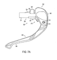
- FIGS. 7A and 7B are schematic views of a brake control apparatus including a control lever 300, according to an embodiment of the present invention.
- the brake control apparatus of FIGS. 7A and 7B is a cable braking system (not shown), such as a caliper, disc, or drum brake system. While specific reference will be made thereto, it is to be appreciated that the control apparatus also finds application in other vehicles, such as tricycles, motorcycles, etc., as well as in other control lever actuated systems, such as gear shift systems.
- the control lever 300 is configured to be mounted to a handlebar that is a tubular member having a hollow interior with an inner surface and an open terminal end.
- the brake control apparatus includes a cable brake control mechanism including a cable brake cylinder 331.
- the cable brake cylinder 331 and various components thereof are housed within a section 330 of a body portion 310 of the control lever 300, and are actuated by a lever portion 360 of the control lever 300.
- the configuration of the cable braking components of the control lever and the operation thereof can be provided, for example, as shown and described in U.S. Pub. No. 2009/0114057 A1 , which is incorporated by reference herein in its entirety.
- the control lever 300 includes a body portion 310 having an exterior section 312 that is configured to be outside of the tubular member or bar opening when mounted to the handlebar, and the interior section 330 that is configured to fit within the interior of a tubular member or bar opening.
- the exterior section 312 of the body portion 310 includes a lip portion 314 that abuts against the end of the handlebar when the control lever 300 is mounted to the handlebar.
- the exterior section 312 includes a hole 316 that extends therethrough that receives an axle 370 that is used to pivotally mount the lever portion 360 to the body portion 310.
- the exterior section 312 also includes a recessed portion that receives an upper end 362 of the lever portion 360 for pivotal actuation thereof about the axle 370.
- the interior section 330 of the body portion 310 houses the brake cylinder 331.
- the interior section 330 includes a mounting surface 332 on a lower side thereof, and an inclined surface 334 on an outer upper surface thereof.
- the mounting surface 332 is configured to press against the inner surface of the handlebar when the control lever 300 is mounted on the end of the handlebar.
- the inclined surface 334 is inclined to slant upwards and away from the mounting surface 332 as the inclined surface 334 approaches the exterior section 312.
- the control lever 310 includes a mounting portion or mounting block 340 that is connected to the body portion 310 by mounting screws or bolts 350 in the same manner as in the previous embodiment (see FIG. 4 ).
- the mounting portion 340 has threaded holes that are threadably engaged to the threaded mounting screws in the same manner as in the previous embodiment and that operate in the same manner as in the previous embodiment.
- the mounting portion 240 has an upper surface that is configured to press against the inner surface of the handlebar when the control lever 300 is mounted on the end of the handlebar and the mounting screws are rotated to draw the mounting portion 340 towards the exterior section 312.
- the lever portion 360 has an upper end 362 and a lower end 364.
- the upper end 362 of the lever portion 360 is pivotally mounted to the exterior section 312 by the axle 370 mounted within hole 316 that extends through the exterior section 312 on both sides of the recessed portion.
- the lower end 364 of the lever portion 360 can be used as a handle by the user to actuate the control mechanism of the cable brake control apparatus by pulling the lower end 364 towards the handlebar.
- the lever portion 360 pivots about axle 370 and a slot 361 on a terminal end of the upper end 362 pulls a cable 400 in a rightward direction in FIG.
Landscapes
- Engineering & Computer Science (AREA)
- Mechanical Engineering (AREA)
- Transportation (AREA)
- Transmission Of Braking Force In Braking Systems (AREA)
- Mechanical Control Devices (AREA)
- Steering Devices For Bicycles And Motorcycles (AREA)
- Braking Systems And Boosters (AREA)
- Braking Elements And Transmission Devices (AREA)
Claims (9)
- Un levier de commande (100) comprenant :un corps (110) possédant une première section (130) configurée pour tenir à l'intérieur d'une ouverture du guidon, ladite première section (130) étant configurée pour contenir au moins une partie d'un mécanisme de commande, ladite première section (130) possédant une surface inclinée (134) sur une surface extérieure de celle-ci ;une partie de montage (140) configurée pour coulisser sur ladite surface inclinée (134) ;au moins une vis de montage (150, 152) configurée pour se raccorder à ladite partie de montage (140) dudit corps (110) ; etune partie à levier (160) raccordée à ladite partie du corps (110) et configurée pour actionner le mécanisme de commande,
dans lequel ladite partie de montage (140) se déplace dans une direction par expansion par rapport à ladite première section (130) lorsque ladite partie de montage (140) coulisse le long de ladite surface inclinée (134),
caractérisé par le fait qu'au moins une vis de montage (150, 152) susmentionnée est configurée pour coulisser ladite partie de montage (140) le long de ladite surface inclinée (134), de façon à pousser ladite partie de montage (140) et un côté de ladite première section (130) contre une surface intérieure de l'ouverture du guidon, de façon à monter ladite partie du corps (110) sur l'ouverture du guidon. - Le levier de commande (100) selon la revendication 1 ou 2, dans lequel ladite première section (130) comprend un cylindre de pression pour frein hydraulique (131).
- Le levier de commande (100) selon la revendication 1 ou 2, dans lequel ladite partie du corps (110) comprend une deuxième section (112) configurée pour être montée à l'extérieur de l'intérieur de l'ouverture du guidon.
- Le levier de commande (100) selon la revendication 3, dans lequel au moins une vis de montage (150, 152) susmentionnée se déplace dans une ouverture (122, 124) dans ladite deuxième section (112), dans laquelle au moins une vis de montage (150, 152) susmentionnée s'engage par vissage dans un orifice fileté (142, 144) sur ladite partie de montage (140).
- Le levier de commande (100) selon la revendication 4, dans lequel ladite ouverture (122, 124) dans ladite deuxième section (112) est configurée pour recevoir au moins une vis de montage (150, 152) susmentionnée, de sorte qu'au moins une des vis de montage (150, 152) susmentionnée se déplace dans une direction substantiellement perpendiculaire à l'axe longitudinal d'au moins une vis de montage (150, 152) susmentionnée lorsque ladite partie de montage (140) coulisse le long de ladite surface inclinée (134).
- Le levier de commande (100) selon une quelconque des revendications 1 à 5, comprenant une première vis de montage (150) et une deuxième vis de montage (152), et dans lequel ladite première vis de montage (150) et ladite deuxième vis de montage (152) sont chacune engagées par vissage dans un orifice fileté (142, 144) sur ladite partie de montage (140).
- Le levier de commande (100) selon une quelconque des revendications 1 à 6, dans lequel ladite partie de montage (140) présente une section en coupe ayant une forme générale en « U ».
- Un dispositif de commande pour frein hydraulique, comprenant :un levier de commande conforme à une quelconque des revendications 2 à 7, lorsqu'elle est tributaire de la revendication 2, dans lequel le cylindre de pression pour frein hydraulique (131) fait partie du mécanisme de commande du frein hydraulique.
- Un guidon (10) composé d'un élément tubulaire, dont l'intérieur creux abrite une surface interne (12) et un terminal ouvert (14), caractérisé par un levier de commande (100) selon une quelconque des revendications 1 à 7, dans le cadre duquel la première section (130) du levier de commande (100) est monté dans l'intérieur à travers le terminal ouvert (14) ou caractérisé par un dispositif de commande pour frein hydraulique selon la revendication 8, la première section (130) du levier de commande (100) du dispositif de commande pour frein hydraulique étant montée à l'intérieur, à travers le bout du terminal ouvert (14).
Applications Claiming Priority (1)
| Application Number | Priority Date | Filing Date | Title |
|---|---|---|---|
| US12/535,704 US8863912B2 (en) | 2009-08-05 | 2009-08-05 | Brake control apparatus and control lever therefor |
Publications (3)
| Publication Number | Publication Date |
|---|---|
| EP2281740A2 EP2281740A2 (fr) | 2011-02-09 |
| EP2281740A3 EP2281740A3 (fr) | 2011-09-21 |
| EP2281740B1 true EP2281740B1 (fr) | 2015-03-18 |
Family
ID=41728172
Family Applications (1)
| Application Number | Title | Priority Date | Filing Date |
|---|---|---|---|
| EP20100000049 Active EP2281740B1 (fr) | 2009-08-05 | 2010-01-06 | Appareil de contrôle de frein et son levier de commande |
Country Status (3)
| Country | Link |
|---|---|
| US (1) | US8863912B2 (fr) |
| EP (1) | EP2281740B1 (fr) |
| TW (1) | TWI476129B (fr) |
Families Citing this family (18)
| Publication number | Priority date | Publication date | Assignee | Title |
|---|---|---|---|---|
| EP2699469A2 (fr) * | 2011-04-19 | 2014-02-26 | Gustav Magenwirth GmbH & Co. KG | Transmetteur pour élément d'actionnement hydraulique |
| DE102011078480A1 (de) * | 2011-06-30 | 2013-01-03 | Gustav Magenwirth Gmbh & Co. Kg | Geber für ein hydraulisches Betätigungselement |
| US8714322B2 (en) | 2012-01-16 | 2014-05-06 | Sram, Llc | Hydraulic brake mechanism |
| US9268354B1 (en) | 2012-04-19 | 2016-02-23 | Evolve Technologies, Llc | Lever assemblies and methods |
| US9630677B2 (en) * | 2012-06-15 | 2017-04-25 | Sram, Llc | Brake control apparatus |
| CN103716847B (zh) * | 2012-09-28 | 2019-06-14 | 北京三星通信技术研究有限公司 | 一种通过网关建立x2的方法 |
| JP3182207U (ja) * | 2012-12-26 | 2013-03-14 | 株式会社シマノ | 自転車用制御装置 |
| ITMI20130950A1 (it) * | 2013-06-10 | 2014-12-11 | Campagnolo Srl | Complesso di manubrio di bicicletta con comandi oleoidraulici integrati |
| US9896150B2 (en) * | 2015-01-30 | 2018-02-20 | Shimano Inc. | Bicycle operating device |
| US10189531B2 (en) * | 2015-05-08 | 2019-01-29 | Shimano Inc. | Bicycle operating device |
| USD774429S1 (en) * | 2015-12-03 | 2016-12-20 | Helio Ascari | Bicycle brake lever |
| JP2018001883A (ja) * | 2016-06-28 | 2018-01-11 | 株式会社シマノ | 自転車用バーエンド |
| US10384741B2 (en) * | 2016-09-30 | 2019-08-20 | Shimano Inc. | Bicycle hydraulic operating device |
| US10882580B2 (en) * | 2016-11-01 | 2021-01-05 | Shimano Inc. | Bicycle component mounting device |
| US10167041B2 (en) | 2016-11-01 | 2019-01-01 | Shimano Inc. | Bicycle operating device |
| US10583890B2 (en) * | 2017-02-21 | 2020-03-10 | Shimano Inc. | Bar-end device assembly for tube member of bicycle |
| USD844928S1 (en) * | 2017-07-25 | 2019-04-02 | Cambro Manufacturing Company | Dish caddy adjusting lever |
| US10767715B2 (en) * | 2018-10-11 | 2020-09-08 | Bendix Spicer Foundation Brake Llc | Pivotable actuator mounting device |
Family Cites Families (37)
| Publication number | Priority date | Publication date | Assignee | Title |
|---|---|---|---|---|
| GB190403651A (en) | 1904-02-13 | 1904-05-26 | Frederick George Heath | Improvements in Hydraulic Brakes for Cycles and Motor Vehicles |
| GB140267A (en) | 1919-05-20 | 1920-03-25 | Henry Arthur Lamplugh | Improvements in operating devices for bowden wire mechanism |
| US1526681A (en) * | 1924-07-16 | 1925-02-17 | A M A C Ltd | Handlebar-control mechanism for use on motor cycles and the like |
| DE502132C (de) | 1928-10-24 | 1930-07-10 | Benjamin Hans Seibold | Lagerbock fuer den Bedienungshebel von in den Lenkstangen von Motorraedern gefuehrten Bowdenzuegen |
| FR663073A (fr) | 1928-10-24 | 1929-08-16 | Perfectionnement aux poignées de commande de freins et analogues pour cycles et motocycles | |
| US2271273A (en) * | 1940-05-18 | 1942-01-27 | Cleveland Welding Co | Hydraulic brake control for bicycles |
| FR884159A (fr) | 1942-07-13 | 1943-08-04 | Perfectionnements aux commandes de câbles sous gaine utilisées sur les bicyclettes, motocyclettes et autres véhicules | |
| FR59965E (fr) * | 1950-01-23 | 1954-09-22 | Dispositif de commande de freins à patins pour bicyclettes, motocyclettes ou véhicules analogues | |
| JPS526115Y2 (fr) | 1972-04-04 | 1977-02-08 | ||
| JPS5655108Y2 (fr) * | 1977-07-12 | 1981-12-22 | ||
| US4462267A (en) * | 1980-03-01 | 1984-07-31 | Shimano Industrial Company, Limited | Handlebar for a bicycle |
| US4624597A (en) * | 1984-08-23 | 1986-11-25 | Reliance Electric Company | Flanged bushing mounting adaptor |
| JPH0248315Y2 (fr) | 1985-05-09 | 1990-12-18 | ||
| IT1209673B (it) | 1985-11-19 | 1989-08-30 | Sarano Di Santa Lucia Di Piave | Dispositivo di azionamento di un freno per bicicletta, in particolare per bicicletta da corsa. |
| JPH0356473Y2 (fr) | 1987-05-29 | 1991-12-18 | ||
| DE3724427A1 (de) | 1987-07-23 | 1989-02-02 | Detlef Schroeder | Schnell loesbare handhebelbefestigung am lenkerbuegel |
| JPH0180590U (fr) | 1987-11-19 | 1989-05-30 | ||
| US5197349A (en) * | 1991-04-11 | 1993-03-30 | Hsin Lung Accessories Co., Ltd. | Expander nut structure for a handlebar stem |
| US5201242A (en) * | 1992-04-24 | 1993-04-13 | Chi Yi C | Coupling for supporting a front fork in the head tube of a bicycle |
| US5285696A (en) * | 1992-09-21 | 1994-02-15 | Answer Products, Inc. | Bar end assembly attachable to the steerer bars of bicycle handlebar systems |
| WO1995007836A1 (fr) | 1993-09-14 | 1995-03-23 | Anton Kyzlink | Dispositif de commande de frein pour bicyclette |
| US5540457A (en) * | 1994-08-31 | 1996-07-30 | Rocky Mountain Bicycle Company Ltd. | Steering assembly with external bearing pre-load adjustment |
| US5647684A (en) * | 1995-05-16 | 1997-07-15 | Chen; Chia-Ching | Two-step and toothless bicycle head shaft bowl set |
| DE29603807U1 (de) | 1996-03-01 | 1996-05-09 | Arnold, Franc, 56068 Koblenz | Betätigungsvorrichtung für eine Fahrrad-Felgenbremse |
| US6502675B1 (en) * | 2000-01-11 | 2003-01-07 | Frank G. Andrus | Integrated handlebar and master cylinder having piston and hydraulic line coaxially aligned with major central axis of handlebar |
| TWI238796B (en) * | 2003-01-06 | 2005-09-01 | Int Bicycle Products Corp | Handlebar grip for transport vehicles |
| JP2005088642A (ja) * | 2003-09-12 | 2005-04-07 | Kawasaki Heavy Ind Ltd | 車両の油圧発生装置 |
| US7350436B2 (en) | 2004-03-29 | 2008-04-01 | Shimano, Inc. | Electrical bicycle shift control device |
| US7240772B2 (en) * | 2005-05-27 | 2007-07-10 | Tektro Technology Corporation | Embedding typed handbrake operating device |
| US7565848B2 (en) * | 2006-01-13 | 2009-07-28 | Shimano Inc. | Bicycle control device |
| US8056439B2 (en) * | 2007-11-06 | 2011-11-15 | Shimano Inc. | Device to mount control lever to bicycle |
| US7562932B2 (en) * | 2007-11-12 | 2009-07-21 | Tien Hsin Indistries Co., Ltd. | Seat support structure of a bicycle |
| US20090152063A1 (en) * | 2007-12-13 | 2009-06-18 | Szu-Fang Tsai | Pumping device for a hydraulic brake of a bicycle |
| US20090152061A1 (en) * | 2007-12-13 | 2009-06-18 | Szu-Fang Tsai | Adjustable pumping device for a hydraulic brake device of a bicycle |
| TWM349884U (en) | 2008-09-10 | 2009-02-01 | Shieny Co Ltd | Insertion-type handbrake grip structure |
| US9403512B2 (en) * | 2009-08-05 | 2016-08-02 | Shimano Inc. | Hydraulic brake control apparatus |
| EP2699469A2 (fr) * | 2011-04-19 | 2014-02-26 | Gustav Magenwirth GmbH & Co. KG | Transmetteur pour élément d'actionnement hydraulique |
-
2009
- 2009-08-05 US US12/535,704 patent/US8863912B2/en active Active
- 2009-12-15 TW TW098142963A patent/TWI476129B/zh active
-
2010
- 2010-01-06 EP EP20100000049 patent/EP2281740B1/fr active Active
Also Published As
| Publication number | Publication date |
|---|---|
| EP2281740A2 (fr) | 2011-02-09 |
| US20110031079A1 (en) | 2011-02-10 |
| TW201105544A (en) | 2011-02-16 |
| TWI476129B (zh) | 2015-03-11 |
| US8863912B2 (en) | 2014-10-21 |
| EP2281740A3 (fr) | 2011-09-21 |
Similar Documents
| Publication | Publication Date | Title |
|---|---|---|
| EP2281740B1 (fr) | Appareil de contrôle de frein et son levier de commande | |
| EP2281741B1 (fr) | Appareil de contrôle de frein hydraulique | |
| US9630677B2 (en) | Brake control apparatus | |
| US10737744B2 (en) | Bicycle operating device | |
| US9550544B2 (en) | Bicycle handlebar clamp assembly | |
| US10583890B2 (en) | Bar-end device assembly for tube member of bicycle | |
| US10711808B2 (en) | Bar-end type bicycle hydraulic operating device | |
| US20130277162A1 (en) | Bicycle hydraulic operating device | |
| US9321501B1 (en) | Bicycle control device | |
| US10183724B2 (en) | Bicycle hydraulic operating system | |
| CN101337569A (zh) | 具有将缆线致动器转换为液压致动器的转换器的多位制动杆系统 | |
| US10189540B2 (en) | Bicycle hydraulic operating device | |
| US10384741B2 (en) | Bicycle hydraulic operating device | |
| US9963193B2 (en) | Cable positioning structure for hydraulic brake of bicycle | |
| US20160090149A1 (en) | Cable positioning structure for hydraulic brake of bicycle |
Legal Events
| Date | Code | Title | Description |
|---|---|---|---|
| PUAI | Public reference made under article 153(3) epc to a published international application that has entered the european phase |
Free format text: ORIGINAL CODE: 0009012 |
|
| AK | Designated contracting states |
Kind code of ref document: A2 Designated state(s): AT BE BG CH CY CZ DE DK EE ES FI FR GB GR HR HU IE IS IT LI LT LU LV MC MK MT NL NO PL PT RO SE SI SK SM TR |
|
| AX | Request for extension of the european patent |
Extension state: AL BA RS |
|
| PUAL | Search report despatched |
Free format text: ORIGINAL CODE: 0009013 |
|
| AK | Designated contracting states |
Kind code of ref document: A3 Designated state(s): AT BE BG CH CY CZ DE DK EE ES FI FR GB GR HR HU IE IS IT LI LT LU LV MC MK MT NL NO PL PT RO SE SI SK SM TR |
|
| AX | Request for extension of the european patent |
Extension state: AL BA RS |
|
| RIC1 | Information provided on ipc code assigned before grant |
Ipc: B60T 11/18 20060101ALI20110816BHEP Ipc: B60T 11/16 20060101ALI20110816BHEP Ipc: B60T 7/10 20060101ALI20110816BHEP Ipc: B62L 3/02 20060101AFI20110816BHEP Ipc: B62K 23/06 20060101ALI20110816BHEP |
|
| 17P | Request for examination filed |
Effective date: 20120316 |
|
| 17Q | First examination report despatched |
Effective date: 20140205 |
|
| GRAP | Despatch of communication of intention to grant a patent |
Free format text: ORIGINAL CODE: EPIDOSNIGR1 |
|
| INTG | Intention to grant announced |
Effective date: 20140924 |
|
| GRAS | Grant fee paid |
Free format text: ORIGINAL CODE: EPIDOSNIGR3 |
|
| GRAA | (expected) grant |
Free format text: ORIGINAL CODE: 0009210 |
|
| AK | Designated contracting states |
Kind code of ref document: B1 Designated state(s): AT BE BG CH CY CZ DE DK EE ES FI FR GB GR HR HU IE IS IT LI LT LU LV MC MK MT NL NO PL PT RO SE SI SK SM TR |
|
| REG | Reference to a national code |
Ref country code: GB Ref legal event code: FG4D |
|
| REG | Reference to a national code |
Ref country code: CH Ref legal event code: EP |
|
| REG | Reference to a national code |
Ref country code: IE Ref legal event code: FG4D |
|
| REG | Reference to a national code |
Ref country code: AT Ref legal event code: REF Ref document number: 716368 Country of ref document: AT Kind code of ref document: T Effective date: 20150415 |
|
| REG | Reference to a national code |
Ref country code: DE Ref legal event code: R096 Ref document number: 602010023140 Country of ref document: DE Effective date: 20150430 |
|
| REG | Reference to a national code |
Ref country code: NL Ref legal event code: VDEP Effective date: 20150318 |
|
| REG | Reference to a national code |
Ref country code: NL Ref legal event code: VDEP Effective date: 20150318 |
|
| PG25 | Lapsed in a contracting state [announced via postgrant information from national office to epo] |
Ref country code: SE Free format text: LAPSE BECAUSE OF FAILURE TO SUBMIT A TRANSLATION OF THE DESCRIPTION OR TO PAY THE FEE WITHIN THE PRESCRIBED TIME-LIMIT Effective date: 20150318 Ref country code: HR Free format text: LAPSE BECAUSE OF FAILURE TO SUBMIT A TRANSLATION OF THE DESCRIPTION OR TO PAY THE FEE WITHIN THE PRESCRIBED TIME-LIMIT Effective date: 20150318 Ref country code: LT Free format text: LAPSE BECAUSE OF FAILURE TO SUBMIT A TRANSLATION OF THE DESCRIPTION OR TO PAY THE FEE WITHIN THE PRESCRIBED TIME-LIMIT Effective date: 20150318 Ref country code: NO Free format text: LAPSE BECAUSE OF FAILURE TO SUBMIT A TRANSLATION OF THE DESCRIPTION OR TO PAY THE FEE WITHIN THE PRESCRIBED TIME-LIMIT Effective date: 20150618 Ref country code: FI Free format text: LAPSE BECAUSE OF FAILURE TO SUBMIT A TRANSLATION OF THE DESCRIPTION OR TO PAY THE FEE WITHIN THE PRESCRIBED TIME-LIMIT Effective date: 20150318 |
|
| REG | Reference to a national code |
Ref country code: AT Ref legal event code: MK05 Ref document number: 716368 Country of ref document: AT Kind code of ref document: T Effective date: 20150318 |
|
| REG | Reference to a national code |
Ref country code: LT Ref legal event code: MG4D |
|
| PG25 | Lapsed in a contracting state [announced via postgrant information from national office to epo] |
Ref country code: LV Free format text: LAPSE BECAUSE OF FAILURE TO SUBMIT A TRANSLATION OF THE DESCRIPTION OR TO PAY THE FEE WITHIN THE PRESCRIBED TIME-LIMIT Effective date: 20150318 Ref country code: GR Free format text: LAPSE BECAUSE OF FAILURE TO SUBMIT A TRANSLATION OF THE DESCRIPTION OR TO PAY THE FEE WITHIN THE PRESCRIBED TIME-LIMIT Effective date: 20150619 |
|
| PG25 | Lapsed in a contracting state [announced via postgrant information from national office to epo] |
Ref country code: NL Free format text: LAPSE BECAUSE OF FAILURE TO SUBMIT A TRANSLATION OF THE DESCRIPTION OR TO PAY THE FEE WITHIN THE PRESCRIBED TIME-LIMIT Effective date: 20150318 |
|
| PG25 | Lapsed in a contracting state [announced via postgrant information from national office to epo] |
Ref country code: RO Free format text: LAPSE BECAUSE OF FAILURE TO SUBMIT A TRANSLATION OF THE DESCRIPTION OR TO PAY THE FEE WITHIN THE PRESCRIBED TIME-LIMIT Effective date: 20150318 Ref country code: SK Free format text: LAPSE BECAUSE OF FAILURE TO SUBMIT A TRANSLATION OF THE DESCRIPTION OR TO PAY THE FEE WITHIN THE PRESCRIBED TIME-LIMIT Effective date: 20150318 Ref country code: CZ Free format text: LAPSE BECAUSE OF FAILURE TO SUBMIT A TRANSLATION OF THE DESCRIPTION OR TO PAY THE FEE WITHIN THE PRESCRIBED TIME-LIMIT Effective date: 20150318 Ref country code: PT Free format text: LAPSE BECAUSE OF FAILURE TO SUBMIT A TRANSLATION OF THE DESCRIPTION OR TO PAY THE FEE WITHIN THE PRESCRIBED TIME-LIMIT Effective date: 20150720 Ref country code: ES Free format text: LAPSE BECAUSE OF FAILURE TO SUBMIT A TRANSLATION OF THE DESCRIPTION OR TO PAY THE FEE WITHIN THE PRESCRIBED TIME-LIMIT Effective date: 20150318 Ref country code: EE Free format text: LAPSE BECAUSE OF FAILURE TO SUBMIT A TRANSLATION OF THE DESCRIPTION OR TO PAY THE FEE WITHIN THE PRESCRIBED TIME-LIMIT Effective date: 20150318 |
|
| PG25 | Lapsed in a contracting state [announced via postgrant information from national office to epo] |
Ref country code: AT Free format text: LAPSE BECAUSE OF FAILURE TO SUBMIT A TRANSLATION OF THE DESCRIPTION OR TO PAY THE FEE WITHIN THE PRESCRIBED TIME-LIMIT Effective date: 20150318 Ref country code: PL Free format text: LAPSE BECAUSE OF FAILURE TO SUBMIT A TRANSLATION OF THE DESCRIPTION OR TO PAY THE FEE WITHIN THE PRESCRIBED TIME-LIMIT Effective date: 20150318 Ref country code: IS Free format text: LAPSE BECAUSE OF FAILURE TO SUBMIT A TRANSLATION OF THE DESCRIPTION OR TO PAY THE FEE WITHIN THE PRESCRIBED TIME-LIMIT Effective date: 20150718 |
|
| REG | Reference to a national code |
Ref country code: DE Ref legal event code: R097 Ref document number: 602010023140 Country of ref document: DE |
|
| PLBE | No opposition filed within time limit |
Free format text: ORIGINAL CODE: 0009261 |
|
| STAA | Information on the status of an ep patent application or granted ep patent |
Free format text: STATUS: NO OPPOSITION FILED WITHIN TIME LIMIT |
|
| PG25 | Lapsed in a contracting state [announced via postgrant information from national office to epo] |
Ref country code: DK Free format text: LAPSE BECAUSE OF FAILURE TO SUBMIT A TRANSLATION OF THE DESCRIPTION OR TO PAY THE FEE WITHIN THE PRESCRIBED TIME-LIMIT Effective date: 20150318 |
|
| 26N | No opposition filed |
Effective date: 20151221 |
|
| PG25 | Lapsed in a contracting state [announced via postgrant information from national office to epo] |
Ref country code: SI Free format text: LAPSE BECAUSE OF FAILURE TO SUBMIT A TRANSLATION OF THE DESCRIPTION OR TO PAY THE FEE WITHIN THE PRESCRIBED TIME-LIMIT Effective date: 20150318 |
|
| PG25 | Lapsed in a contracting state [announced via postgrant information from national office to epo] |
Ref country code: BE Free format text: LAPSE BECAUSE OF NON-PAYMENT OF DUE FEES Effective date: 20160131 |
|
| PG25 | Lapsed in a contracting state [announced via postgrant information from national office to epo] |
Ref country code: LU Free format text: LAPSE BECAUSE OF FAILURE TO SUBMIT A TRANSLATION OF THE DESCRIPTION OR TO PAY THE FEE WITHIN THE PRESCRIBED TIME-LIMIT Effective date: 20160106 Ref country code: BE Free format text: LAPSE BECAUSE OF FAILURE TO SUBMIT A TRANSLATION OF THE DESCRIPTION OR TO PAY THE FEE WITHIN THE PRESCRIBED TIME-LIMIT Effective date: 20150318 |
|
| REG | Reference to a national code |
Ref country code: CH Ref legal event code: PL |
|
| GBPC | Gb: european patent ceased through non-payment of renewal fee |
Effective date: 20160106 |
|
| PG25 | Lapsed in a contracting state [announced via postgrant information from national office to epo] |
Ref country code: MC Free format text: LAPSE BECAUSE OF FAILURE TO SUBMIT A TRANSLATION OF THE DESCRIPTION OR TO PAY THE FEE WITHIN THE PRESCRIBED TIME-LIMIT Effective date: 20150318 |
|
| REG | Reference to a national code |
Ref country code: FR Ref legal event code: ST Effective date: 20160930 |
|
| PG25 | Lapsed in a contracting state [announced via postgrant information from national office to epo] |
Ref country code: CH Free format text: LAPSE BECAUSE OF NON-PAYMENT OF DUE FEES Effective date: 20160131 Ref country code: GB Free format text: LAPSE BECAUSE OF NON-PAYMENT OF DUE FEES Effective date: 20160106 Ref country code: LI Free format text: LAPSE BECAUSE OF NON-PAYMENT OF DUE FEES Effective date: 20160131 |
|
| REG | Reference to a national code |
Ref country code: IE Ref legal event code: MM4A |
|
| PG25 | Lapsed in a contracting state [announced via postgrant information from national office to epo] |
Ref country code: FR Free format text: LAPSE BECAUSE OF NON-PAYMENT OF DUE FEES Effective date: 20160201 |
|
| PG25 | Lapsed in a contracting state [announced via postgrant information from national office to epo] |
Ref country code: IE Free format text: LAPSE BECAUSE OF NON-PAYMENT OF DUE FEES Effective date: 20160106 |
|
| PGFP | Annual fee paid to national office [announced via postgrant information from national office to epo] |
Ref country code: IT Payment date: 20170123 Year of fee payment: 8 |
|
| PG25 | Lapsed in a contracting state [announced via postgrant information from national office to epo] |
Ref country code: MT Free format text: LAPSE BECAUSE OF FAILURE TO SUBMIT A TRANSLATION OF THE DESCRIPTION OR TO PAY THE FEE WITHIN THE PRESCRIBED TIME-LIMIT Effective date: 20150318 |
|
| PG25 | Lapsed in a contracting state [announced via postgrant information from national office to epo] |
Ref country code: HU Free format text: LAPSE BECAUSE OF FAILURE TO SUBMIT A TRANSLATION OF THE DESCRIPTION OR TO PAY THE FEE WITHIN THE PRESCRIBED TIME-LIMIT; INVALID AB INITIO Effective date: 20100106 Ref country code: CY Free format text: LAPSE BECAUSE OF FAILURE TO SUBMIT A TRANSLATION OF THE DESCRIPTION OR TO PAY THE FEE WITHIN THE PRESCRIBED TIME-LIMIT Effective date: 20150318 Ref country code: SM Free format text: LAPSE BECAUSE OF FAILURE TO SUBMIT A TRANSLATION OF THE DESCRIPTION OR TO PAY THE FEE WITHIN THE PRESCRIBED TIME-LIMIT Effective date: 20150318 |
|
| PG25 | Lapsed in a contracting state [announced via postgrant information from national office to epo] |
Ref country code: MT Free format text: LAPSE BECAUSE OF FAILURE TO SUBMIT A TRANSLATION OF THE DESCRIPTION OR TO PAY THE FEE WITHIN THE PRESCRIBED TIME-LIMIT Effective date: 20160131 Ref country code: TR Free format text: LAPSE BECAUSE OF FAILURE TO SUBMIT A TRANSLATION OF THE DESCRIPTION OR TO PAY THE FEE WITHIN THE PRESCRIBED TIME-LIMIT Effective date: 20150318 Ref country code: MK Free format text: LAPSE BECAUSE OF FAILURE TO SUBMIT A TRANSLATION OF THE DESCRIPTION OR TO PAY THE FEE WITHIN THE PRESCRIBED TIME-LIMIT Effective date: 20150318 |
|
| PG25 | Lapsed in a contracting state [announced via postgrant information from national office to epo] |
Ref country code: BG Free format text: LAPSE BECAUSE OF FAILURE TO SUBMIT A TRANSLATION OF THE DESCRIPTION OR TO PAY THE FEE WITHIN THE PRESCRIBED TIME-LIMIT Effective date: 20150318 |
|
| PG25 | Lapsed in a contracting state [announced via postgrant information from national office to epo] |
Ref country code: IT Free format text: LAPSE BECAUSE OF NON-PAYMENT OF DUE FEES Effective date: 20180106 |
|
| P01 | Opt-out of the competence of the unified patent court (upc) registered |
Effective date: 20230428 |
|
| REG | Reference to a national code |
Ref country code: DE Ref legal event code: R082 Ref document number: 602010023140 Country of ref document: DE Representative=s name: HOFFMANN EITLE PATENT- UND RECHTSANWAELTE PART, DE |
|
| PGFP | Annual fee paid to national office [announced via postgrant information from national office to epo] |
Ref country code: DE Payment date: 20251203 Year of fee payment: 17 |