EP1831082B1 - Zur befestigung in einem flaschenhals ausgeführter flüssigkeitsspender und entsprechende flasche - Google Patents
Zur befestigung in einem flaschenhals ausgeführter flüssigkeitsspender und entsprechende flasche Download PDFInfo
- Publication number
- EP1831082B1 EP1831082B1 EP05802553A EP05802553A EP1831082B1 EP 1831082 B1 EP1831082 B1 EP 1831082B1 EP 05802553 A EP05802553 A EP 05802553A EP 05802553 A EP05802553 A EP 05802553A EP 1831082 B1 EP1831082 B1 EP 1831082B1
- Authority
- EP
- European Patent Office
- Prior art keywords
- insert
- passageway
- dispenser
- bottle
- neck
- Prior art date
- Legal status (The legal status is an assumption and is not a legal conclusion. Google has not performed a legal analysis and makes no representation as to the accuracy of the status listed.)
- Expired - Lifetime
Links
Images


Classifications
-
- B—PERFORMING OPERATIONS; TRANSPORTING
- B65—CONVEYING; PACKING; STORING; HANDLING THIN OR FILAMENTARY MATERIAL
- B65D—CONTAINERS FOR STORAGE OR TRANSPORT OF ARTICLES OR MATERIALS, e.g. BAGS, BARRELS, BOTTLES, BOXES, CANS, CARTONS, CRATES, DRUMS, JARS, TANKS, HOPPERS, FORWARDING CONTAINERS; ACCESSORIES, CLOSURES, OR FITTINGS THEREFOR; PACKAGING ELEMENTS; PACKAGES
- B65D47/00—Closures with filling and discharging, or with discharging, devices
- B65D47/04—Closures with discharging devices other than pumps
- B65D47/06—Closures with discharging devices other than pumps with pouring spouts or tubes; with discharge nozzles or passages
- B65D47/061—Closures with discharging devices other than pumps with pouring spouts or tubes; with discharge nozzles or passages with telescopic, retractable or reversible spouts, tubes or nozzles
-
- B—PERFORMING OPERATIONS; TRANSPORTING
- B65—CONVEYING; PACKING; STORING; HANDLING THIN OR FILAMENTARY MATERIAL
- B65D—CONTAINERS FOR STORAGE OR TRANSPORT OF ARTICLES OR MATERIALS, e.g. BAGS, BARRELS, BOTTLES, BOXES, CANS, CARTONS, CRATES, DRUMS, JARS, TANKS, HOPPERS, FORWARDING CONTAINERS; ACCESSORIES, CLOSURES, OR FITTINGS THEREFOR; PACKAGING ELEMENTS; PACKAGES
- B65D47/00—Closures with filling and discharging, or with discharging, devices
- B65D47/04—Closures with discharging devices other than pumps
- B65D47/32—Closures with discharging devices other than pumps with means for venting
-
- B—PERFORMING OPERATIONS; TRANSPORTING
- B65—CONVEYING; PACKING; STORING; HANDLING THIN OR FILAMENTARY MATERIAL
- B65D—CONTAINERS FOR STORAGE OR TRANSPORT OF ARTICLES OR MATERIALS, e.g. BAGS, BARRELS, BOTTLES, BOXES, CANS, CARTONS, CRATES, DRUMS, JARS, TANKS, HOPPERS, FORWARDING CONTAINERS; ACCESSORIES, CLOSURES, OR FITTINGS THEREFOR; PACKAGING ELEMENTS; PACKAGES
- B65D51/00—Closures not otherwise provided for
- B65D51/18—Arrangements of closures with protective outer cap-like covers or of two or more co-operating closures
-
- B—PERFORMING OPERATIONS; TRANSPORTING
- B65—CONVEYING; PACKING; STORING; HANDLING THIN OR FILAMENTARY MATERIAL
- B65D—CONTAINERS FOR STORAGE OR TRANSPORT OF ARTICLES OR MATERIALS, e.g. BAGS, BARRELS, BOTTLES, BOXES, CANS, CARTONS, CRATES, DRUMS, JARS, TANKS, HOPPERS, FORWARDING CONTAINERS; ACCESSORIES, CLOSURES, OR FITTINGS THEREFOR; PACKAGING ELEMENTS; PACKAGES
- B65D2251/00—Details relating to container closures
- B65D2251/0003—Two or more closures
- B65D2251/0006—Upper closure
- B65D2251/0015—Upper closure of the 41-type
-
- B—PERFORMING OPERATIONS; TRANSPORTING
- B65—CONVEYING; PACKING; STORING; HANDLING THIN OR FILAMENTARY MATERIAL
- B65D—CONTAINERS FOR STORAGE OR TRANSPORT OF ARTICLES OR MATERIALS, e.g. BAGS, BARRELS, BOTTLES, BOXES, CANS, CARTONS, CRATES, DRUMS, JARS, TANKS, HOPPERS, FORWARDING CONTAINERS; ACCESSORIES, CLOSURES, OR FITTINGS THEREFOR; PACKAGING ELEMENTS; PACKAGES
- B65D2251/00—Details relating to container closures
- B65D2251/0003—Two or more closures
- B65D2251/0068—Lower closure
- B65D2251/0087—Lower closure of the 47-type
Definitions
- the present invention relates to a liquid dispenser according to the preamble of claim 1.
- the invention applies in particular to bottles intended to contain liquids, in particular alcohol, or edible oils.
- a known bottle comprises a dispenser of the aforementioned type which allows the distribution by gravity of the liquid contained in this bottle by pivoting the neck downwards.
- the liquid is guided at the outlet of the bottle by the spout of transverse dimensions smaller than those of the neck.
- DE-A-31 43 319 discloses a dispenser according to the preamble of claim 1.
- FR 2,450,756 discloses another dispenser comprising an external air supply duct.
- An object of the invention is therefore to provide a distributor of the aforementioned type, in which the distribution of the liquid is facilitated, especially if the distribution duct is of small size.
- the subject of the invention is a dispenser according to claim 1.
- the dispenser according to the invention may comprise one or more of the features which are the subject of claims 2 to 7.
- the invention further relates to a bottle according to claim 8.
- inferior and “superior” refer to a bottle at rest, placed on a horizontal plane with its neck directed upwards.
- inside and outside refer to the volume defined by the bottle.
- upstream and downstream refer to the direction of circulation of the liquid when dispensed out of the bottle.
- the distributor 13 comprises an insert 15 mounted in force in the neck 11, the insert 15 delimiting a conduit 17 for dispensing the liquid contained in the bottle 12, and a conduit 19 for supplying outside air into the bottle 12.
- the dispenser 13 further comprises a spout 21 deployable from the insert 15 and a cap 23 screwed onto the neck 11 in the configuration shown in the figure 1 .
- the neck 11 is generally tubular in shape extending along a longitudinal axis X-X '. It has a substantially cylindrical inner circumferential surface delimiting a central passage 27 for distributing the liquid, and an outer peripheral surface 29 provided with a threading tap of the plug 23.
- the neck 11 connects the internal volume 30 of the bottle 12 to the outside the bottle 12.
- the insert 15 is totally arranged in the central passage 27. It comprises a central body 31 of axis X-X ', in which are formed a central channel 33 of axis XX' and a secondary channel 35 parallel, shifted transversely by The body 31 further comprises an upstream portion 37, which extends downwardly and delimits a lower portion of the secondary channel 35.
- the body 31 is substantially cylindrical in shape. It has a diameter smaller than the diameter of the central passage 27.
- the body 31 is provided on its outer peripheral surface with annular ribs 39 for attachment to the neck 11, which bear against the inner peripheral surface 25 of the neck 11 and an upper portion 41 of complementary shape to the central passage 27.
- the ribs 39 seal the neck 11 in a sealed manner.
- the height of the upper part 41 taken along the axis X-X ' is greater than the height of the lower ribs 39.
- the body 31 of the insert 15 has a substantially flat outer surface 43 which is flush with the upper edge 45 of the neck 11 and an inner surface 48 located in the passage 27.
- the central channel 33 comprises a lower portion 47 opening into the inner surface 48 and an upper portion 49 which opens into the outer surface 43 outside the neck 11.
- the lower portion 47 has a transverse dimension greater than the maximum transverse dimension of the spout 21.
- the upper part 49 is of substantially conjugate shape with the spout 21.
- the body 31 delimits, between the lower portion 47 and the upper portion 49 of the channel, a peripheral shoulder 51 directed inwardly. This shoulder 51 forms a stop for locking the lower end 53 of the spout 21, as will be described below.
- the secondary channel 35 is for example of cylindrical shape. It has a constant diameter throughout its length. It opens on the one hand into the inner surface 48 at the end of the upstream part 37 and on the other hand into the outer surface 43 of the body 31.
- the secondary channel 35 forms the external air supply duct 19 in the bottle 12.
- the upstream end of the secondary channel 35 opens into the upstream part 37, which protrudes upstream with respect to the part of the body 31 into which the upstream end of the central channel 33 opens.
- the spout 21 is formed by a tube having at its lower end 53 a flared portion radially outwardly, and at its upper end 55, a bead that projects radially inwards.
- An inner lumen 57 connects the ends 53 and 55.
- the spout 21 is slidably mounted along the longitudinal axis XX 'between a retracted position in the insert 15, shown in FIG. figure 1 and an extended position, partially protruding out of the insert 15 shown in the figure 2 .
- the spout 21 is also rotatably mounted about the axis X-X '.
- a lower region 59 of the pouring spout 21 is received in the lower portion 47 of the central channel 33. Furthermore, an upper region 61 of the spout 21 is disposed in abutment against the body 31 in the upper part 49 of the channel 33 and is flush with the outer surface 43 of the body 31.
- the flared portion 53 abuts the shoulder 51.
- the upper region 61 of the spout 21 protrudes out of the insert 15 beyond the outer surface 43 of the body 31, and the lower region 59 is received in the portion upper 49 of the channel 33.
- the plug 23 comprises a lateral wall 71 of complementary shape to the outer peripheral surface 29 of the neck 11, a substantially flat upper wall 73 extending from the upper edge of the wall 71, and a sealing washer 75 provided with a lug 77 for deploying the spout 21, the washer 75 being attached to the lower surface of the wall 73.
- the deployment pin 77 projects into the interior of the bottle 12 and comprises, at its lower end, a part 79 undercut.
- the plug 23 is releasable between a closed configuration of the conduit 17, shown in FIG. figure 1 , and an opening configuration of the conduit 17 shown on the figure 2 .
- the cap 23 is screwed onto the neck 11. Its side wall 71 is engaged on the outer surface 29 and its upper wall 73 covers the upper edge 45 of the neck 11 and the outer surface 43 of the body 31.
- the sealing washer 75 is resting on the outer surface 43 of the body 31 and closes the air supply duct 19.
- the plug 23 thus forms a releasable shutter of the air supply duct 19.
- the cap 23 keeps the spout 21 in its retracted position.
- the lug 77 is engaged in the upper end 55 of the pouring spout 21. Its undercut portion 79 engages with the annular bead at the end 55, which closes the distribution duct 17 in a sealed manner.
- the stopper 23 thus releasably closes the liquid distribution duct 17.
- the cap 23 is completely away from the neck 11 and the spout 21.
- the plug 23 is in its closed configuration.
- the side wall 71 is screwed tightly onto the neck 11, and the washer 75 closes both the liquid distribution duct 17 and the air supply duct 19.
- the cap 23 is first unscrewed, which causes the lug 77 and the spout 21 to rotate about the axis X-X 'in a substantially helical path upwards.
- the cap 23 is pulled up on the figure 1 , away from the neck 11 along the axis X-X '.
- the air supply duct 19 is then released.
- the lug 77 drives the spout 21 to move it from its retracted position to its deployed position in which the flared portion 53 abuts against the shoulder 51.
- the lug 77 is then released from the upper end 55 of the spout 21.
- the liquid distribution duct 17 is then released. Then the bottle 12 is bent to the left on the figure 2 to distribute the liquid by gravity.
- the outside air enters through the air supply duct 19, and maintains the pressure in the interior volume 30 at a value substantially equal to the atmospheric pressure.
- the flow of liquid flowing out of the bottle 12 through the distribution duct 17 is regular, which facilitates its distribution.
- the second distributor 113 represented on the figure 3 differs from the first distributor 13 by the characteristic that the plug 23 is devoid of pin 77 of deployment of the spout 21.
- the outer surface 43 of the body 31 extends horizontally inside the neck 11 and has a central recess 101 in the form of a bowl.
- the central channel 33 and the secondary channel 35 open into the bottom of this recess 101.
- the lower washer 75 of the stopper 23 bears on the upper end 55 of the spout and holds the elastic lip 103 under stress between the rib 106 and the bottom of the recess 101.
- the elastic lip 103 extends outwardly. It brings the upper end 55 of the spout 21 beyond the upper edge 45 of the neck 11, in an intermediate deployed position represented on the figure 3 .
- the third distributor 213 shown on the Figures 4 and 5 differs from the distributor 13 shown on the figure 1 by the following characteristics.
- the insert 15 comprises an outer peripheral ring 201 which has an inner peripheral surface of complementary shape to the outer peripheral surface 29 of the neck 11.
- the ring 201 is screwed onto this surface 29.
- the ring 201 is connected to the body 31 by an annular upper wall 203 which covers the upper edge 45 of the neck 11.
- the ring 201 maintains the body 31 in position in the neck 11.
- the body 31 has a shape complementary to the central passage 27 and seals the passage 27 in a sealed manner.
- the outer surface 43 of the body 31 extends downstream of the upper edge 45 of the neck 11.
- closure cap 23 of the distribution duct covers only the upper end 55 of the pouring spout 21 in its closed configuration, and does not close the air supply duct 19.
- the dispenser 213 further comprises a capsule 205 selectively closing the air supply duct 19, distinct from the plug 23, mounted permanently on the insert 15.
- This capsule 205 comprises a cylindrical side wall 207 of complementary shape to the outer peripheral surface of the screw ring 201, and a top wall 209 of closure having a central orifice 211 through which the spout 21 is engaged.
- the upper wall 209 is internally provided with a pin 212 for closing the air supply duct 19 which projects inwardly from the neck 11.
- the side wall 207 comprises radial openings 215 in the vicinity of the upper wall 209.
- the closure cap 205 is slidably mounted on the ring 201, along the axis X-X ', between a closed position of the air supply duct 19 shown in FIG. figure 4 , and a release position of this conduit 19 shown on the figure 5 .
- a metal spring 216 is interposed between the lower edge 217 of the screw ring 201 and an annular stop 219 which projects towards the axis XX 'from the side wall 207 of the cap 205.
- the spring 216 biases the cap 205 towards its closed position.
- an elastic member integral with the ring 201 or the wall 207 replaces the spring 216.
- the upper wall 209 is disposed away from the outer surface 43 of the body 31, and the closing pin 212 of the air supply duct 19 is clear of the duct 19.
- the openings 215 open into the space defined between the wall 209 and the outer surface 43.
- the cap 23 of the spout is released and the spout 21 is manually deployed.
- the capsule 205 is moved away from the neck 11, against the spring 216 to bring the abutment 219 of the lower edge 217.
- the upper wall 209 of the capsule 205 then deviates from the outer surface 43 of the body 31 and releases the radial openings 215.
- the outside air enters through the radial openings 215, then flows along the gap defined between the upper wall 209 and the outer surface 43.
- the outside air then enters in the bottle via the air supply duct 19.
- the liquid then flows out of the bottle 12 through the distribution duct 17.
- the releasable capsule 205 is released.
- the capsule 205 is returned to its closed position under the effect of the biasing force of the spring 216.
- the distributor 313 represented on the figure 6 differs from that shown on the figure 5 in that the insert 15 has a structure similar to that of the figure 1 , that is to say that it has no peripheral ring 201 for screwing.
- pouring spout 21 is integral with the body 31 and is not retractable in this body 31.
- the closure cap 205 of the air supply duct 19 is mounted directly sliding on the neck 11 .
- the capsule 205 further comprises an elastic lip 301 that protrudes outwardly from the top wall 209 and extends around the central orifice 211.
- the free edge 303 of the lip 301 bears against an outer peripheral shoulder 305 located at the upper end 55 of the spout 21.
- this distributor 313 is moreover analogous to that of the distributor 213 shown in FIG. figure 5 .
- the elastic biasing force of the capsule 205 towards its closed position is generated by the flexion of the elastic lip 301 when the capsule 205 is moved away from the neck 11.
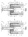
- the distributor 413 represented on the figure 7 differs from the distributor 313 shown on the figure 6 , by the following characteristics.
- the air supply duct 19 comprises, upstream of the outer surface 43 of the body 31, an annular central chamber 401 having a vertical section of transverse dimensions greater than the diameter of the secondary duct 35.
- the upper end of the channel 35 opens into the chamber 401.
- the chamber 401 is connected to the upper surface 43 by an annular channel 402 of vertical section smaller than the vertical section of the chamber 401.
- the body 31 forms, between the annular channel 402 and the upper end of the chamber 401, two peripheral shoulders 403 substantially inclined downstream.
- the closure member 212 comprises a peripheral base 404 which projects downwardly from the upper wall 209.
- the base 404 extends in the annular channel 402 about the axis X-X '.
- the member 212 comprises a lower portion 405 located at the lower end of the base 404 and engaged in the chamber 401.
- the lower portion 405 has upper peripheral edges 407 of respective shapes substantially complementary to the respective shoulders 403 at the end. upper chamber 401.
- the vertical section of the member 212 thus has a shape of arrow directed inwards.
- An elastic flange 409 protrudes from the outer surface 43 of the body 31 and has a free edge 411 bearing on the upper wall 209 of the cap 205.
- the central opening 211 formed in the capsule 205 is of transverse dimension greater than the external diameter of the spout 21.
- the outer surface 43 of the body 31 extends inwardly with respect to the upper edge 45 of the neck 11.
- the plug 23 is integral with the pouring spout 21.
- This stopper 23 is hinged to the spout 21 about a transverse axis YY '.
- the side wall 71 of the cap 23 is substantially complementary in shape to the internal slot 57 of the spout 21.
- the operation of the bottle 413 shown on the figure 7 differs from the operation of the bottle 313 shown on the figure 6 in that, in its closed position, the capsule 205 is biased outwardly by the elastic flange 409. In this closed position, the upper edges 407 of the closure member 212 are respectively disposed in abutment against the respective shoulders 403 of the chamber 401. The air supply duct 19 is thus closed sealingly by the closure member 212.
- the cap 205 is pushed towards the neck 11, against the biasing force of the elastic flange 409.
- the lower portion 405 of the closure member 212 is disposed away from the shoulder 407 of the chamber 401 and the air supply duct 19 is released.
- the air thus flows from the outside towards the inside of the bottle 12, passing through the gap defined between the spout 21 and the opening 211, then in the space delimited between the outer surface 43 of the body. 31 and the upper wall 209 of the capsule 205.
- the active rection for the passage of air between the upper edges 407 and the shoulders 403 is thus high, which is favorable for increasing the flow of liquid through the conduit 17.
- the capsule 205 is released and is returned to its closed position by the elastic flange 409.
- a liquid dispenser comprising an insert intended to be fixed in the neck of a bottle, the dispenser facilitating the dispensing of liquid out of the bottle through to an outside air supply duct formed in the insert away from a liquid distribution duct.
- the dispenser may have a deployable pouring spout and means for activating the deployment of the spout when opening a spout closure cap.
- the dispenser may also have movable shutter means of the air supply duct, permanently mounted on the insert, and which make it easy to control the flow of liquid out of the bottle.
Landscapes
- Engineering & Computer Science (AREA)
- Mechanical Engineering (AREA)
- Closures For Containers (AREA)
- Devices For Use In Laboratory Experiments (AREA)
- Containers And Packaging Bodies Having A Special Means To Remove Contents (AREA)
- Containers Having Bodies Formed In One Piece (AREA)
Claims (8)
- Flüssigkeitsspender (13; 413) zur Befestigung im Hals (11) einer Flasche (12), wobei der Spender (13; 413) von dem Typ ist, der umfasst:- einen Einsatz (15) mit einer peripheren Oberfläche (39, 41) zum Befestigen am Hals (11), wobei der Einsatz (15) einen Kanal (17) zum Spenden der Flüssigkeit begrenzt, der zwischen einer Innenfläche (48) und einer Außenfläche (43) des Einsatzes (15) verläuft;- einen Ausgießer (21), der mit Bezug auf die Außenfläche (43) des Einsatzes (15) vorstehen kann, wobei der Ausgießer (21) einen unteren Teil (57) des Spendekanals (17) bildet;- einen Verschluss (23), der von einer Schließkonfiguration des Spendekanals (17) in eine Öffnungskonfiguration dieses Kanals (17) gelöst werden kann;dadurch gekennzeichnet, dass der Verschluss (23) einen Ansatz (77) aufweist, um den Ausgießer (21) in der Schließkonfiguration im Eingriff innerhalb des Spendekanals (17) anzubringen.
wobei der Einsatz (15) einen Kanal (19), der vom Spendekanal (17) separat ist, zum Einleiten von Außenluft in die Flasche (12) begrenzt, wobei der Lufteinleitungskanal (19) zwischen der Außenfläche (43) und der Innenfläche (48) verläuft, wobei der Spender (13; 413) einen Deckel (23; 205) aufweist, der vom Lufteinleitungskanal (19) gelöst werden kann, wobei der Ausgießer (21) so montiert ist, dass er mit Bezug auf den Einsatz (15) zwischen einer im Wesentlichen in den Einsatz (15) geklappten Position in eine Position bewegt werden kann, in der er mit Bezug auf die Außenfläche (43) des Einsatzes (15) vorsteht, - Spender (13) nach Anspruch 1, dadurch gekennzeichnet, dass der lösbare Deckel vom Verschluss (23) gebildet wird.
- Spender (413) nach Anspruch 1, dadurch gekennzeichnet, dass der lösbare Deckel eine Kapsel (205) umfasst, getrennt von dem Verschluss (23), wobei die Kapsel (205) mit Bezug auf den Einsatz (15) zwischen einer Verschlussposition des Lufteinleitungskanals (19) und einer Löseposition des Lufteinleitungskanals (19) beweglich montiert ist.
- Spender (413) nach Anspruch 3, dadurch gekennzeichnet, dass der lösbare Deckel ein Rückstellglied (409) der Kapsel in ihre Verschlussposition umfasst.
- Spender (413) nach Anspruch 3 oder 4, dadurch gekennzeichnet, dass die Kapsel (205) mit Bezug auf den Einsatz (15) entlang einer Längsachse (X-X') des Einsatzes (15) translational beweglich montiert ist.
- Spender nach einem der vorherigen Ansprüche, dadurch gekennzeichnet, dass sich ein Belastungsglied des Ausgießers (21) in dessen Gebrauchsposition zwischen dem Einsatz (15) und dem Ausgießer (21) befindet, und dadurch, dass der Verschluss (23) in seiner Schließkonfiguration den Ausgießer (21) in seiner Position im Wesentlichen gegen das Belastungsglied geklappt hält.
- Spender (13; 413) nach einem der vorherigen Ansprüche, dadurch gekennzeichnet, dass der Lufteinleitungskanal (19) in einem Teil der Innenfläche (48) mündet, der oberhalb des Teils der Innenfläche (48) vorsteht, in der der Flüssigkeitsausgabekanal (17) mündet.
- Flasche (12) zur Aufnahme einer Flüssigkeit, des Typs, der einen Hals (11) und einen Spender nach einem der vorherigen Ansprüche umfasst, wobei der Einsatz (15) in dem Hals (11) befestigt ist.
Applications Claiming Priority (2)
| Application Number | Priority Date | Filing Date | Title |
|---|---|---|---|
| FR0410079A FR2875485B1 (fr) | 2004-09-23 | 2004-09-23 | Distributeur de liquide destine a etre fixe dans le goulot d'une bouteille et bouteille associee |
| PCT/FR2005/002341 WO2006032784A1 (fr) | 2004-09-23 | 2005-09-21 | Distributeur de liquide destine a etre fixe dans le goulot d'une bouteille et bouteille associee |
Publications (2)
| Publication Number | Publication Date |
|---|---|
| EP1831082A1 EP1831082A1 (de) | 2007-09-12 |
| EP1831082B1 true EP1831082B1 (de) | 2009-08-19 |
Family
ID=34951120
Family Applications (1)
| Application Number | Title | Priority Date | Filing Date |
|---|---|---|---|
| EP05802553A Expired - Lifetime EP1831082B1 (de) | 2004-09-23 | 2005-09-21 | Zur befestigung in einem flaschenhals ausgeführter flüssigkeitsspender und entsprechende flasche |
Country Status (7)
| Country | Link |
|---|---|
| EP (1) | EP1831082B1 (de) |
| CN (1) | CN101061043A (de) |
| AT (1) | ATE440041T1 (de) |
| DE (1) | DE602005016154D1 (de) |
| FR (1) | FR2875485B1 (de) |
| RU (1) | RU2007115059A (de) |
| WO (1) | WO2006032784A1 (de) |
Cited By (1)
| Publication number | Priority date | Publication date | Assignee | Title |
|---|---|---|---|---|
| US10099826B2 (en) | 2012-09-10 | 2018-10-16 | Guala Closures S.P.A. | Pourer with retractable spout |
Families Citing this family (11)
| Publication number | Priority date | Publication date | Assignee | Title |
|---|---|---|---|---|
| CN201151512Y (zh) * | 2007-07-19 | 2008-11-19 | 格乐杰投资有限公司 | 用于液体容器的盖子 |
| ES2350780B1 (es) * | 2008-12-10 | 2011-11-18 | Capsulas Torrent, S.A. | Tapon vertedor con canula retraible |
| US8684205B2 (en) | 2010-02-03 | 2014-04-01 | Paha Designs, Llc | Pressure equalization apparatus for a bottle and methods associated therewith |
| US9796506B2 (en) | 2010-02-03 | 2017-10-24 | Paha Designs, Llc | Pressure equalization apparatus for a bottle and methods associated therewith |
| US8602235B2 (en) * | 2010-02-03 | 2013-12-10 | Paha Designs, Llc | Pressure equalization apparatus for a bottle and methods associated therewith |
| US8857639B2 (en) | 2010-02-03 | 2014-10-14 | Paha Designs, Llc | Pressure equalization apparatus for a bottle and methods associated therewith |
| DE202014010285U1 (de) * | 2013-02-07 | 2015-03-11 | Francesco La Pica | Gießvorrichtung |
| ITUB201580370U1 (it) * | 2015-10-12 | 2017-04-12 | Tapi S P A | Tappo versatore per bottiglie |
| ES2744651T3 (es) * | 2015-10-15 | 2020-02-25 | Closurelogic Gmbh | Cierre de empuje-tracción para un envase |
| US12122572B2 (en) | 2017-03-13 | 2024-10-22 | Paha Designs, Llc | Pressure equalization apparatus for a container and methods associated therewith |
| CN114275312A (zh) * | 2020-02-08 | 2022-04-05 | 李红彪 | 一种便于倒取的容器 |
Family Cites Families (6)
| Publication number | Priority date | Publication date | Assignee | Title |
|---|---|---|---|---|
| GB732542A (en) * | 1952-02-04 | 1955-06-29 | James Reynolds | Improvements in or relating to pourers for containers such as bottles and the like |
| GB730503A (en) * | 1952-07-03 | 1955-05-25 | Herbert Brune | Dropping or pouring insert for liquid containers |
| US3132776A (en) * | 1960-11-29 | 1964-05-12 | Wasserberg Charles | Combination closure member, pouring device and insert cup for a container |
| FR2450756A1 (fr) * | 1979-03-06 | 1980-10-03 | Deussen Stella Kg | Bouchage pour recipients a liquides, en particulier pour flacons, avec compte-gouttes ou verseur et avec chapeau de fermeture a poser sur l'embouchure du recipient |
| DE3143319A1 (de) * | 1981-10-31 | 1983-05-11 | Alfred Von 4178 Kevelaer Schuckmann | Flaschen-ausgiesser |
| US5119975A (en) * | 1990-08-14 | 1992-06-09 | Eldar Plastics Ltd. | Drop volume dispensing closure |
-
2004
- 2004-09-23 FR FR0410079A patent/FR2875485B1/fr not_active Expired - Fee Related
-
2005
- 2005-09-21 DE DE602005016154T patent/DE602005016154D1/de not_active Expired - Fee Related
- 2005-09-21 EP EP05802553A patent/EP1831082B1/de not_active Expired - Lifetime
- 2005-09-21 RU RU2007115059/12A patent/RU2007115059A/ru not_active Application Discontinuation
- 2005-09-21 WO PCT/FR2005/002341 patent/WO2006032784A1/fr not_active Ceased
- 2005-09-21 AT AT05802553T patent/ATE440041T1/de not_active IP Right Cessation
- 2005-09-21 CN CNA2005800400145A patent/CN101061043A/zh active Pending
Cited By (1)
| Publication number | Priority date | Publication date | Assignee | Title |
|---|---|---|---|---|
| US10099826B2 (en) | 2012-09-10 | 2018-10-16 | Guala Closures S.P.A. | Pourer with retractable spout |
Also Published As
| Publication number | Publication date |
|---|---|
| RU2007115059A (ru) | 2008-10-27 |
| FR2875485B1 (fr) | 2009-04-10 |
| ATE440041T1 (de) | 2009-09-15 |
| EP1831082A1 (de) | 2007-09-12 |
| DE602005016154D1 (de) | 2009-10-01 |
| CN101061043A (zh) | 2007-10-24 |
| FR2875485A1 (fr) | 2006-03-24 |
| WO2006032784A1 (fr) | 2006-03-30 |
Similar Documents
| Publication | Publication Date | Title |
|---|---|---|
| EP0889846B1 (de) | Zapfhahn für flüssigkeiten | |
| EP0737628B1 (de) | Vorrichtung zum Aufbewahren und Ausgeben eines flüssigen oder pastösen Produktes | |
| EP1288142B1 (de) | Einheit zur Aufbewahrung und Ausgabe eines unter Druck stehenden Produktes | |
| EP0815030B1 (de) | Abgabevorrichtung zur entnahme eines, in einem behälter enthaltenen, fluiden produktes | |
| EP1831082B1 (de) | Zur befestigung in einem flaschenhals ausgeführter flüssigkeitsspender und entsprechende flasche | |
| WO2003011702A1 (fr) | Dispositif de bouchage d'un recipient | |
| EP2095882B1 (de) | Flakon für die Aufnahme eines flüssigen oder pastenartigen Produktes | |
| EP2092985B1 (de) | Behälter mit Steigrohr | |
| FR2729924A1 (fr) | Flacon de distribution de produit | |
| EP1379442B1 (de) | Vorrichtung zur dosierten abgabe von flüssigen oder gelförmigen medien | |
| EP3972929B1 (de) | Getrgetränkeabgabevorrichtung | |
| FR2690419A1 (fr) | Capsule distributrice pour produits liquides ou pâteux. | |
| FR2849000A1 (fr) | Dispositif de distribution de produit fluide. | |
| FR2882347A1 (fr) | Distributeur de liquide destine a etre fixe dans le goulot d'une bouteille et bouteille associee | |
| EP0373989B1 (de) | Behälterverschlusskappe mit schwenkbarem Betätigungselement zum Abgeben des Behälterinhalts | |
| EP0559881A1 (de) | Verfahren zum Gewährleisten der Rotationsorientierung eines Verschlusses gegenüber einer mit einer Markierung versehenen flexiblen Tube. | |
| WO2014147351A1 (fr) | Distributeur de produit fluide rechargeable | |
| FR2496598A3 (fr) | Bidon en matiere plastique, notamment pour cyclistes | |
| CA2338169A1 (fr) | Dispositif de distribution, notamment pour doseur de machine de remplissage, et doseur equipe d'un tel dispositif | |
| EP1651541B1 (de) | Fluidproduktabgabekopf | |
| EP4544207A1 (de) | Selbstschliessendes ventil zur abgabe einer flüssigkeit | |
| WO2025068661A1 (fr) | Distributeur rechargeable | |
| CA2297765C (fr) | Valve pour dispositif des fluides sous pression | |
| FR3003480A1 (fr) | Distributeur de produit fluide rechargeable. | |
| BE564388A (de) |
Legal Events
| Date | Code | Title | Description |
|---|---|---|---|
| PUAI | Public reference made under article 153(3) epc to a published international application that has entered the european phase |
Free format text: ORIGINAL CODE: 0009012 |
|
| 17P | Request for examination filed |
Effective date: 20070323 |
|
| AK | Designated contracting states |
Kind code of ref document: A1 Designated state(s): AT BE BG CH CY CZ DE DK EE ES FI FR GB GR HU IE IS IT LI LT LU LV MC NL PL PT RO SE SI SK TR |
|
| DAX | Request for extension of the european patent (deleted) | ||
| 17Q | First examination report despatched |
Effective date: 20080319 |
|
| GRAP | Despatch of communication of intention to grant a patent |
Free format text: ORIGINAL CODE: EPIDOSNIGR1 |
|
| GRAS | Grant fee paid |
Free format text: ORIGINAL CODE: EPIDOSNIGR3 |
|
| GRAA | (expected) grant |
Free format text: ORIGINAL CODE: 0009210 |
|
| AK | Designated contracting states |
Kind code of ref document: B1 Designated state(s): AT BE BG CH CY CZ DE DK EE ES FI FR GB GR HU IE IS IT LI LT LU LV MC NL PL PT RO SE SI SK TR |
|
| REG | Reference to a national code |
Ref country code: GB Ref legal event code: FG4D Free format text: NOT ENGLISH |
|
| REG | Reference to a national code |
Ref country code: CH Ref legal event code: EP |
|
| REG | Reference to a national code |
Ref country code: IE Ref legal event code: FG4D |
|
| REF | Corresponds to: |
Ref document number: 602005016154 Country of ref document: DE Date of ref document: 20091001 Kind code of ref document: P |
|
| LTIE | Lt: invalidation of european patent or patent extension |
Effective date: 20090819 |
|
| PG25 | Lapsed in a contracting state [announced via postgrant information from national office to epo] |
Ref country code: IS Free format text: LAPSE BECAUSE OF FAILURE TO SUBMIT A TRANSLATION OF THE DESCRIPTION OR TO PAY THE FEE WITHIN THE PRESCRIBED TIME-LIMIT Effective date: 20091219 Ref country code: LT Free format text: LAPSE BECAUSE OF FAILURE TO SUBMIT A TRANSLATION OF THE DESCRIPTION OR TO PAY THE FEE WITHIN THE PRESCRIBED TIME-LIMIT Effective date: 20090819 Ref country code: FI Free format text: LAPSE BECAUSE OF FAILURE TO SUBMIT A TRANSLATION OF THE DESCRIPTION OR TO PAY THE FEE WITHIN THE PRESCRIBED TIME-LIMIT Effective date: 20090819 Ref country code: ES Free format text: LAPSE BECAUSE OF FAILURE TO SUBMIT A TRANSLATION OF THE DESCRIPTION OR TO PAY THE FEE WITHIN THE PRESCRIBED TIME-LIMIT Effective date: 20091130 Ref country code: SE Free format text: LAPSE BECAUSE OF FAILURE TO SUBMIT A TRANSLATION OF THE DESCRIPTION OR TO PAY THE FEE WITHIN THE PRESCRIBED TIME-LIMIT Effective date: 20090819 Ref country code: AT Free format text: LAPSE BECAUSE OF FAILURE TO SUBMIT A TRANSLATION OF THE DESCRIPTION OR TO PAY THE FEE WITHIN THE PRESCRIBED TIME-LIMIT Effective date: 20090819 |
|
| NLV1 | Nl: lapsed or annulled due to failure to fulfill the requirements of art. 29p and 29m of the patents act | ||
| PG25 | Lapsed in a contracting state [announced via postgrant information from national office to epo] |
Ref country code: LV Free format text: LAPSE BECAUSE OF FAILURE TO SUBMIT A TRANSLATION OF THE DESCRIPTION OR TO PAY THE FEE WITHIN THE PRESCRIBED TIME-LIMIT Effective date: 20090819 Ref country code: SI Free format text: LAPSE BECAUSE OF FAILURE TO SUBMIT A TRANSLATION OF THE DESCRIPTION OR TO PAY THE FEE WITHIN THE PRESCRIBED TIME-LIMIT Effective date: 20090819 Ref country code: PL Free format text: LAPSE BECAUSE OF FAILURE TO SUBMIT A TRANSLATION OF THE DESCRIPTION OR TO PAY THE FEE WITHIN THE PRESCRIBED TIME-LIMIT Effective date: 20090819 Ref country code: NL Free format text: LAPSE BECAUSE OF FAILURE TO SUBMIT A TRANSLATION OF THE DESCRIPTION OR TO PAY THE FEE WITHIN THE PRESCRIBED TIME-LIMIT Effective date: 20090819 |
|
| REG | Reference to a national code |
Ref country code: IE Ref legal event code: FD4D |
|
| BERE | Be: lapsed |
Owner name: ARC CREATION DESIGN ET PLV Effective date: 20090930 |
|
| PG25 | Lapsed in a contracting state [announced via postgrant information from national office to epo] |
Ref country code: CY Free format text: LAPSE BECAUSE OF FAILURE TO SUBMIT A TRANSLATION OF THE DESCRIPTION OR TO PAY THE FEE WITHIN THE PRESCRIBED TIME-LIMIT Effective date: 20090819 Ref country code: BG Free format text: LAPSE BECAUSE OF FAILURE TO SUBMIT A TRANSLATION OF THE DESCRIPTION OR TO PAY THE FEE WITHIN THE PRESCRIBED TIME-LIMIT Effective date: 20091119 Ref country code: PT Free format text: LAPSE BECAUSE OF FAILURE TO SUBMIT A TRANSLATION OF THE DESCRIPTION OR TO PAY THE FEE WITHIN THE PRESCRIBED TIME-LIMIT Effective date: 20091221 |
|
| PG25 | Lapsed in a contracting state [announced via postgrant information from national office to epo] |
Ref country code: IE Free format text: LAPSE BECAUSE OF FAILURE TO SUBMIT A TRANSLATION OF THE DESCRIPTION OR TO PAY THE FEE WITHIN THE PRESCRIBED TIME-LIMIT Effective date: 20090819 Ref country code: DK Free format text: LAPSE BECAUSE OF FAILURE TO SUBMIT A TRANSLATION OF THE DESCRIPTION OR TO PAY THE FEE WITHIN THE PRESCRIBED TIME-LIMIT Effective date: 20090819 Ref country code: CZ Free format text: LAPSE BECAUSE OF FAILURE TO SUBMIT A TRANSLATION OF THE DESCRIPTION OR TO PAY THE FEE WITHIN THE PRESCRIBED TIME-LIMIT Effective date: 20090819 Ref country code: RO Free format text: LAPSE BECAUSE OF FAILURE TO SUBMIT A TRANSLATION OF THE DESCRIPTION OR TO PAY THE FEE WITHIN THE PRESCRIBED TIME-LIMIT Effective date: 20090819 Ref country code: EE Free format text: LAPSE BECAUSE OF FAILURE TO SUBMIT A TRANSLATION OF THE DESCRIPTION OR TO PAY THE FEE WITHIN THE PRESCRIBED TIME-LIMIT Effective date: 20090819 Ref country code: MC Free format text: LAPSE BECAUSE OF NON-PAYMENT OF DUE FEES Effective date: 20090930 |
|
| PGFP | Annual fee paid to national office [announced via postgrant information from national office to epo] |
Ref country code: FR Payment date: 20091016 Year of fee payment: 5 Ref country code: GB Payment date: 20091022 Year of fee payment: 5 |
|
| REG | Reference to a national code |
Ref country code: CH Ref legal event code: PL |
|
| PG25 | Lapsed in a contracting state [announced via postgrant information from national office to epo] |
Ref country code: SK Free format text: LAPSE BECAUSE OF FAILURE TO SUBMIT A TRANSLATION OF THE DESCRIPTION OR TO PAY THE FEE WITHIN THE PRESCRIBED TIME-LIMIT Effective date: 20090819 |
|
| PLBE | No opposition filed within time limit |
Free format text: ORIGINAL CODE: 0009261 |
|
| STAA | Information on the status of an ep patent application or granted ep patent |
Free format text: STATUS: NO OPPOSITION FILED WITHIN TIME LIMIT |
|
| 26N | No opposition filed |
Effective date: 20100520 |
|
| PG25 | Lapsed in a contracting state [announced via postgrant information from national office to epo] |
Ref country code: DE Free format text: LAPSE BECAUSE OF NON-PAYMENT OF DUE FEES Effective date: 20100401 |
|
| PG25 | Lapsed in a contracting state [announced via postgrant information from national office to epo] |
Ref country code: BE Free format text: LAPSE BECAUSE OF NON-PAYMENT OF DUE FEES Effective date: 20090930 |
|
| PG25 | Lapsed in a contracting state [announced via postgrant information from national office to epo] |
Ref country code: LI Free format text: LAPSE BECAUSE OF NON-PAYMENT OF DUE FEES Effective date: 20090930 Ref country code: GR Free format text: LAPSE BECAUSE OF FAILURE TO SUBMIT A TRANSLATION OF THE DESCRIPTION OR TO PAY THE FEE WITHIN THE PRESCRIBED TIME-LIMIT Effective date: 20091120 Ref country code: CH Free format text: LAPSE BECAUSE OF NON-PAYMENT OF DUE FEES Effective date: 20090930 |
|
| PG25 | Lapsed in a contracting state [announced via postgrant information from national office to epo] |
Ref country code: IT Free format text: LAPSE BECAUSE OF FAILURE TO SUBMIT A TRANSLATION OF THE DESCRIPTION OR TO PAY THE FEE WITHIN THE PRESCRIBED TIME-LIMIT Effective date: 20090819 |
|
| PG25 | Lapsed in a contracting state [announced via postgrant information from national office to epo] |
Ref country code: LU Free format text: LAPSE BECAUSE OF NON-PAYMENT OF DUE FEES Effective date: 20090921 |
|
| GBPC | Gb: european patent ceased through non-payment of renewal fee |
Effective date: 20100921 |
|
| REG | Reference to a national code |
Ref country code: FR Ref legal event code: ST Effective date: 20110531 |
|
| PG25 | Lapsed in a contracting state [announced via postgrant information from national office to epo] |
Ref country code: HU Free format text: LAPSE BECAUSE OF FAILURE TO SUBMIT A TRANSLATION OF THE DESCRIPTION OR TO PAY THE FEE WITHIN THE PRESCRIBED TIME-LIMIT Effective date: 20100220 |
|
| PG25 | Lapsed in a contracting state [announced via postgrant information from national office to epo] |
Ref country code: FR Free format text: LAPSE BECAUSE OF NON-PAYMENT OF DUE FEES Effective date: 20100930 |
|
| PG25 | Lapsed in a contracting state [announced via postgrant information from national office to epo] |
Ref country code: GB Free format text: LAPSE BECAUSE OF NON-PAYMENT OF DUE FEES Effective date: 20100921 Ref country code: TR Free format text: LAPSE BECAUSE OF FAILURE TO SUBMIT A TRANSLATION OF THE DESCRIPTION OR TO PAY THE FEE WITHIN THE PRESCRIBED TIME-LIMIT Effective date: 20090819 |