EP1831490B1 - Einbauhaushaltsgerät - Google Patents
Einbauhaushaltsgerät Download PDFInfo
- Publication number
- EP1831490B1 EP1831490B1 EP05850019A EP05850019A EP1831490B1 EP 1831490 B1 EP1831490 B1 EP 1831490B1 EP 05850019 A EP05850019 A EP 05850019A EP 05850019 A EP05850019 A EP 05850019A EP 1831490 B1 EP1831490 B1 EP 1831490B1
- Authority
- EP
- European Patent Office
- Prior art keywords
- built
- door
- gap
- domestic appliance
- hinge
- Prior art date
- Legal status (The legal status is an assumption and is not a legal conclusion. Google has not performed a legal analysis and makes no representation as to the accuracy of the status listed.)
- Expired - Lifetime
Links
Images

Classifications
-
- E—FIXED CONSTRUCTIONS
- E05—LOCKS; KEYS; WINDOW OR DOOR FITTINGS; SAFES
- E05D—HINGES OR SUSPENSION DEVICES FOR DOORS, WINDOWS OR WINGS
- E05D3/00—Hinges with pins
- E05D3/06—Hinges with pins with two or more pins
- E05D3/16—Hinges with pins with two or more pins with seven parallel pins and four arms
-
- E—FIXED CONSTRUCTIONS
- E05—LOCKS; KEYS; WINDOW OR DOOR FITTINGS; SAFES
- E05F—DEVICES FOR MOVING WINGS INTO OPEN OR CLOSED POSITION; CHECKS FOR WINGS; WING FITTINGS NOT OTHERWISE PROVIDED FOR, CONCERNED WITH THE FUNCTIONING OF THE WING
- E05F1/00—Closers or openers for wings, not otherwise provided for in this subclass
- E05F1/002—Closers or openers for wings, not otherwise provided for in this subclass controlled by automatically acting means
-
- F—MECHANICAL ENGINEERING; LIGHTING; HEATING; WEAPONS; BLASTING
- F25—REFRIGERATION OR COOLING; COMBINED HEATING AND REFRIGERATION SYSTEMS; HEAT PUMP SYSTEMS; MANUFACTURE OR STORAGE OF ICE; LIQUEFACTION SOLIDIFICATION OF GASES
- F25D—REFRIGERATORS; COLD ROOMS; ICE-BOXES; COOLING OR FREEZING APPARATUS NOT OTHERWISE PROVIDED FOR
- F25D23/00—General constructional features
- F25D23/02—Doors; Covers
- F25D23/028—Details
-
- F—MECHANICAL ENGINEERING; LIGHTING; HEATING; WEAPONS; BLASTING
- F25—REFRIGERATION OR COOLING; COMBINED HEATING AND REFRIGERATION SYSTEMS; HEAT PUMP SYSTEMS; MANUFACTURE OR STORAGE OF ICE; LIQUEFACTION SOLIDIFICATION OF GASES
- F25D—REFRIGERATORS; COLD ROOMS; ICE-BOXES; COOLING OR FREEZING APPARATUS NOT OTHERWISE PROVIDED FOR
- F25D23/00—General constructional features
- F25D23/10—Arrangements for mounting in particular locations, e.g. for built-in type, for corner type
-
- E—FIXED CONSTRUCTIONS
- E05—LOCKS; KEYS; WINDOW OR DOOR FITTINGS; SAFES
- E05F—DEVICES FOR MOVING WINGS INTO OPEN OR CLOSED POSITION; CHECKS FOR WINGS; WING FITTINGS NOT OTHERWISE PROVIDED FOR, CONCERNED WITH THE FUNCTIONING OF THE WING
- E05F15/00—Power-operated mechanisms for wings
- E05F15/40—Safety devices, e.g. detection of obstructions or end positions
- E05F15/42—Detection using safety edges
- E05F15/48—Detection using safety edges by transmission of mechanical forces, e.g. rigid or movable members
-
- E—FIXED CONSTRUCTIONS
- E05—LOCKS; KEYS; WINDOW OR DOOR FITTINGS; SAFES
- E05Y—INDEXING SCHEME ASSOCIATED WITH SUBCLASSES E05D AND E05F, RELATING TO CONSTRUCTION ELEMENTS, ELECTRIC CONTROL, POWER SUPPLY, POWER SIGNAL OR TRANSMISSION, USER INTERFACES, MOUNTING OR COUPLING, DETAILS, ACCESSORIES, AUXILIARY OPERATIONS NOT OTHERWISE PROVIDED FOR, APPLICATION THEREOF
- E05Y2400/00—Electronic control; Electrical power; Power supply; Power or signal transmission; User interfaces
- E05Y2400/10—Electronic control
- E05Y2400/52—Safety arrangements associated with the wing motor
- E05Y2400/53—Wing impact prevention or reduction
- E05Y2400/532—Emergency braking or blocking
-
- E—FIXED CONSTRUCTIONS
- E05—LOCKS; KEYS; WINDOW OR DOOR FITTINGS; SAFES
- E05Y—INDEXING SCHEME ASSOCIATED WITH SUBCLASSES E05D AND E05F, RELATING TO CONSTRUCTION ELEMENTS, ELECTRIC CONTROL, POWER SUPPLY, POWER SIGNAL OR TRANSMISSION, USER INTERFACES, MOUNTING OR COUPLING, DETAILS, ACCESSORIES, AUXILIARY OPERATIONS NOT OTHERWISE PROVIDED FOR, APPLICATION THEREOF
- E05Y2600/00—Mounting or coupling arrangements for elements provided for in this subclass
- E05Y2600/40—Mounting location; Visibility of the elements
-
- E—FIXED CONSTRUCTIONS
- E05—LOCKS; KEYS; WINDOW OR DOOR FITTINGS; SAFES
- E05Y—INDEXING SCHEME ASSOCIATED WITH SUBCLASSES E05D AND E05F, RELATING TO CONSTRUCTION ELEMENTS, ELECTRIC CONTROL, POWER SUPPLY, POWER SIGNAL OR TRANSMISSION, USER INTERFACES, MOUNTING OR COUPLING, DETAILS, ACCESSORIES, AUXILIARY OPERATIONS NOT OTHERWISE PROVIDED FOR, APPLICATION THEREOF
- E05Y2900/00—Application of doors, windows, wings or fittings thereof
- E05Y2900/20—Application of doors, windows, wings or fittings thereof for furniture, e.g. cabinets
-
- E—FIXED CONSTRUCTIONS
- E05—LOCKS; KEYS; WINDOW OR DOOR FITTINGS; SAFES
- E05Y—INDEXING SCHEME ASSOCIATED WITH SUBCLASSES E05D AND E05F, RELATING TO CONSTRUCTION ELEMENTS, ELECTRIC CONTROL, POWER SUPPLY, POWER SIGNAL OR TRANSMISSION, USER INTERFACES, MOUNTING OR COUPLING, DETAILS, ACCESSORIES, AUXILIARY OPERATIONS NOT OTHERWISE PROVIDED FOR, APPLICATION THEREOF
- E05Y2900/00—Application of doors, windows, wings or fittings thereof
- E05Y2900/30—Application of doors, windows, wings or fittings thereof for domestic appliances
- E05Y2900/302—Application of doors, windows, wings or fittings thereof for domestic appliances for built-in appliances
-
- E—FIXED CONSTRUCTIONS
- E05—LOCKS; KEYS; WINDOW OR DOOR FITTINGS; SAFES
- E05Y—INDEXING SCHEME ASSOCIATED WITH SUBCLASSES E05D AND E05F, RELATING TO CONSTRUCTION ELEMENTS, ELECTRIC CONTROL, POWER SUPPLY, POWER SIGNAL OR TRANSMISSION, USER INTERFACES, MOUNTING OR COUPLING, DETAILS, ACCESSORIES, AUXILIARY OPERATIONS NOT OTHERWISE PROVIDED FOR, APPLICATION THEREOF
- E05Y2900/00—Application of doors, windows, wings or fittings thereof
- E05Y2900/30—Application of doors, windows, wings or fittings thereof for domestic appliances
- E05Y2900/31—Application of doors, windows, wings or fittings thereof for domestic appliances for refrigerators
-
- F—MECHANICAL ENGINEERING; LIGHTING; HEATING; WEAPONS; BLASTING
- F25—REFRIGERATION OR COOLING; COMBINED HEATING AND REFRIGERATION SYSTEMS; HEAT PUMP SYSTEMS; MANUFACTURE OR STORAGE OF ICE; LIQUEFACTION SOLIDIFICATION OF GASES
- F25D—REFRIGERATORS; COLD ROOMS; ICE-BOXES; COOLING OR FREEZING APPARATUS NOT OTHERWISE PROVIDED FOR
- F25D2323/00—General constructional features not provided for in other groups of this subclass
- F25D2323/02—Details of doors or covers not otherwise covered
- F25D2323/024—Door hinges
-
- F—MECHANICAL ENGINEERING; LIGHTING; HEATING; WEAPONS; BLASTING
- F25—REFRIGERATION OR COOLING; COMBINED HEATING AND REFRIGERATION SYSTEMS; HEAT PUMP SYSTEMS; MANUFACTURE OR STORAGE OF ICE; LIQUEFACTION SOLIDIFICATION OF GASES
- F25D—REFRIGERATORS; COLD ROOMS; ICE-BOXES; COOLING OR FREEZING APPARATUS NOT OTHERWISE PROVIDED FOR
- F25D2700/00—Means for sensing or measuring; Sensors therefor
- F25D2700/02—Sensors detecting door opening
Definitions
- the invention relates to a built-in household appliance, in particular a built-in refrigerator with hinges for hinging a door to the furniture body, the built-in home appliance. Moreover, the invention relates to a method for operating the built-in household appliance.
- Such built-in household appliances with hinges are basically known in the art. They are typically designed to realize a predetermined opening and closing movement for the door relative to the furniture body.
- a gap forms between a particular vertical edge of the door of the first furniture body and the front of a second furniture body adjacent to the first furniture body.
- This gap poses a significant potential hazard for the user of the built-in household appliance, because its limbs may possibly be crushed in an (accidental) engagement in the gap.
- this hazard potential goes hand in hand with the risk of considerable claims for damages against the manufacturer of the built-in domestic appliance.
- the invention is based on the object, with simple constructive measures, an injury, in particular risk of crushing, which emanates from an unavoidable gap between an edge of the door of the first furniture body and the front of a first furniture body adjacent to the second furniture body.
- the built-in household appliance referred to by this article is characterized by sensor means for monitoring the gap with respect to a foreign body and blocking means for blocking the hinge means in the presence of a foreign body detected by the sensor means in a direction of movement of the door which would result in further narrowing of the gap ,
- the claimed embodiment of the built-in household appliance with a sensor device allows in particular the recognition of a foreign body, for example in the form of limbs of a user of the furniture body or the built-in household appliance in the gap. Furthermore, the claimed embodiment allows the introduction of appropriate countermeasures to prevent or counteract a crushing of the limbs. Such countermeasures are realized with the aid of the claimed blocking device by either completely blocking the hinge device in the presence of a detected foreign body, so that no movement of the hinge and the hinged door is possible, or only a movement of the door is possible, which is a Enlargement of the gap would result. In particular, in the latter case, the trapped foreign body can then be easily removed again from the gap.
- the claimed invention not only contributes significantly to reducing the risk of injury to the user, but advantageously also significantly reduces the liability risk for the supplier or manufacturer of the furniture carcasses or built-in household appliances.
- suitable as sensor devices are both electrical and mechanical pressure sensor devices, which react to a force exerted on them by the foreign body in the gap and detect the foreign body in this way.
- the sensor device can also be designed as a camera device or as a motion detector for optically detecting the foreign body in the gap.
- an electrical or mechanical transmission device for transmitting and / or translating a trigger signal generated by the sensor device to the blocking device is provided between the sensor device and the blocking device.
- the blocking device does not act directly but indirectly via a control auxiliary device on the hinge device and in particular its hinge elements.
- the above object of the invention is further achieved by a method for operating a built-in household appliance with hinges for hinging a door to a furniture body.
- the advantages of this solution correspond to the advantages mentioned above in relation to the claimed modular household appliance.
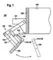
- FIG. 1 shows a top view of the installation household appliance 100 according to the invention. It comprises a hinge device 150 for hinging a door 250 on the furniture body 200 of the installation household appliance designed as Einbaukarllte réelle, of which only one side wall in FIG. 1 hatched is drawn.
- the hinge device 150 comprises a plurality of hinge elements 151... 155, which cooperate in such a way that a desired opening and closing movement of the door 250 with respect to the furniture body 200 is realized.
- this opening and closing movement in FIG. 1 indicated by a double arrow indicated there, it comes in particular with wide open door 250 to form a gap S between an edge of the door 250 and, for example, the front of the first furniture body 200 adjacent second furniture body 300.
- This gap S has a Vedetzungsrisiko than that foreign objects, in particular limbs of a user of the furniture body or the built-in household appliance, in the gap in a movement of the door 250 can be pinched or crushed. Due to the described risk of injury, the gap also entails a considerable risk of product liability and damage, especially in the USA.
- the hinge 100 further comprises a sensor device 110 for monitoring the gap S with respect to the foreign body (see FIG. 3 ) and a blocking device 130 for blocking the hinge device 150 upon detection of a foreign body by the sensor device 110 in the gap S.
- the blocking device 130 acts, as described, either directly or indirectly via a drive auxiliary device 140 FIG. 1 for example, a simple linkage, on the hinge means 150, in FIG. 1 for example, the hinge element 155.
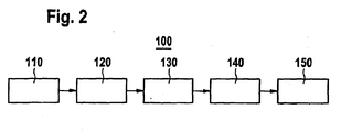
- FIG. 2 is the interaction according to the invention of the individual components of the built-in household appliance 100, that is, the inventive method illustrated.
- the sensor device 110 monitors, as stated, the gap S with respect to a foreign body 400.
- the sensor device 110 generates in response to the presence of the foreign body, a trigger signal for triggering a blockage of the hinge means 150 by the blocking device 130.
- the trigger signal depending on the design of the Sensor device 110 may be formed electrically or mechanically.
- a mechanically formed trigger signal may, for example, be represented by the movement of a body.
- the transmission device 120 may, for example, be in the form of an amplifier or relay and in the case of a mechanical triggering signal in the form of a linkage or gearbox.
- the blocking device does not act directly but indirectly on the hinge device 150 or its elements 151... 155 via the control auxiliary device 140.
- the blocking device 130 is designed so that it prevents injury to the foreign body 400, that is, in particular the pinching of limbs, in the gap S. Specifically, the blocking device 130 ensures this by either completely blocking the movement of the hinge means 150, and thus the door 250 hinged thereto, or by causing only movement of the hinge means 150 in FIG allows such a direction, which would have an enlargement of the gap S and thus a discharge of a potentially trapped foreign body result.
- FIG. 3 shows an example of the design of the sensor device 110 as a mechanical pressure sensor device.
- the sensor device 110 consists of a force transmission element 112, which is formed for example as a flexible plate member.
- This power transmission element 112 is displaceably guided, for example, in the door 250 by means of a guide device 114. It extends perpendicular to the plane of the drawing, preferably over the entire length or height of the gap S and projects into the one end into it. With its other end it is non-positively coupled to the transmission device 120 or directly to the blocking device 130.
- the force transmission element 112 As soon as the force acting on the force transmission element 112 decreases, either because the foreign body 400 has been removed from the gap or because the pivotal movement of the door 250 has been reversed, the force transmission element is advantageously pushed back into its starting position, for example by a return spring 116, so that it possibly protrudes again as a sensor in the gap S.
Landscapes
- Engineering & Computer Science (AREA)
- Mechanical Engineering (AREA)
- Chemical & Material Sciences (AREA)
- Combustion & Propulsion (AREA)
- Physics & Mathematics (AREA)
- Thermal Sciences (AREA)
- General Engineering & Computer Science (AREA)
- Power-Operated Mechanisms For Wings (AREA)
- Hinges (AREA)
- Specific Sealing Or Ventilating Devices For Doors And Windows (AREA)
- Disintegrating Or Milling (AREA)
- Filters For Electric Vacuum Cleaners (AREA)
Description
- Die Erfindung betrifft ein Einbauhaushaltsgerät, insbesondere ein Einbaukältegerät mit Scharnieren zum Anlenken einer Türe an dem Möbelkorpus, des Einbau-Haushaltsgerätes. Darüber hinaus betrifft die Erfindung ein Verfahren zum Betreiben des Einbauhaushaltsgerätes.
- Derartige Einbauhaushaltsgeräte mit Scharnieren sind im Stand der Technik grundsätzlich bekannt. Sie sind typischerweise so ausgebildet, dass sie eine vorbestimmte Öffnungs- und Schließbewegung für die Türe relativ zu dem Möbelkorpus realisieren. Insbesondere bei Einbau-Haushaltsgeräten für den US-amerikanischen Markt bildet sich zwischen einem insbesondere vertikalen Rand der Türe des ersten Möbelkorpus und der Front eines zu dem ersten Möbelkorpus benachbarten zweiten Möbelkorpus ein Spalt aus. Dieser Spalt birgt ein erhebliches Gefährdungspotential für den Benutzer des Einbau-Haushaltsgerätes, weil dessen Gliedmaßen bei einem (unbeabsichtigten) Eingriff in den Spalt möglicherweise gequetscht werden können. Insbesondere in den USA geht dieses Gefährdungspotential einher mit dem Risiko erheblicher Schadenersatzforderungen gegen den Hersteller des Einbau-Haushaltsgerätes.
- Zu einer ganz ähnlichen Problemstellung, nämlich der Verletzungs- und insbesondere Einquetschgefahr von Gliedmaßen eines Benutzers eines Einbau-Haushaltsgerätes bei einem unbeabsichtigten Eingriff in ein Scharnier, ist aus dem Stand der Technik eine Lösung bekannt, welche in der Offenlegungsschrift
DE 44 18 238 A1 offenbart ist. Diese Offenlegungsschrift lehrt, bei einem mehrgelenkigen Scharnier eine Abdeckung vorzusehen, welche das Scharnier während vorzugsweise aller möglichen Schwenkbewegungen gegen einen Eingriff abkapselt. Diese Abdeckung weist ein elastisches Plattenelement in Form einer elastischen Zunge auf, welches sich in Richtung der Länge eines Spaltes zwischen der Türe und dem Korpus des Einbau-Küchengerätes, das heißt typischerweise in vertikaler Richtung, erstreckt, aber in seiner Länge bzw. Höhe auf die Höhe des Scharniers beschränkt ist. - Der Erfindung liegt die Aufgabe zugrunde, mit einfachen konstruktiven Maßnahmen, ein Verletzungs-, insbesondere Einquetschrisiko, welches von einem unvermeidlichen Spalt zwischen einem Rand der Türe des ersten Möbelkorpus und der Front eines zu dem ersten Möbelkorpus benachbarten zweiten Möbelkorpus ausgeht, zu reduzieren.
- Diese Aufgabe wird durch den Gegenstand des Patentanspruchs 1 gelöst. Das durch diesen Gegenstand bezeichnete Einbauhaushaltsgerät ist gekennzeichnet durch eine Sensoreinrichtung zum Überwachen des Spaltes im Hinblick auf einen Fremdkörper und eine Blockierungseinrichtung zum Blockieren der Scharniereinrichtung bei Vorhandensein eines von der Sensoreinrichtung detektierten Fremdkörpers in einer Bewegungsrichtung der Türe, welche eine weitere Verkleinerung des Spaltes zur Folge hätte.
- Die beanspruchte Ausgestaltung des Einbauhaushaltsgeräts mit einer Sensoreinrichtung ermöglicht insbesondere das Erkennen eines Fremdkörpers zum Beispiel in Form von Gliedmaßen eines Benutzers des Möbelkorpus beziehungsweise des Einbau-Haushaltsgerätes in dem Spalt. Weiterhin ermöglicht die beanspruchte Ausgestaltung die Einleitung geeigneter Gegenmaßnahmen, um ein Einquetschen der Gliedmaßen zu verhindern beziehungsweise diesem entgegenzuwirken. Derartige Gegenmaßnahmen werden mit Hilfe der beanspruchten Blockierungseinrichtung realisiert, indem diese die Scharniereinrichtung bei Vorhandensein eines detektierten Fremdkörpers entweder vollständig blockiert, so dass keine Bewegung des Scharniers und der daran angelenkten Türe mehr möglich ist, oder nur noch eine Bewegung der Türe möglich ist, welche eine Vergrößerung des Spaltes zur Folge hätte. Insbesondere in letztem Fall kann der eingeklemmte Fremdkörper dann problemlos wieder aus dem Spalt entfernt werden. Die beanspruchte Erfindung trägt nicht nur wesentlich zur Reduzierung des Verletzungsrisikos des Benutzers, sondern vorteilhafterweise auch wesentlich zu einer Reduzierung des Haftungsrisikos für den Anbieter bzw. Hersteller der Möbelkorpusse beziehungsweise der Einbau-Haushaltsgeräte bei.
- Vorteilhafterweise eignen sich als Sensoreinrichtungen sowohl elektrische wie auch mechanische Drucksensoreinrichtungen, welche auf eine durch den Fremdkörper in dem Spalt auf sie ausgeübte Krafteinwirkung reagieren und den Fremdkörper auf diese Weise detektieren. Alternativ oder zusätzlich zu einer Ausbildung als Drucksensoreinrichtung kann die Sensoreinrichtung auch als Kameraeinrichtung oder als Bewegungsmelder zum optischen Detektieren des Fremdkörpers in dem Spalt ausgebildet sein.
- Vorteilhafterweise ist zwischen der Sensoreinrichtung und der Blockierungseinrichtung eine elektrische oder mechanische Übertragungseinrichtung zum Übertragen und/oder Übersetzen eines von der Sensoreinrichtung generierten Auslösesignals an die Blockierungseinrichtung vorhanden.
- Weiterhin kann es vorteilhaft sein, wenn die Blockierungseinrichtung nicht direkt, sondern indirekt über eine Ansteuer-Hilfseinrichtung auf die Scharniereinrichtung und insbesondere deren Scharnierelemente einwirkt.
- Weitere vorteilhafte Ausgestaltungen des Scharniers sind Gegenstand der Unteransprüche.
- Die oben genannte Aufgabe der Erfindung wird weiterhin durch ein Verfahren zum Betreiben eines Einbauhaushaltsgeräts mit Scharnieren zum Anlenken einer Türe an einen Möbelkorpus gelöst. Die Vorteile dieser Lösung entsprechen den oben in Bezug auf das beanspruchte Einbauhaushaltsgerät genannten Vorteilen.
- Der Erfindung sind insgesamt drei Figuren beigefügt, wobei
-
Figur 1 eine Draufsicht auf ein ausschnittsweise darsgestelltes Einbauhaushaltsgerät mit einer Scharniervorrichtung -
Figur 2 das Zusammenwirken einzelner Elemente der Scharniervorrichtung; und -
Figur 3 ein Ausführungsbeispiel für den erfindungsgemäßen Drucksensor zeigt. - Die Erfindung wird nachfolgend unter Bezugnahme auf die genannten Figuren detailliert beschrieben. In allen Figuren sind gleiche Elemente mit gleichen Bezugszeichen bezeichnet.
-
Figur 1 zeigt eine Draufsicht auf das erfindungsgemäße Einbauhaushaltsgerät 100. Es umfasst eine Scharniereinrichtung 150 zum Anlenken einer Türe 250 an dem Möbelkorpus 200 des als Einbaukälltegerät ausgebildeten Einbauhaushaltsgeräts, von dem nur eine Seitenwand inFigur 1 schraffiert eingezeichnet ist. Die Scharniereinrichtung 150 umfasst eine Mehrzahl von Scharnierelementen 151...155, welche in der Weise zusammenwirken, dass eine gewünschte Öffnungs- und Schließbewegung der Türe 250 in Bezug auf den Möbelkorpus 200 realisiert wird. Bei dieser Öffnungs- und Schließbewegung, inFigur 1 durch einen dort eingezeichneten Doppelpfeil angedeutet, kommt es insbesondere bei weit geöffneter Türe 250 zur Ausbildung eines Spaltes S zwischen einem Rand der Türe 250 und beispielsweise der Front eines zu dem ersten Möbelkorpus 200 benachbarten zweiten Möbelkorpus 300. Dieser Spalt S birgt insofern ein Vedetzungsrisiko, als dass Fremdkörper, insbesondere Gliedmaßen von einem Benutzer des Möbelkorpus beziehungsweise des Einbau-Haushaltsgerätes, in dem Spalt bei einer Bewegung der Türe 250 eingeklemmt oder gequetscht werden können. Aufgrund des beschriebenen Verletzungsrisikos birgt der Spalt insbesondere in den USA auch ein erhebliches Produkthaftungs- und Schadenersatzrisiko. - Um die beschriebenen Risiken zu vermeiden, umfasst das erfindungsgemäße Scharnier 100 weiterhin eine Sensoreinrichtung 110 zum Überwachen des Spaltes S im Hinblick auf den Fremdkörper (siehe
Figur 3 ) und eine Blockierungseinrichtung 130 zum Blockieren der Scharniereinrichtung 150 bei Detektion eines Fremdkörpers durch die Sensoreinrichtung 110 in dem Spalt S. Die Blockierungseinrichtung 130 wirkt, wie beschrieben, entweder direkt oder indirekt über eine Ansteuer-Hilfseinrichtung 140, inFigur 1 beispielsweise ein einfaches Gestänge, auf die Scharniereinrichtung 150, inFigur 1 beispielsweise das Scharnierelement 155. - In
Figur 2 ist das erfindungsgemäße Zusammenwirken der einzelnen Komponenten des Einbauhaushaltsgeräts 100, das heißt das erfindungsgemäße Verfahren, veranschaulicht. Die Sensoreinrichtung 110 überwacht, wie gesagt, den Spalt S im Hinblick auf einen Fremdkörper 400. Die Sensoreinrichtung 110 generiert im Ansprechen auf das Vorhandensein des Fremdkörpers ein Auslösesignal zum Auslösen einer Blockierung der Scharniereinrichtung 150 durch die Blockierungseinrichtung 130. Das Auslösesignal kann je nach Ausbildung der Sensoreinrichtung 110 elektrisch oder mechanisch ausgebildet sein. Ein mechanisch ausgebildetes Auslösesignal kann zum Beispiel durch die Bewegung eines Körpers repräsentiert sein. Je nach lokalen Gegebenheiten und Ausbildung des bei dem Einbauhaushaltsgerät zum Einsatz kommenden Scharniers kann es vorteilhaft sein, wenn das Auslösesignal nicht direkt, sondern über eine elektrische oder mechanische Übertragungseinrichtung 120 an die Blockierungseinrichtung 130 geleitet wird. Bei einem elektrischen Signal kann die Übertragungseinrichtung 120 zum Beispiel in Form eines Verstärkers oder Relais und im Fall eines mechanischen Auslösesignals in Form eines Gestänges oder Getriebes ausgebildet sein. - Analog kann es je nach Einbausituation und Ausbildung der Scharniereinrichtung 150 vorteilhaft sein, wenn die Blockierungseinrichtung nicht direkt, sondern indirekt über die Ansteuer-Hilfseinrichtung 140 auf die Scharniereinrichtung 150 oder deren Elemente 151...155 einwirkt.
- Die Blockierungseinrichtung 130 ist erfindungsgemäß so ausgelegt, dass sie eine Verletzung des Fremdkörpers 400, das heißt insbesondere das Einklemmen von Gliedmaßen, in dem Spalt S verhindert. Konkret gewährleistet die Blockierungseinrichtung 130 dies, indem sie entweder die Bewegung der Scharniereinrichtung 150 und damit der daran angelenkten Türe 250 vollständig blockiert oder indem sie nur eine Bewegung der Scharniereinrichtung 150 in einer solchen Richtung zulässt, welche eine Vergrößerung des Spaltes S und damit eine Entlastung eines eventuell eingeklemmten Fremdkörpers zur Folge hätte.
-
Figur 3 zeigt ein Beispiel für die Ausbildung der Sensoreinrichtung 110 als mechanische Drucksensoreinrichtung. In diesem Fall besteht die Sensoreinrichtung 110 aus einem Kraftübertragungselement 112, welches beispielsweise als biegsames Plattenelement gebildet ist. Dieses Kraftübertragungselement 112 ist zum Beispiel in der Türe 250 mit Hilfe einer Führungseinrichtung 114 verschiebbar geführt. Es erstreckt sich senkrecht zur Zeichenebene vorzugsweise über die gesamte Länge beziehungsweise Höhe des Spaltes S und ragt mit dem einen Ende in diesen hinein. Mit seinem anderen Ende ist es kraftschlüssig mit der Übertragungseinrichtung 120 oder direkt mit der Blockierungseinrichtung 130 gekoppelt. Bei Vorhandensein des Fremdkörpers 400 in dem Spalt S übt dieser im Falle einer Schwenkbewegung der Türe 250 in Pfeilrichtung P eine Kraft auf das in den Spalt S hineinragende Ende des Kraftübertragungselementes 112 aus. Diese Kraft überträgt sich dann vorzugsweise als mechanisches Auslösesignal, wie bereits oben angedeutet, entweder auf die Übertragungseinrichtung 120 oder direkt auf die Blockierungseinrichtung 130. Die Blockierungseinrichtung 130 würde dann in diesem Fall die Bewegung der Türe 250 in Pfeilrichtung P stoppen oder umkehren. Sobald die auf das Kraftübertragungselement 112 einwirkende Kraft nachlässt, sei es entweder weil der Fremdköper 400 aus dem Spalt entfernt wurde oder weil die Schwenkbewegung der Türe 250 umgekehrt wurde, wird das Kraftübertragungselement vorteilhafterweise zum Beispiel durch eine Rückholfeder 116 wieder in seine Ausgangsposition geschoben, so dass es gegebenenfalls wieder als Fühler in den Spalt S hineinragt.
Claims (9)
- Einbauhaushaltsgerät (100), insbesondere Einbaukältegerät mit
Scharnieren (150) zum Anlenken einer Türe (250) an dem Möbelkorpus (200), des Einbauhaushaltsgerätes, wobei die Scharniereinrichtung (150) ausgebildet ist, eine Offnungs- und Schließbewegung der Türe (250) zu realisieren, bei welcher sich zwischen einem Rand der Türe (250) und der Front des Möbelkorpus (200) des Einbauhaushaltsgerätes benachbarten zweiten Möbelkorpus (300) ein Spalt (S) ausbildet;
gekennzeichnet durch
eine Sensoreinrichtung (110) zum Überwachen des Spaltes (S) im Hinblick auf einen Fremdkörper (400); und
eine Blockierungseinrichtung (130) zum Blockieren der Scharniereinrichtung (150) bei Vorhandensein eines von der Sensoreinrichtung detektierten Fremdkörpers (400) in einer Bewegungsrichtung der Türe (250), welche eine weitere Verkleinerung des Spaltes (S) zur Folge hätte. - Einbauhaushaltsgerät (100) nach Anspruch 1, dadurch gekennzeichnet, dass die Sensoreinrichtung (110) als elektrische oder mechanische Drucksensoreinrichtung ausgebildet ist zum Erzeugen eines elektrischen oder mechanischen Auslösesignals, welches das Vorhandensein des Fremdkörpers (400) anzeigt, wenn der insbesondere durch den Fremdkörper (400) auf die Drucksensoreinrichtung ausgeübte Druck einen vorbestimmten Druckschwellenwert übersteigt.
- Einbauhaushaltsgerät (100) nach Anspruch 2, dadurch gekennzeichnet, dass die mechanische Drucksensoreinrichtung (110) ein Kraftübertragungselement (112) aufweist, welches zumindest stellenweise in den Spalt (S) hinragt und an oder in der Türe (250) beweglich gelagert ist zum Erzeugen des mechanischen Auslösesignals in Form einer Bewegung des Kraftübertragungselementes (112) im Ansprechen auf eine von dem Fremdkörper (400) in dem Spalt bewirkte Krafteinwirkung auf das Kraftübertragungselement (112).
- Einbauhaushaltsgerät (100) nach Anspruch 1, dadurch gekennzeichnet, dass die Sensoreinrichtung (110) als Kameraeinrichtung oder Bewegungsmelder ausgebildet ist zum Erzeugen des elektrischen Auslösesignals im Ansprechen auf das Vorhandensein des Fremdkörpers (400) in dem Spalt (S).
- Einbauhaushaltsgerät (100) nach einem der Ansprüche 2 bis 4, gekennzeichnet durch eine elektrische oder mechanische Übertragungseinrichtung (120) zum Übertragen des elektrischen oder mechanischen Auslösesignals an die Blockierungseinrichtung (130).
- Einbauhaushaltsgerät (100) nach einem der vorangegangenen Ansprüche, dadurch gekennzeichnet, dass die Scharniereinrichtung (150) eine Mehrzahl von beweglichen Schamierelementen (151...155) aufweist, welche zur Realisierung der gewünschten Öffnungs- und Schließbewegung der Türe (250) in geeigneter Weise zusammenwirken.
- Einbauhaushaltsgerät (100) nach Anspruch 6, dadurch gekennzeichnet, dass die Blockierungseinrichtung (130) ausgebildet ist, die Relativbewegung von einem der Scharnierelemente (155) zu einem anderen der Scharnierelemente (151....-154) oder zu der Türe (250) oder zu einem der Möbelkorpusse (200, 300) durch eine direkte oder indirekte Einwirkung so zu begrenzen, dass eine Bewegung der Türe (250) entweder nicht mehr oder nur noch in eine Richtung, welche eine Vergrößerung des Spaltes (S) zur Folge hätte, möglich ist.
- Einbauhaushaltsgerät (100) nach Anspruch 7, gekennzeichnet durch eine zwischen der Blockierungseinrichtung (130) und zumindest einem der Scharnierelemente (155) vorgesehene Ansteuer-Hilfseinrichtung (140) zum indirekten Ansteuern des Scharnierelementes (155) durch die Blockierungseinrichtung (130).
- Verfahren zum Betreiben eines Einbauhaushaltsgeräts, insbesondere Einbauhaushaltsgerät mit Scharnieren (150) zum Anlenken einer Türe (250) an dem Möbelkorpus (200) des Einbau-Haushaltsgerät, umfassend die Schritte:Schwenken der Türe (250) so, dass sich zwischen einem Rand der Türe (250) und der Front eines zu dem Möbelkorpus (200) des Einbauhaushaltsgeräts benachbarten zweiten Möbelkorpus (300) ein Spalt (S) ausbildet;gekennzeichnet durchÜberwachen des Spaltes (S) im Hinblick auf einen Fremdkörper (400); und Blockieren der Scharniereinrichtung (150) bei Vorhandensein eines detektierten Fremdkörpers (400) in einer Bewegungsrichtung der Türe (250), welche eine weitere Verkleinerung des Spaltes (S) zur Folge hätte.
Applications Claiming Priority (2)
| Application Number | Priority Date | Filing Date | Title |
|---|---|---|---|
| DE102004062235A DE102004062235A1 (de) | 2004-12-23 | 2004-12-23 | Einbauhaushaltsgerät |
| PCT/EP2005/056345 WO2006069882A1 (de) | 2004-12-23 | 2005-11-30 | Einbauhaushaltsgerät |
Publications (2)
| Publication Number | Publication Date |
|---|---|
| EP1831490A1 EP1831490A1 (de) | 2007-09-12 |
| EP1831490B1 true EP1831490B1 (de) | 2009-03-11 |
Family
ID=36088278
Family Applications (1)
| Application Number | Title | Priority Date | Filing Date |
|---|---|---|---|
| EP05850019A Expired - Lifetime EP1831490B1 (de) | 2004-12-23 | 2005-11-30 | Einbauhaushaltsgerät |
Country Status (6)
| Country | Link |
|---|---|
| US (1) | US7748083B2 (de) |
| EP (1) | EP1831490B1 (de) |
| AT (1) | ATE425335T1 (de) |
| DE (2) | DE102004062235A1 (de) |
| ES (1) | ES2323145T3 (de) |
| WO (1) | WO2006069882A1 (de) |
Families Citing this family (9)
| Publication number | Priority date | Publication date | Assignee | Title |
|---|---|---|---|---|
| DE202007005957U1 (de) * | 2007-02-19 | 2008-06-26 | Liebherr-Hausgeräte Ochsenhausen GmbH | Kühl- und/oder Gefriergerät |
| DE102013001402B4 (de) * | 2013-01-28 | 2016-06-09 | Apparatebau Gronbach GmbH | Scharnier für einen Herd sowie Herd |
| AT514056B1 (de) * | 2013-05-08 | 2014-10-15 | Blum Gmbh Julius | Anordnung mit Scharnier, Linearführung und Sensorvorrichtung |
| DE102014018686A1 (de) * | 2014-12-18 | 2016-06-23 | Huf Hülsbeck & Fürst Gmbh & Co. Kg | Moduleinheit für ein Kraftfahrzeug |
| DE102014018687A1 (de) | 2014-12-18 | 2016-06-23 | Huf Hülsbeck & Fürst Gmbh & Co. Kg | Moduleinheit für ein Kraftfahrzeug |
| US10233664B2 (en) * | 2015-09-24 | 2019-03-19 | Campvalley (Xiamen) Co., Ltd. | Tent and tent frame with illumination |
| WO2018075094A1 (en) * | 2016-10-17 | 2018-04-26 | Whirlpool Corporation | Hinge assembly |
| DE102017218698A1 (de) * | 2017-10-19 | 2019-04-25 | BSH Hausgeräte GmbH | Einbauhaushaltskältegerät mit einem Türpositionserfassungssystem |
| CN119593654B (zh) * | 2023-09-08 | 2025-11-14 | 宁波方太厨具有限公司 | 用于家用电器的门铰链、家用电器及家用电器开关门控制方法 |
Family Cites Families (16)
| Publication number | Priority date | Publication date | Assignee | Title |
|---|---|---|---|---|
| US853507A (en) | 1906-03-30 | 1907-05-14 | Christopher Fielding | Hinge. |
| US3231880A (en) * | 1962-06-18 | 1966-01-25 | Stefan M Stein | Detection response mechanism |
| AT348375B (de) | 1972-12-07 | 1979-02-12 | Blum Gmbh Julius | Einstellbares scharnier mit einem oeffnungs- winkel von 90grad, mit einem an einem bauteil, beispielsweise fachbrett, befestigbaren grundkoerper und einem vorzugsweise in eine klappe einsetzbaren gehaeuse |
| FR2420633A1 (fr) | 1978-03-23 | 1979-10-19 | Renault | Charniere a double articulation notamment pour l'articulation d'un hayon |
| US5265954A (en) * | 1989-02-21 | 1993-11-30 | Whirlpool Corporation | Refrigerator door hinge assembly |
| US5074073A (en) * | 1990-10-17 | 1991-12-24 | Zwebner Ascher Z | Car door safety device |
| DE4418238A1 (de) | 1994-05-25 | 1995-11-30 | Bosch Siemens Hausgeraete | Mehrgelenkiges Scharnier |
| DE19507624A1 (de) | 1995-03-04 | 1996-09-05 | Lautenschlaeger Mepla Werke | Kreuzgelenkscharnier |
| US5566504A (en) * | 1995-04-03 | 1996-10-22 | Pitel; John A. | Combination door gasket and safety edge strip |
| JPH09228733A (ja) | 1996-02-28 | 1997-09-02 | Matsushita Electric Works Ltd | 折り畳み扉及び収納キャビネット |
| US20040055110A1 (en) * | 1997-03-17 | 2004-03-25 | Breed David S. | Method and apparatus for controlling a vehicle door |
| US6145918A (en) * | 1999-10-08 | 2000-11-14 | Meritor Light Vehicle Systems, Llc | Anti-pinch door lock |
| AUPR691101A0 (en) * | 2001-08-09 | 2001-08-30 | Francis De La Coeur, Neil | Safety device |
| US6591453B2 (en) | 2001-09-14 | 2003-07-15 | John E. Jenks | Locking hinge system |
| DE10208057A1 (de) * | 2002-02-25 | 2003-09-04 | Bsh Bosch Siemens Hausgeraete | Türöffnungssensor und damit ausgestattetes Kältegerät |
| CN1291127C (zh) * | 2002-03-01 | 2006-12-20 | 盖慈有限公司 | 传动装置 |
-
2004
- 2004-12-23 DE DE102004062235A patent/DE102004062235A1/de not_active Withdrawn
-
2005
- 2005-11-30 EP EP05850019A patent/EP1831490B1/de not_active Expired - Lifetime
- 2005-11-30 DE DE502005006848T patent/DE502005006848D1/de not_active Expired - Lifetime
- 2005-11-30 WO PCT/EP2005/056345 patent/WO2006069882A1/de not_active Ceased
- 2005-11-30 ES ES05850019T patent/ES2323145T3/es not_active Expired - Lifetime
- 2005-11-30 US US11/794,215 patent/US7748083B2/en not_active Expired - Fee Related
- 2005-11-30 AT AT05850019T patent/ATE425335T1/de not_active IP Right Cessation
Also Published As
| Publication number | Publication date |
|---|---|
| DE502005006848D1 (de) | 2009-04-23 |
| US20080000051A1 (en) | 2008-01-03 |
| DE102004062235A1 (de) | 2006-07-13 |
| EP1831490A1 (de) | 2007-09-12 |
| ATE425335T1 (de) | 2009-03-15 |
| US7748083B2 (en) | 2010-07-06 |
| WO2006069882A1 (de) | 2006-07-06 |
| ES2323145T3 (es) | 2009-07-07 |
Similar Documents
| Publication | Publication Date | Title |
|---|---|---|
| AT512156B1 (de) | Anordnung zum Bewegen eines bewegbaren Möbelteils | |
| DE10202371B4 (de) | Verschluss für Türen, Hauben, Klappen od. dgl., insbesondere von Fahrzeugen, wie Kraftfahrzeugen | |
| DE102011050914A1 (de) | Geschirrspülmaschine | |
| WO2011095476A1 (de) | Auszugsführung eines schubkastens | |
| EP2857621A1 (de) | Scharnier für ein Möbelteil und Möbel | |
| DE102021100347A1 (de) | Haushaltsgerät, insbesondere Geschirrspülmaschine | |
| DE202008007432U1 (de) | Ausstoßeinrichtung | |
| DE102013114309A1 (de) | Einzugs- und Dämpfungseinheit für ein Schiebeelement | |
| DE102006061083A1 (de) | Kältegerät mit Türöffnungshilfe | |
| DE60221706T2 (de) | Schlupfklappe zum ein- und ausschlüpfen von kleintieren | |
| WO2006069882A1 (de) | Einbauhaushaltsgerät | |
| EP2660544A2 (de) | Kühl-und/oder Gefriergerät | |
| DE69316904T2 (de) | Vorrichtung zur gelenkigen Verbindung und Kuppeln einer Tür eines zum Einbau in einen Möbelelement bestimmten elektrischen Einbaugerätes an einem Türpaneel des Möbelementes, sa dass der Raum des Möbelelementes optimal benutzt wird | |
| CH646041A5 (en) | Cabinet-shaped housing for a household appliance, e.g. dishwasher | |
| EP2649263B1 (de) | Gliedertorflügel, gliedertorvorrichtung und betriebsverfahren | |
| WO2009132974A1 (de) | Haushaltsgerät | |
| EP2620575B1 (de) | Öffnungsunterstützungsvorrichtung für ein Fenster, eine Tür oder dergleichen sowie ein entsprechendes Fenster | |
| EP2734100B1 (de) | Geschirrspülmaschine und verfahren zum öffnen einer tür einer geschirrspülmaschine | |
| EP2120646B1 (de) | Möbelkorpus mit einer dichtlippe und einem ausstosser | |
| WO2010130440A1 (de) | VORRICHTUNG ZUR SCHLIEßFOLGEREGELUNG | |
| DE202005016584U1 (de) | Magnetische Türschließvorrichtung | |
| CH657570A5 (de) | Einwurftuer an einer ballenpresse. | |
| WO2006069880A1 (de) | Einbauhaushaltsgerät | |
| DE202004011009U1 (de) | Schließvorrichtung, insbesondere für Möbelschubladen | |
| DE102010003897A1 (de) | Scharnier für eine Hausgerätetür |
Legal Events
| Date | Code | Title | Description |
|---|---|---|---|
| PUAI | Public reference made under article 153(3) epc to a published international application that has entered the european phase |
Free format text: ORIGINAL CODE: 0009012 |
|
| 17P | Request for examination filed |
Effective date: 20070723 |
|
| AK | Designated contracting states |
Kind code of ref document: A1 Designated state(s): AT BE BG CH CY CZ DE DK EE ES FI FR GB GR HU IE IS IT LI LT LU LV MC NL PL PT RO SE SI SK TR |
|
| RIN1 | Information on inventor provided before grant (corrected) |
Inventor name: FEINAUER, ADOLF Inventor name: HEGER, BERND |
|
| DAX | Request for extension of the european patent (deleted) | ||
| GRAP | Despatch of communication of intention to grant a patent |
Free format text: ORIGINAL CODE: EPIDOSNIGR1 |
|
| GRAS | Grant fee paid |
Free format text: ORIGINAL CODE: EPIDOSNIGR3 |
|
| GRAA | (expected) grant |
Free format text: ORIGINAL CODE: 0009210 |
|
| AK | Designated contracting states |
Kind code of ref document: B1 Designated state(s): AT BE BG CH CY CZ DE DK EE ES FI FR GB GR HU IE IS IT LI LT LU LV MC NL PL PT RO SE SI SK TR |
|
| REG | Reference to a national code |
Ref country code: GB Ref legal event code: FG4D Free format text: NOT ENGLISH |
|
| REG | Reference to a national code |
Ref country code: CH Ref legal event code: EP |
|
| REG | Reference to a national code |
Ref country code: IE Ref legal event code: FG4D Free format text: LANGUAGE OF EP DOCUMENT: GERMAN |
|
| REF | Corresponds to: |
Ref document number: 502005006848 Country of ref document: DE Date of ref document: 20090423 Kind code of ref document: P |
|
| REG | Reference to a national code |
Ref country code: ES Ref legal event code: FG2A Ref document number: 2323145 Country of ref document: ES Kind code of ref document: T3 |
|
| PG25 | Lapsed in a contracting state [announced via postgrant information from national office to epo] |
Ref country code: NL Free format text: LAPSE BECAUSE OF FAILURE TO SUBMIT A TRANSLATION OF THE DESCRIPTION OR TO PAY THE FEE WITHIN THE PRESCRIBED TIME-LIMIT Effective date: 20090311 Ref country code: FI Free format text: LAPSE BECAUSE OF FAILURE TO SUBMIT A TRANSLATION OF THE DESCRIPTION OR TO PAY THE FEE WITHIN THE PRESCRIBED TIME-LIMIT Effective date: 20090311 Ref country code: LT Free format text: LAPSE BECAUSE OF FAILURE TO SUBMIT A TRANSLATION OF THE DESCRIPTION OR TO PAY THE FEE WITHIN THE PRESCRIBED TIME-LIMIT Effective date: 20090311 Ref country code: SI Free format text: LAPSE BECAUSE OF FAILURE TO SUBMIT A TRANSLATION OF THE DESCRIPTION OR TO PAY THE FEE WITHIN THE PRESCRIBED TIME-LIMIT Effective date: 20090311 |
|
| NLV1 | Nl: lapsed or annulled due to failure to fulfill the requirements of art. 29p and 29m of the patents act | ||
| PG25 | Lapsed in a contracting state [announced via postgrant information from national office to epo] |
Ref country code: PL Free format text: LAPSE BECAUSE OF FAILURE TO SUBMIT A TRANSLATION OF THE DESCRIPTION OR TO PAY THE FEE WITHIN THE PRESCRIBED TIME-LIMIT Effective date: 20090311 Ref country code: LV Free format text: LAPSE BECAUSE OF FAILURE TO SUBMIT A TRANSLATION OF THE DESCRIPTION OR TO PAY THE FEE WITHIN THE PRESCRIBED TIME-LIMIT Effective date: 20090311 Ref country code: SE Free format text: LAPSE BECAUSE OF FAILURE TO SUBMIT A TRANSLATION OF THE DESCRIPTION OR TO PAY THE FEE WITHIN THE PRESCRIBED TIME-LIMIT Effective date: 20090611 |
|
| REG | Reference to a national code |
Ref country code: IE Ref legal event code: FD4D |
|
| PG25 | Lapsed in a contracting state [announced via postgrant information from national office to epo] |
Ref country code: IE Free format text: LAPSE BECAUSE OF FAILURE TO SUBMIT A TRANSLATION OF THE DESCRIPTION OR TO PAY THE FEE WITHIN THE PRESCRIBED TIME-LIMIT Effective date: 20090311 Ref country code: EE Free format text: LAPSE BECAUSE OF FAILURE TO SUBMIT A TRANSLATION OF THE DESCRIPTION OR TO PAY THE FEE WITHIN THE PRESCRIBED TIME-LIMIT Effective date: 20090311 Ref country code: PT Free format text: LAPSE BECAUSE OF FAILURE TO SUBMIT A TRANSLATION OF THE DESCRIPTION OR TO PAY THE FEE WITHIN THE PRESCRIBED TIME-LIMIT Effective date: 20090824 Ref country code: CZ Free format text: LAPSE BECAUSE OF FAILURE TO SUBMIT A TRANSLATION OF THE DESCRIPTION OR TO PAY THE FEE WITHIN THE PRESCRIBED TIME-LIMIT Effective date: 20090311 |
|
| PG25 | Lapsed in a contracting state [announced via postgrant information from national office to epo] |
Ref country code: SK Free format text: LAPSE BECAUSE OF FAILURE TO SUBMIT A TRANSLATION OF THE DESCRIPTION OR TO PAY THE FEE WITHIN THE PRESCRIBED TIME-LIMIT Effective date: 20090311 Ref country code: RO Free format text: LAPSE BECAUSE OF FAILURE TO SUBMIT A TRANSLATION OF THE DESCRIPTION OR TO PAY THE FEE WITHIN THE PRESCRIBED TIME-LIMIT Effective date: 20090311 Ref country code: IS Free format text: LAPSE BECAUSE OF FAILURE TO SUBMIT A TRANSLATION OF THE DESCRIPTION OR TO PAY THE FEE WITHIN THE PRESCRIBED TIME-LIMIT Effective date: 20090711 |
|
| PLBE | No opposition filed within time limit |
Free format text: ORIGINAL CODE: 0009261 |
|
| STAA | Information on the status of an ep patent application or granted ep patent |
Free format text: STATUS: NO OPPOSITION FILED WITHIN TIME LIMIT |
|
| PG25 | Lapsed in a contracting state [announced via postgrant information from national office to epo] |
Ref country code: DK Free format text: LAPSE BECAUSE OF FAILURE TO SUBMIT A TRANSLATION OF THE DESCRIPTION OR TO PAY THE FEE WITHIN THE PRESCRIBED TIME-LIMIT Effective date: 20090311 Ref country code: BG Free format text: LAPSE BECAUSE OF FAILURE TO SUBMIT A TRANSLATION OF THE DESCRIPTION OR TO PAY THE FEE WITHIN THE PRESCRIBED TIME-LIMIT Effective date: 20090611 |
|
| 26N | No opposition filed |
Effective date: 20091214 |
|
| BERE | Be: lapsed |
Owner name: BSH BOSCH UND SIEMENS HAUSGERATE G.M.B.H. Effective date: 20091130 |
|
| PG25 | Lapsed in a contracting state [announced via postgrant information from national office to epo] |
Ref country code: MC Free format text: LAPSE BECAUSE OF NON-PAYMENT OF DUE FEES Effective date: 20091130 |
|
| REG | Reference to a national code |
Ref country code: CH Ref legal event code: PL |
|
| PG25 | Lapsed in a contracting state [announced via postgrant information from national office to epo] |
Ref country code: LI Free format text: LAPSE BECAUSE OF NON-PAYMENT OF DUE FEES Effective date: 20091130 Ref country code: CH Free format text: LAPSE BECAUSE OF NON-PAYMENT OF DUE FEES Effective date: 20091130 Ref country code: GR Free format text: LAPSE BECAUSE OF FAILURE TO SUBMIT A TRANSLATION OF THE DESCRIPTION OR TO PAY THE FEE WITHIN THE PRESCRIBED TIME-LIMIT Effective date: 20090612 Ref country code: BE Free format text: LAPSE BECAUSE OF NON-PAYMENT OF DUE FEES Effective date: 20091130 |
|
| PG25 | Lapsed in a contracting state [announced via postgrant information from national office to epo] |
Ref country code: AT Free format text: LAPSE BECAUSE OF NON-PAYMENT OF DUE FEES Effective date: 20091130 |
|
| PGFP | Annual fee paid to national office [announced via postgrant information from national office to epo] |
Ref country code: DE Payment date: 20101130 Year of fee payment: 6 |
|
| PGFP | Annual fee paid to national office [announced via postgrant information from national office to epo] |
Ref country code: TR Payment date: 20101125 Year of fee payment: 6 Ref country code: GB Payment date: 20101123 Year of fee payment: 6 Ref country code: IT Payment date: 20101126 Year of fee payment: 6 |
|
| PG25 | Lapsed in a contracting state [announced via postgrant information from national office to epo] |
Ref country code: LU Free format text: LAPSE BECAUSE OF NON-PAYMENT OF DUE FEES Effective date: 20091130 |
|
| PG25 | Lapsed in a contracting state [announced via postgrant information from national office to epo] |
Ref country code: HU Free format text: LAPSE BECAUSE OF FAILURE TO SUBMIT A TRANSLATION OF THE DESCRIPTION OR TO PAY THE FEE WITHIN THE PRESCRIBED TIME-LIMIT Effective date: 20090912 |
|
| PG25 | Lapsed in a contracting state [announced via postgrant information from national office to epo] |
Ref country code: CY Free format text: LAPSE BECAUSE OF FAILURE TO SUBMIT A TRANSLATION OF THE DESCRIPTION OR TO PAY THE FEE WITHIN THE PRESCRIBED TIME-LIMIT Effective date: 20090311 |
|
| PGFP | Annual fee paid to national office [announced via postgrant information from national office to epo] |
Ref country code: ES Payment date: 20111123 Year of fee payment: 7 Ref country code: FR Payment date: 20111125 Year of fee payment: 7 |
|
| GBPC | Gb: european patent ceased through non-payment of renewal fee |
Effective date: 20121130 |
|
| REG | Reference to a national code |
Ref country code: FR Ref legal event code: ST Effective date: 20130731 |
|
| PG25 | Lapsed in a contracting state [announced via postgrant information from national office to epo] |
Ref country code: IT Free format text: LAPSE BECAUSE OF NON-PAYMENT OF DUE FEES Effective date: 20121130 |
|
| REG | Reference to a national code |
Ref country code: DE Ref legal event code: R119 Ref document number: 502005006848 Country of ref document: DE Effective date: 20130601 |
|
| PG25 | Lapsed in a contracting state [announced via postgrant information from national office to epo] |
Ref country code: DE Free format text: LAPSE BECAUSE OF NON-PAYMENT OF DUE FEES Effective date: 20130601 |
|
| PG25 | Lapsed in a contracting state [announced via postgrant information from national office to epo] |
Ref country code: GB Free format text: LAPSE BECAUSE OF NON-PAYMENT OF DUE FEES Effective date: 20121130 Ref country code: FR Free format text: LAPSE BECAUSE OF NON-PAYMENT OF DUE FEES Effective date: 20121130 |
|
| REG | Reference to a national code |
Ref country code: ES Ref legal event code: FD2A Effective date: 20140304 |
|
| PG25 | Lapsed in a contracting state [announced via postgrant information from national office to epo] |
Ref country code: TR Free format text: LAPSE BECAUSE OF NON-PAYMENT OF DUE FEES Effective date: 20121130 Ref country code: ES Free format text: LAPSE BECAUSE OF NON-PAYMENT OF DUE FEES Effective date: 20121201 |