EP1831816B1 - Procedes et appareil pour l'eclairage de capture d'information - Google Patents
Procedes et appareil pour l'eclairage de capture d'information Download PDFInfo
- Publication number
- EP1831816B1 EP1831816B1 EP05853210A EP05853210A EP1831816B1 EP 1831816 B1 EP1831816 B1 EP 1831816B1 EP 05853210 A EP05853210 A EP 05853210A EP 05853210 A EP05853210 A EP 05853210A EP 1831816 B1 EP1831816 B1 EP 1831816B1
- Authority
- EP
- European Patent Office
- Prior art keywords
- illumination
- medium
- module
- narrow beam
- scanner
- Prior art date
- Legal status (The legal status is an assumption and is not a legal conclusion. Google has not performed a legal analysis and makes no representation as to the accuracy of the status listed.)
- Expired - Lifetime
Links
Images


Classifications
-
- G—PHYSICS
- G06—COMPUTING OR CALCULATING; COUNTING
- G06K—GRAPHICAL DATA READING; PRESENTATION OF DATA; RECORD CARRIERS; HANDLING RECORD CARRIERS
- G06K7/00—Methods or arrangements for sensing record carriers, e.g. for reading patterns
- G06K7/10—Methods or arrangements for sensing record carriers, e.g. for reading patterns by electromagnetic radiation, e.g. optical sensing; by corpuscular radiation
- G06K7/10544—Methods or arrangements for sensing record carriers, e.g. for reading patterns by electromagnetic radiation, e.g. optical sensing; by corpuscular radiation by scanning of the records by radiation in the optical part of the electromagnetic spectrum
- G06K7/10712—Fixed beam scanning
- G06K7/10722—Photodetector array or CCD scanning
- G06K7/10732—Light sources
-
- G—PHYSICS
- G06—COMPUTING OR CALCULATING; COUNTING
- G06K—GRAPHICAL DATA READING; PRESENTATION OF DATA; RECORD CARRIERS; HANDLING RECORD CARRIERS
- G06K19/00—Record carriers for use with machines and with at least a part designed to carry digital markings
- G06K19/06—Record carriers for use with machines and with at least a part designed to carry digital markings characterised by the kind of the digital marking, e.g. shape, nature, code
- G06K19/06009—Record carriers for use with machines and with at least a part designed to carry digital markings characterised by the kind of the digital marking, e.g. shape, nature, code with optically detectable marking
-
- G—PHYSICS
- G06—COMPUTING OR CALCULATING; COUNTING
- G06K—GRAPHICAL DATA READING; PRESENTATION OF DATA; RECORD CARRIERS; HANDLING RECORD CARRIERS
- G06K19/00—Record carriers for use with machines and with at least a part designed to carry digital markings
- G06K19/06—Record carriers for use with machines and with at least a part designed to carry digital markings characterised by the kind of the digital marking, e.g. shape, nature, code
- G06K19/063—Record carriers for use with machines and with at least a part designed to carry digital markings characterised by the kind of the digital marking, e.g. shape, nature, code the carrier being marginally punched or notched, e.g. having elongated slots
Definitions
- the invention is directed to methods and apparatus for capturing data and, more particularly to illuminating Direct Part Mark (DPM) dataforms.
- DPM Direct Part Mark
- UPC Universal Product Codes
- EAN European Article Numbers
- Dataforms are any indicia that encode numeric and other information in visual form.
- dataforms can be barcodes, two dimensional codes, marks on the object, labels, signatures, signs etc. Barcodes are comprised of a series of light and dark rectangular areas of different widths. The light and dark areas can be arranged to represent the numbers of a UPC. Additionally, dataforms are not limited to identifying products. They can be used to identify important objects, places, etc.
- Direct Part Marking is an important way to permanently mark objects for identification.
- the automotive and aerospace industries have decided to use DPM dataforms to identify their products.
- the surface of the object is modified to include dataforms, such as, for example, barcodes, two dimensional codes, etc.
- One exemplary method of marking is dot-peening, in which the surface of the object is impacted by a peening device, such as, for example, a stylus. Each impact creates a "crater", and a collection of craters can be used to form patterns that represent dataforms such as a DataMatrix TM .
- the crater may also have a slightly raised rim around its circumference created by the material displaced during the peening process.
- Other methods to create surface profile modifications comprise laser etching, chemical etching, and electro-chemical etching.
- Fig. 1 illustrates an exemplary dot-peened dataform 102.
- the circles represent craters on the surface of the object.
- the craters are arranged in an array that represents information.
- the dataform 102 can comprise information regarding the manufacturer, the UPC, the time, date and location of manufacture, etc. This information can be used for inventory, accountability, identification, recalls, etc.
- an extended light source is used to create a broad beam illumination.
- the background surface tends to show up bright, while the marked features, i.e., the dataform, shows up dark.
- a narrow beam illumination is created by a set of point light sources rather than a single point light source.
- the dataform is lit up brightly, while the surface of the object is left in relative darkness.
- Known scanners that use this dark field illumination method implement point light sources that are symmetrical about the optical system of their camera.
- one known scanner has a ring of 9 light emitting diodes (LEDs) that illuminate the dataform at the same time, while other scanners have a diffusing lightpipe that has a cylindrical extrusion that is designed to enclose the mark being scanned.
- LEDs light emitting diodes
- Other handheld scanners comprise two light sources that illuminate a dataform from the left and right sides simultaneously, while a proposed print-quality standard of DPM suggests the use of four point light sources 90° from each other and at 45° from the surface of the dataform, with the camera of the scanner situated at a perpendicular direction that passes through the center, or in other words, along an axis that is symmetrical with respect to the four light sources.
- symmetric illumination of DPM dataforms can make the image difficult to decode when the dataform is illuminated at certain angles.
- Glancing illumination is used to brightly illuminate the dataform.
- Glancing illumination is illumination that strikes the dataform at an extreme angle. Light that strikes the surface of the object glances off, while light that strikes the craters of the dataform is reflected back to the scanner.
- a known handheld DPM scanner that provides glancing illumination comprises a clear cylindrical pipe. A first open end of the pipe is attached to the head of the scanner and a second end of the pipe contains LEDs. The LEDs provide a broad illumination and are broken into four equal groups. All the LEDs may be used at once or one group at a time may be used. In an exemplary operation of the scanner, a user places the second end of the pipe directly over a dataform to provide glancing illumination.
- the glancing scanner is not effective when a target dataform is surrounded by an obstruction, or if the dataform is recessed in a sunken area of an object since the illumination is no longer glancing and the field of view of the scanner may not extend that far.
- US 5,515,452 describes an illumination method and apparatus for optical character recognition.
- a first light source is positioned such that light emitted from it strikes the surface at an angle of incidence. Additional light sources positioned at angles different from the first light source are disclosed to provide for high and low angle dark field illumination.
- US 5,515,452 uses for the illumination all its light sources at any given time during the optical character recognition.
- WO2004/003830 reports a device for recognizing a container by means of a marking provided on its surface, comprising a camera and light emission means symmetrically arranged for imaging the marking on the container. Another symmetrical design is described in US 5,648,650 which reports an optical reading apparatus including a plurality of light emitting elements, each light emitting element emitting light in different directions onto an information recording surface which has a linear recording printed thereon.
- An embodiment includes a method and an apparatus for asymmetrically illuminating DPM dataforms.
- An exemplary embodiment comprises a method of asymmetrical illumination for data capture, where, for example, a DPM scanning device illuminates a dataform using an illumination medium on one side of an optical module of the scanning device. Simultaneous with the illumination the scanning device captures an electronic representation of the dataform and decodes the dataform.
- the DPM scanning device comprises a plurality of light sources located around the optical module of the scanner. These light sources or illumination mediums may or may not be symmetrical with respect to the optical module.
- the scanner illuminates the DPM dataform using each of, or subsets of, the light sources in turn and stops when it successfully reads the dataform.
- the multiple light sources allow the scanner to illuminate dataforms asymmetrically and at different angles.
- the illumination medium is located externally from the data capture module, and is directed at the dataform.
- the illumination can be a point light source and/or be directed asymmetrically at the dataform.
- An external illumination medium can be used, for example, in a manufacturing assembly line environment.
- the DPM scanning device is an image scanner.
- the image scanner comprises a processing unit, memory and a scan module.
- the scan module is a camera comprising said optical module, a sensor module and said illumination mediums.
- the optical module is the lens of said camera.
- FIG. 1 illustrates an exemplary DPM dataform.
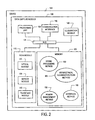
- Fig. 2 illustrates an exemplary data capture module implemented according to an embodiment of the invention.
- Fig. 3 illustrates an exemplary scan module.
- Fig. 4 illustrates another scan module implemented according to another embodiment of the invention.
- Fig. 5 illustrates an exemplary asymmetrical illumination method.
- Fig. 6 illustrates an alternate symmetrical illumination method implemented according to an embodiment of the invention.
- Fig. 7 illustrates an alternate embodiment of the invention comprising an external illumination medium.
- An exemplary data capture device such as, for example, a DPM image scanner, implemented in accordance with the invention comprises an illumination module, for example an LED, positioned on one side of a scan module, for example, the camera, of the scanner. The position of the LED relative to the camera creates asymmetrical narrow-beam illumination for scanning DPM surfaces.
- an illumination module for example an LED
- a scan module for example, the camera
- the angular tolerance of the scanner can be broadened by adding multiple lights or groups of lights around the camera.
- the placement of the lights may or may not be symmetrical with respect to the camera.
- each light or group of lights illuminates the dataform in turn.
- the scanner captures and decodes images of the dataform from each illumination angle, and can cease operation when a successful decode is made.
- the angle of the object with respect to the light source and the camera is dynamic since the object is either moving in front of the scanner or the scanner is being moved in front of the object.
- a DPM scanner typically takes multiple images during one decoding attempt since the angle of the object may be changing and the image captured at certain illumination angles may be easier to decode.
- multiple symmetrical light sources are used to simultaneously illuminate a dataform, it can be difficult to frame the dataform to obtain one highlight and/or shadow per impact site, because there are numerous illumination angles where the multiple simultaneous light sources create multiple highlights and shadows in the captured image.
- the crater and rim of each impact site may create two sets of highlights and shadows, but the image is limited to those two sets. If illuminated symmetrically, the image can include additional highlights and shadows that make interpretation even more difficult. Thus, asymmetrically illuminating the DPM dataform increases the chances of capturing an image that shows one highlight and/or shadow per impact site, making the image easier to decode.
- data capture can be accomplished using a system comprising a data capture module and an external illumination medium.
- a DPM scanner's performance can be improved with the correct illumination, such as on-axis, off axis, asymmetrical, point or diffuse illumination, and the correct illumination can vary under different conditions and/or configurations. If a object's orientation is relatively constant with respect to the data capture module and the external illumination medium, such as, for example, objects on an assembly line, the external illumination medium best suited for the particular set of conditions can be chosen to be directed at the passing objects so that it correctly illuminates dataforms.
- the device 101 can be, in an exemplary embodiment, a hands-free scanner, a handheld scanner, a mobile computer, etc.
- the data collection module 100 can be, in one non-limiting exemplary embodiment, an image scanner module 100.
- the image scanner 100 can be integrated into the device 101.
- the data capture module 100 is illustrated as being within device 101, in alternate embodiments, the data capture module 100 can be a separate module that is coupled to the device 101, by a wire or wirelessly.
- the data capture module 100 can be a convertible handheld/stationary scan gun coupled to a computer 101.
- Image scanner 100 comprises processing unit 105, scan module 115, memory 120, communication interface 110 and illumination module 140 coupled together by bus 125.
- the modules of data capture module 100 can be implemented as any combination of software, hardware, hardware emulating software, and reprogrammable hardware.
- the bus 125 is an exemplary bus showing the interoperability of the different modules of the invention. As a matter of design choice there may be more than one bus and in some embodiments certain modules may be directly coupled instead of coupled to a bus 125.
- Processing unit 105 can be implemented as, in exemplary embodiments, one or more Central Processing Units (CPU), Field-Programmable Gate Arrays (FPGA), etc.
- the processing unit 105 can comprise a general purpose CPU that processes software and raw image data stored in memory 120.
- modules of the processing unit 105 may be preprogrammed in the processing unit's 105 memory to perform functions, such as, for example, signal processing, interface emulation, etc.
- one or more modules of processing unit 105 can be implemented as an FPGA that can be loaded with different processes, for example, from memory 120, and perform a plurality of functions.
- Processing unit 105 can comprise any combination of the processors described above.
- Scan module 115 can be implemented as, in one exemplary embodiment, a camera 115 comprising an optical module 130, a sensor module 135 and a targeting module 142.
- the optical module 130 can be, for example, the lens 130 of the camera 115.
- the optical module 130 can comprise of more than one lens and/or provide more than one focus point.
- the optical module 130 is not limited to lenses; any prism and/or other optical medium that is suitable for capturing images can be used to implement the optical module 130.
- the sensor module 135 can be implemented, in one exemplary embodiment, as a Charged-Coupled Device (CCD).
- CCD Charged-Coupled Device
- the CCD 135 records images in digital format for processing.
- any sensor that captures images can be used to implement the sensor module135, such as, for example, CMOS semiconductors.
- the illumination module 140 may be implemented, in one non-limiting exemplary embodiment, as one or more Light Emitting Diodes (LED) 145. Other illumination mediums may be used in alternate embodiments. The placement, number and use of the illumination medium 140 to provide asymmetric illumination are further described below.
- the targeting module 142 comprises a light source or sources, for example, a laser, that projects a target approximating the field of view of the image scanner 100.
- the target appears on an object as a crosshair, a square, a circle, or any other design that can assist the user in placing the dataform in the field of view of the scanner.
- Memory 120 can be implemented as volatile memory, non-volatile memory and rewriteable memory, such as, for example, Random Access Memory (RAM), Read Only Memory (ROM) and/or flash memory.
- RAM Random Access Memory
- ROM Read Only Memory
- the memory 120 stores methods and processes used to operate the image scanner 100, such as, signal processing method 150, power management method 155, interface method 160 and asymmetrical illumination scan method 165.
- the memory 120 can also be used to store raw image data and/or processed image data.
- the scanner 100 When a decoding operation is initiated, for example a trigger is depressed, the scanner 100 begins asymmetrical illumination scan method 165.
- the scanner illuminates the target dataform from one side of the scan module 115.
- Scan module 115 capture images within the field of view of the scanner 100, and the images are analyzed and decoded by signal processing method 150.
- Fig. 3 illustrates the front view of an exemplary scan module 300.
- Scan module 300 comprises a camera lens 305, an illumination medium 310 and a targeting lens 315.
- the illumination medium 310 for example LED 310, is located on the left side of the camera lens 305. Since the light from the LED 310 is coming from one side of the camera lens 305, LED 310 asymmetrically illuminates dataforms, during a decoding operation.
- Illumination module 310 may comprise a group of LEDs located on the same side of the camera lens 305.
- the LED 310 is positioned to illuminate a target dataform at an angle when the lens 305 is lined up with the dataform. The light from the LED 310 illuminates the dataform at an angle, but the illumination medium and/or scanner does not have to be touching or extremely close to the dataform.
- the scan module 100 comprises additional LEDs 140 located on different sides of the camera lens 130. Since the orientation of the object and the scanner are dynamic, the highlights and/or shadows created by the dataform may be easier to decode from one illumination angle over another.
- the dispersed LEDs used in turn, allow the scanner 100 to asymmetrically illuminate the dataform from different angles. One or more images of the dataform are captured for each illumination angle, and once the dataform is successfully decoded the scanner 100 can end the decoding operation.
- Fig. 4 illustrates the front view of another exemplary scan module 400, implemented in accordance with the invention.
- Scan modules 300 and 400 are illustrative and are not drawn to scale.
- Scan module 400 comprises a camera lens 405, a targeting lens 410, a first illumination medium 415, which comprises a group of LEDs 420, 425 and a second illumination medium 430, which comprises a second group of LEDs 435, 440.
- the scan module 400 captures and analyzes one or more images of a target dataform using the first illumination medium 415. If the scanner 100 does not successfully decode the dataform using the captured images, the scan module 400 illuminates the dataform using the second illumination medium 430, and captures and analyzes additional images.
- a decoding operation performed using the second illumination angle may be successful because the dataform and/or scanner 100 may be positioned so that the second illumination angle produces images that are easier to decode.
- the exemplary embodiment illustrated in Fig. 4 is not limited to two illumination mediums.
- a plurality of LEDs or groups of LEDs can be placed around the camera lens.
- the illumination mediums do not have to be located symmetrically with respect to the camera lens 405. They can be located at different distances from the camera lens 405 to vary the illumination angles.
- the angular tolerance of the scanner 100 can be increased by using a rotating or pivoting illumination medium 140.
- the scanner 100 takes one or more images of the dataform at each illumination angle and optionally stops decoding when the dataform is successfully read.
- the data collection module 100 can be implemented as a module for different devices 101 that communicate in a variety of languages. Therefore, data collection module 100 comprises an interface method 160 that translates the decoded dataform into the language of the device 101 that interfaces with the data collection module 100.
- interfaces include Universal Serial Bus (USB), scanner emulation, IBM keyboard wedge, Symbol Serial Interface (SSI), etc.
- Power management method 155 manages the power used by scanner 100.
- the scanner 100 can switch to a power save mode, when no activity is detected for a given amount of time.
- the power save mode can completely shut down the scanner 100 or alternatively, it can slow the image capture rate, or initiate other power saving techniques.
- Fig. 2 illustrates signal processing method 150, asymmetrical illumination scan method 165, interface method 160 and power management method 155 as separate components, but these methods are not limited to this configuration.
- Each method described herein in whole or in part can be separate components or can interoperate and share operations.
- the methods are depicted in the memory 120, in alternate embodiments the methods can be incorporated permanently or dynamically in the memory of processing unit 105.
- scan module 115 can be separate from the data capture module 100, and the data capture module 100 can be implemented using a general purpose computer and software.
- Memory 120 is illustrated as a single module in Fig. 2 , but in some embodiments image scanner 100 can comprise more than one memory module. For example, the methods described above can be stored in separate memory modules.
- Fig. 5 illustrates an exemplary method 500 for scanning dataforms using asymmetrical illumination.
- Reference to image scanner 100 is made in the description of method 500.
- the steps of method 500 and other methods described herein are exemplary and the order of the steps may be rearranged as a matter of design choice.
- Asymmetrical illumination scan method 500 begins with start step 205.
- the method 500 begins when the image scanner 100 and/or device 101 receives power and/or when a trigger or button on the scanner 100 is pressed.
- the device 101 and/or scanner 100 can run diagnostics prior to operation.
- step 510 the scanner 100 illuminates a target dataform from on side of a scan module.
- the scan module 300 of Fig. 3 illustrates an exemplary configuration having an illumination medium 310 located on one side of the scan module 300. Illumination from one side of the scan module 300 asymmetrically illuminates the target dataform.
- step 510 Processing proceeds from step 510 to step 515, where the scanner 100 captures a representation, for example a digital image, of the target dataform. Then, in step 520, the captured image is analyzed and the target dataform is decoded. In step 545, if the decoding algorithm is successful, processing proceeds to step 555, where the decoded data is further processed.
- the data can be translated into a language that the device 101 can interpret. For example, if the image scanner 100 is attached to a computer via a USB connection, the decoded dataform is translated into a serial form, in step 555, and communicated to the device 101 through communication interface 110.
- processing of method 500 proceeds to step 560 where the method 500 returns to step 505, and the image scanner 100 is ready to process another dataform.
- step 545 if the scanner 100 does not successfully decode the target dataform, processing proceeds to step 550.
- the image scanner 100 does nothing, and returns in step 560 to step 505, but in other examples the scanner 100 can transmit a fail signal to the communication interface 110, and/or emit an audible fail indicator to the scanner 100 operator.
- the device 101 can be programmed to recognize the fail signal and alert the operator of the failure through an audible sound, and/or a message on a screen. Additionally, the scanner 100 and/or device 101 can instruct the operator to hold the dataform up to the scanner 100 and/or angle the scanner and/or object in different directions.
- the scanner 100 in response to a failed decoding attempt, the scanner 100 returns, in step 560, to step 510 and takes another picture of the target dataform for analysis.
- the scanner 100 can try a predetermined number of times before failing. In other examples, two or more images may be analyzed in parallel.
- the scanner 100 can comprise two or more illumination modules.
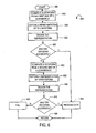
- Fig. 6 illustrate an exemplary embodiment of an asymmetrical illumination scan method 600, where the scanner 100 comprises a scan module with two illumination modules located to the left and right of a camera lens.
- Asymmetrical illumination scan method 600 starts in step 605 where the scanner 100 is triggered into operation and/or receives power.
- the scanner 100 illuminates the target dataform using a first illumination module, for example illumination module one 415.
- method 600 can start with illumination module two 430, or the scanner 100 can alternate between the illumination modules for every decoding operation.
- step 610 Processing proceeds from step 610 to step 615, where the scanner captures a digital representation of the dataform, and in step 620 the image is decoded. If the decoding is successful, processing proceeds from step 625 to step 655, where the decoded data is further processed. Then, in step 660, the scanner 100 returns to start step 605, and is ready for another dataform.
- step 625 if the decoding of the captured image is not successful, processing proceeds from step 625 to step 630, where the scanner 100 illuminates the target dataform from a second side, for example, illumination module two 430, of the scan module 400.
- step 635 an image of the illuminated dataform is captured and in step 640 the image is decoded.
- step 645 if the decoding is successful, processing proceeds from step 645 to step 655, where the decoded data is further processed. Then, in step 660, the scanner 100 returns to start step 605, and is ready for another dataform.
- step 645 if the captured image is not successfully decoded, processing proceeds to fail step 650.
- step 650 in some embodiments method 600 returns, in step 660, to step 610 and attempts to decode the dataform again. This loop can be repeated for a predetermined number of iterations or until the scanner successfully decodes the dataform. In other embodiments, the scanner 100 returns, in step 660 to start step 605.
- the scanner 100 can capture images and attempt to decode the target dataform using the same illumination module for a predetermined number of times before switching to another illumination module.
- Fig. 7 illustrates an alternate embodiment of the invention comprising a data capture system 700 with an external illumination medium.
- Data capture system 700 comprises a data capture module 705 and an illumination medium 710 directed at a object 715.
- the object 715 comprises a DPM dataform, for example, a two dimensional code.
- the data capture system 700 is coupled to a structure 720 that is part of an assembly line. Objects are illuminated by illumination medium 710 as they pass the field of view of the data capture module 705.
- the data capture module 705 captures and analyzes the dataforms on the passing objects 715.
- the data capture system 700 may comprise a structure 720 comprising a base or a platform, where objects can be placed for analysis.
- the data capture module 705 is implemented using a DPM scanner 705 without an illumination medium.
- Dataforms are illuminated by external illumination medium 710.
- the external illumination medium 710 can be implemented as a continuous mode fluorescent light-box, a flash illumination light box powered by LEDs, flash lamps, etc.
- the external illumination is chosen and positioned, manually and/or automatically to optimally illuminate DPM dataforms that pass the field of view of the scanner 705.
- the illumination medium chosen can be point or diffuse illumination and the illumination medium 710 can be positioned asymmetrically, on-axis, off-axis, etc.
- the data capture system 700 comprises multiple illumination mediums and performs the asymmetrical illumination scan method as described in Fig. 6 .
- the scanner 705 in order to facilitate synchronous illumination, is coupled to the illumination medium 710, either by wire, wirelessly, through another computer, etc.
- the scanner 705 can transmit a control signal that turns on the external illumination medium 710 when the scanner 705 takes an image.
- the scanner's 705 exposure setting can be slightly longer than the illumination control signal, so that a delay in the illumination control signal does not cause the illumination medium 710 to be activated outside an exposure period. Turning the illumination medium on and off creates a flashing effect that freezes dataforms on moving objects.
- Commonly available sensors be it CCD or CMOS sensors, often are designed to operate optimally at 25-30 frames per second, according to the prevailing television signal standards around the world. Flash illuminations repeated at these rates tend to exhibit the effect of flicker. But for an environment like that of a constantly moving assembly line, repeated scanning at the maximum allowed rate is sometimes desirable.
- a method to suppress the flicker effect is to cause the illumination module to produce more flashes than that required by the number of image captures by the data capture module.
Landscapes
- Physics & Mathematics (AREA)
- Engineering & Computer Science (AREA)
- General Physics & Mathematics (AREA)
- Theoretical Computer Science (AREA)
- Electromagnetism (AREA)
- Health & Medical Sciences (AREA)
- General Health & Medical Sciences (AREA)
- Toxicology (AREA)
- Artificial Intelligence (AREA)
- Computer Vision & Pattern Recognition (AREA)
- Image Input (AREA)
- Character Input (AREA)
Abstract
Claims (21)
- Procédé d'éclairage asymétrique comportant les étapes consistant à :éclairer (610) un objet en utilisant des premiers moyens d'éclairage à faisceau étroit situés sur une première partie d'un module optique d'un module de capture d'informations,capturer (615) une première représentation électronique dudit objet créée par l'éclairage des premiers moyens d'éclairage à faisceau étroit,décoder (620) la première représentation électronique dudit objet,si le décodage n'est pas réussi, éclairer (630) ledit objet en utilisant des seconds moyens d'éclairage à faisceau étroit situés sur une seconde partie dudit module optique, dans lequel l'éclairage à partir des premiers et seconds moyens d'éclairage à faisceau étroit est sensiblement à la même longueur d'onde, dans lequel l'éclairage à partir des seconds moyens d'éclairage à faisceau étroit éclaire l'objet à partir d'un angle différent comparé à l'éclairage à partir des premiers moyens d'éclairage à faisceau étroit,capturer (635) une seconde représentation électronique dudit objet créée par l'éclairage des seconds moyens d'éclairage à faisceau étroit, etdécoder (640) la seconde représentation électronique dudit objet.
- Procédé selon la revendication 1, dans lequel ledit objet comporte une forme de données bidimensionnelle marquée de manière ponctuelle.
- Procédé selon la revendication 1, dans lequel au moins un desdits moyens d'éclairage est mis en oeuvre sous la forme d'une diode électroluminescente (145).
- Procédé selon la revendication 1, dans lequel ledit module de capture d'informations est un scanner d'image (100).
- Procédé selon la revendication 4, dans lequel ledit scanner d'image comporte une unité de traitement (105), une mémoire (120) et un module de balayage (115).
- Procédé selon la revendication 5, dans lequel ledit module de balayage (115) est une caméra comportant ledit module optique (130), un module de détection (135) et lesdits moyens d'éclairage (415, 430).
- Procédé selon la revendication 6, dans lequel ledit module optique (130) est l'objectif de ladite caméra.
- Procédé selon la revendication 1, dans lequel ledit éclairage dudit objet en utilisant lesdits seconds moyens d'éclairage (430), la capture (635) de la seconde représentation électronique dudit objet et l'analyse de ladite seconde représentation électronique dudit objet sont dépendants du décodage de ladite première représentation électronique dudit objet.
- Procédé selon la revendication 1, dans lequel ledit module de capture d'informations comporte une pluralité supplémentaire de moyens d'éclairage positionnés autour dudit module optique (130).
- Procédé selon la revendication 9, comportant en outre les étapes consistant à :éclairer alternativement chaque moyen d'éclairage de ladite pluralité de moyens d'éclairage (415, 430),capturer des représentations électroniques supplémentaires dudit objet en utilisant chaque éclairage, etanalyser lesdites représentations électroniques supplémentaires capturées dudit objet.
- Procédé selon la revendication 10, dans lequel la capture de représentations électroniques supplémentaires à partir dudit objet s'arrête après un décodage réussi.
- Dispositif de capture d'informations comportant :une unité de traitement (105),un module de balayage (115),des premiers moyens d'éclairage à faisceau étroit (415) situés dans une première position,des seconds moyens d'éclairage à faisceau étroit (430) situés dans une seconde position, etune mémoire (120) stockant au moins un processus qui est opérationnel sur ledit dispositif de capture d'informations, comportant les étapes consistant à :éclairer un objet (715) en utilisant les premiers moyens d'éclairage à faisceau étroit (415),capturer une première représentation électronique dudit objet (715) créée par l'éclairage des premiers moyens d'éclairage à faisceau étroit (415),décoder la première représentation électronique dudit objet (715),si le décodage n'est pas réussi, éclairer l'objet (715) en utilisant les seconds moyens d'éclairage à faisceau étroit (430), dans lequel l'éclairage à partir des premiers et seconds moyens d'éclairage à faisceau étroit (415, 430) est sensiblement à la même longueur d'onde, dans lequel l'éclairage à partir des seconds moyens d'éclairage à faisceau étroit (430) éclaire l'objet à partir d'un angle différent comparé à l'éclairage à partir des premiers moyens d'éclairage à faisceau étroit (415),capturer une seconde représentation électronique dudit objet (715) créée par l'éclairage des seconds moyens d'éclairage à faisceau étroit, etdécoder la seconde représentation.
- Dispositif de capture d'informations selon la revendication 12, dans lequel ledit objet (715) comporte une forme de données bidimensionnelle marquée de manière ponctuelle.
- Dispositif de capture d'informations selon la revendication 12, dans lequel au moins un desdits moyens d'éclairage (415, 430) est mis en oeuvre sous la forme d'une diode électroluminescente (145).
- Dispositif de capture d'informations selon la revendication 12, dans lequel ledit dispositif de capture d'informations est un scanner d'image (100).
- Dispositif de capture d'informations selon la revendication 12, dans lequel ledit module de balayage (115) est une caméra comportant un module optique (130), un module de détection (135) et lesdits moyens d'éclairage (415, 430).
- Dispositif de capture d'informations selon la revendication 16, dans lequel ledit module optique (130) est l'objectif de ladite caméra.
- Dispositif de capture d'informations selon la revendication 12, dans lequel ledit éclairage dudit objet (715) en utilisant lesdits seconds moyens d'éclairage (430), la capture d'une seconde représentation électronique dudit objet (715) et l'analyse de ladite seconde représentation électronique dudit objet (715) sont dépendants d'un décodage de ladite première représentation électronique dudit objet (715).
- Dispositif de capture d'informations selon la revendication 12, comportant en outre une pluralité de moyens d'éclairage supplémentaires positionnés autour dudit module optique (130).
- Dispositif de capture d'informations selon la revendication 19, dans lequel ledit au moins un processus comporte en outre les étapes consistant à :éclairer alternativement chaque moyen d'éclairage de ladite pluralité de moyens d'éclairage supplémentaires (415, 430),capturer des représentations électroniques supplémentaires dudit objet (715) en utilisant chaque éclairage, etanalyser lesdites représentations électroniques supplémentaires capturées dudit objet (715).
- Dispositif de capture d'informations selon la revendication 20, dans lequel la capture de représentations électroniques supplémentaires à analyser à partir dudit objet (715) s'arrête après un décodage réussi.
Applications Claiming Priority (2)
| Application Number | Priority Date | Filing Date | Title |
|---|---|---|---|
| US11/027,733 US7281662B2 (en) | 2004-12-30 | 2004-12-30 | Methods and apparatus for information capture illumination |
| PCT/US2005/044223 WO2006073660A2 (fr) | 2004-12-30 | 2005-12-06 | Procedes et appareil pour l'eclairage de capture d'information |
Publications (3)
| Publication Number | Publication Date |
|---|---|
| EP1831816A2 EP1831816A2 (fr) | 2007-09-12 |
| EP1831816A4 EP1831816A4 (fr) | 2009-12-02 |
| EP1831816B1 true EP1831816B1 (fr) | 2012-07-25 |
Family
ID=36639246
Family Applications (1)
| Application Number | Title | Priority Date | Filing Date |
|---|---|---|---|
| EP05853210A Expired - Lifetime EP1831816B1 (fr) | 2004-12-30 | 2005-12-06 | Procedes et appareil pour l'eclairage de capture d'information |
Country Status (5)
| Country | Link |
|---|---|
| US (2) | US7281662B2 (fr) |
| EP (1) | EP1831816B1 (fr) |
| JP (1) | JP4589409B2 (fr) |
| CN (1) | CN101095147B (fr) |
| WO (1) | WO2006073660A2 (fr) |
Families Citing this family (15)
| Publication number | Priority date | Publication date | Assignee | Title |
|---|---|---|---|---|
| US20030222147A1 (en) * | 2002-06-04 | 2003-12-04 | Hand Held Products, Inc. | Optical reader having a plurality of imaging modules |
| US8403225B2 (en) * | 2006-11-17 | 2013-03-26 | Hand Held Products, Inc. | Vehicle license plate indicia scanning |
| US8556180B2 (en) * | 2009-10-13 | 2013-10-15 | Marson Technology Co., Ltd. | Multiwavelength barcode reader |
| IT1397388B1 (it) * | 2009-12-29 | 2013-01-10 | Datalogic Mobile S R L | Dispositivo portatile e metodo per la lettura di informazioni codificate |
| US8442297B2 (en) * | 2010-02-23 | 2013-05-14 | Arinc Incorporated | Methods of evaluating the quality of two-dimensional matrix dot-peened marks on objects and mark verification systems |
| US9418270B2 (en) | 2011-01-31 | 2016-08-16 | Hand Held Products, Inc. | Terminal with flicker-corrected aimer and alternating illumination |
| US8602308B2 (en) * | 2011-12-22 | 2013-12-10 | Symbol Technologies, Inc. | Imaging device having light field sensor |
| DE102012018388B4 (de) * | 2012-09-18 | 2014-06-26 | Knapp Ag | Einrichtung zur Erkennung eines Codes auf einem Artikel vorzugsweise am Wareneingang eines Kommissioniersystems |
| CN105225523B (zh) * | 2015-10-15 | 2018-01-02 | 浙江宇视科技有限公司 | 一种车位状态检测方法及装置 |
| US9811705B1 (en) | 2016-05-10 | 2017-11-07 | Datalogic Ip Tech S.R.L. | Illumination system with active element for generating different illumination patterns for a data reader |
| US11481568B1 (en) | 2017-12-29 | 2022-10-25 | Cognex Corporation | Dome illuminator for vision system camera and method for using the same |
| US10628646B1 (en) | 2017-12-29 | 2020-04-21 | Cognex Corporation | Off-axis dual-sensor vision system camera and method for using the same |
| EP4268016A4 (fr) * | 2020-12-23 | 2024-12-11 | Anglo American Steelmaking Coal Pty Ltd | Ensemble de capture d'image |
| US11809949B2 (en) * | 2021-04-30 | 2023-11-07 | Zebra Technologies Corporation | Systems and methods to optimize imaging settings and image capture for a machine vision job |
| US12387452B2 (en) | 2022-10-27 | 2025-08-12 | Hand Held Products, Inc. | Automatic illumination switching for a scanning device using reflections |
Family Cites Families (18)
| Publication number | Priority date | Publication date | Assignee | Title |
|---|---|---|---|---|
| JPS5317454B2 (fr) * | 1973-08-22 | 1978-06-08 | ||
| JPS60144884A (ja) * | 1983-12-31 | 1985-07-31 | Nippon Steel Corp | 打刻印字の検出方法 |
| JPS60207980A (ja) * | 1984-03-31 | 1985-10-19 | Tokinaa Kogaku Kk | 画像取込用装置および方法 |
| JPS6180372A (ja) * | 1984-09-26 | 1986-04-23 | Nippon Steel Corp | 打刻印の検出方法 |
| JPS63126081A (ja) * | 1986-11-14 | 1988-05-30 | Nippon Steel Corp | 打刻印の検出方法 |
| JP2959035B2 (ja) * | 1990-03-26 | 1999-10-06 | オムロン株式会社 | エンボス像読取装置 |
| JPH0562012A (ja) * | 1991-08-30 | 1993-03-12 | Nisca Corp | 凹凸情報の読み取り方法及びその装置 |
| JPH05290213A (ja) * | 1992-04-13 | 1993-11-05 | Hitachi Eng Co Ltd | 画像処理方法及びその装置 |
| US5515452A (en) * | 1992-12-31 | 1996-05-07 | Electroglas, Inc. | Optical character recognition illumination method and system |
| JPH06203206A (ja) * | 1993-01-07 | 1994-07-22 | Oki Electric Ind Co Ltd | カードのイメージ読み取り装置 |
| JPH06266890A (ja) * | 1993-03-17 | 1994-09-22 | Dainippon Printing Co Ltd | エンボス文字認識装置 |
| US5648650A (en) * | 1994-09-07 | 1997-07-15 | Alps Electric Co., Ltd. | Optical bar code reading apparatus with regular reflection detecting circuit |
| JPH09218910A (ja) * | 1996-02-08 | 1997-08-19 | Toshiba Corp | マーキング読み取り方法及び装置 |
| JP3280892B2 (ja) * | 1997-09-30 | 2002-05-13 | 富士通株式会社 | 光走査装置 |
| EP1207489B1 (fr) * | 2000-10-26 | 2009-06-17 | Datalogic S.P.A. | Module laser pour la lecture des codes optiques |
| JP2003022414A (ja) * | 2001-07-06 | 2003-01-24 | Sony Corp | バーコードリーダ |
| NO20023090L (no) * | 2002-06-26 | 2003-12-29 | Tomra Systems Asa | Anordning for gjenkjennelse av beholdere |
| US7028901B2 (en) * | 2003-07-17 | 2006-04-18 | Symbol Technologies, Inc. | System and method for reading and decoding optical codes using multiple color illumination |
-
2004
- 2004-12-30 US US11/027,733 patent/US7281662B2/en not_active Expired - Lifetime
-
2005
- 2005-12-06 WO PCT/US2005/044223 patent/WO2006073660A2/fr not_active Ceased
- 2005-12-06 EP EP05853210A patent/EP1831816B1/fr not_active Expired - Lifetime
- 2005-12-06 CN CN2005800457177A patent/CN101095147B/zh not_active Expired - Lifetime
- 2005-12-06 JP JP2007549403A patent/JP4589409B2/ja not_active Expired - Lifetime
-
2007
- 2007-09-14 US US11/855,285 patent/US7543754B2/en not_active Expired - Lifetime
Also Published As
| Publication number | Publication date |
|---|---|
| JP4589409B2 (ja) | 2010-12-01 |
| US7543754B2 (en) | 2009-06-09 |
| WO2006073660A3 (fr) | 2006-10-05 |
| CN101095147B (zh) | 2010-05-12 |
| CN101095147A (zh) | 2007-12-26 |
| US20060144945A1 (en) | 2006-07-06 |
| JP2008527492A (ja) | 2008-07-24 |
| WO2006073660A2 (fr) | 2006-07-13 |
| EP1831816A2 (fr) | 2007-09-12 |
| US20080000978A1 (en) | 2008-01-03 |
| US7281662B2 (en) | 2007-10-16 |
| EP1831816A4 (fr) | 2009-12-02 |
Similar Documents
| Publication | Publication Date | Title |
|---|---|---|
| US7543754B2 (en) | Methods and apparatus for information capture illumination | |
| US6688523B1 (en) | System for reading optical indicia | |
| US6065678A (en) | Bar code scanner having a focusing system | |
| EP2401699B1 (fr) | Lecteur et procédé d'imagerie à ensemble lampe d'éclairage double fonction | |
| US10489623B1 (en) | Multiple imaging assembly for a reader | |
| US20030168512A1 (en) | Optical reader having position responsive decode launch circuit | |
| EP0980537A1 (fr) | Explorateur optique et lecteur d'images pour la lecture d'images et le decodage d'informations optiques, y compris les symboles en une et deux dimensions a profondeur de champ variable | |
| EP2320350B1 (fr) | Annotation d'images optiques sur un dispositif mobile | |
| CN103218596A (zh) | 具有动态多角度照明系统的条码扫描器及其条码扫描方法 | |
| US7322526B1 (en) | System for reading optical indicia | |
| US20060138234A1 (en) | Methods and apparatus for improving direct part mark scanner performance | |
| US6974085B1 (en) | System for reading optical indicia | |
| US7264168B2 (en) | Asymmetrical scanner | |
| EP2542998B1 (fr) | Terminal de capture de données personnalisable par l'utilisateur et procédé qui permettent une imagerie et un traitement d'une pluralité de données cibles sur une ou plusieurs cibles | |
| US8752767B2 (en) | Illumination system with prism for use in imaging scanner | |
| EP2449504B1 (fr) | Procédé et appareil de définition d'un champ de vision d'éclairage d'un lecteur de codes-barres | |
| US5923022A (en) | Method and apparatus for identifying bar code symbols using reading gates | |
| EP1723576B1 (fr) | Systeme et procede pour la lecture des code optiques imprimes ou affiches sur des surfaces reflechissantes | |
| EP1916557B1 (fr) | Scanner optique et lecteur d'image pour lire des images et décoder des informations optiques comprenant une ou deux symbologies à une profondeur variable de champs | |
| JP2006134160A (ja) | 光学式情報読取装置 | |
| US20250139394A1 (en) | Balancing Decoding Performance and Speed Using One or More Parameters for Decoding Damaged Data Matrix Barcodes |
Legal Events
| Date | Code | Title | Description |
|---|---|---|---|
| PUAI | Public reference made under article 153(3) epc to a published international application that has entered the european phase |
Free format text: ORIGINAL CODE: 0009012 |
|
| 17P | Request for examination filed |
Effective date: 20070626 |
|
| AK | Designated contracting states |
Kind code of ref document: A2 Designated state(s): DE FR GB |
|
| DAX | Request for extension of the european patent (deleted) | ||
| RBV | Designated contracting states (corrected) |
Designated state(s): DE FR GB |
|
| A4 | Supplementary search report drawn up and despatched |
Effective date: 20091102 |
|
| 17Q | First examination report despatched |
Effective date: 20100201 |
|
| GRAP | Despatch of communication of intention to grant a patent |
Free format text: ORIGINAL CODE: EPIDOSNIGR1 |
|
| GRAC | Information related to communication of intention to grant a patent modified |
Free format text: ORIGINAL CODE: EPIDOSCIGR1 |
|
| GRAS | Grant fee paid |
Free format text: ORIGINAL CODE: EPIDOSNIGR3 |
|
| GRAA | (expected) grant |
Free format text: ORIGINAL CODE: 0009210 |
|
| AK | Designated contracting states |
Kind code of ref document: B1 Designated state(s): DE FR GB |
|
| REG | Reference to a national code |
Ref country code: GB Ref legal event code: FG4D |
|
| REG | Reference to a national code |
Ref country code: DE Ref legal event code: R081 Ref document number: 602005035319 Country of ref document: DE Owner name: SYMBOL TECHNOLOGIES, LLC (N.D. GES. D. STAATES, US Free format text: FORMER OWNER: SYMBOL TECHNOLOGIES, INC., HOLTSVILLE, N.Y., US |
|
| REG | Reference to a national code |
Ref country code: DE Ref legal event code: R096 Ref document number: 602005035319 Country of ref document: DE Effective date: 20120920 |
|
| PLBE | No opposition filed within time limit |
Free format text: ORIGINAL CODE: 0009261 |
|
| STAA | Information on the status of an ep patent application or granted ep patent |
Free format text: STATUS: NO OPPOSITION FILED WITHIN TIME LIMIT |
|
| 26N | No opposition filed |
Effective date: 20130426 |
|
| REG | Reference to a national code |
Ref country code: DE Ref legal event code: R097 Ref document number: 602005035319 Country of ref document: DE Effective date: 20130426 |
|
| REG | Reference to a national code |
Ref country code: FR Ref legal event code: ST Effective date: 20130830 |
|
| PG25 | Lapsed in a contracting state [announced via postgrant information from national office to epo] |
Ref country code: FR Free format text: LAPSE BECAUSE OF NON-PAYMENT OF DUE FEES Effective date: 20130102 |
|
| REG | Reference to a national code |
Ref country code: DE Ref legal event code: R082 Ref document number: 602005035319 Country of ref document: DE Representative=s name: LKGLOBAL | LORENZ & KOPF PARTG MBB PATENTANWAE, DE Ref country code: DE Ref legal event code: R082 Ref document number: 602005035319 Country of ref document: DE Representative=s name: MAIWALD PATENTANWALTSGESELLSCHAFT MBH, DE Ref country code: DE Ref legal event code: R081 Ref document number: 602005035319 Country of ref document: DE Owner name: SYMBOL TECHNOLOGIES, LLC (N.D. GES. D. STAATES, US Free format text: FORMER OWNER: SYMBOL TECHNOLOGIES, INC., HOLTSVILLE, N.Y., US Ref country code: DE Ref legal event code: R082 Ref document number: 602005035319 Country of ref document: DE Representative=s name: KOPF, KORBINIAN, DIPL.-ING.UNIV., MA, DE |
|
| REG | Reference to a national code |
Ref country code: DE Ref legal event code: R082 Ref document number: 602005035319 Country of ref document: DE Representative=s name: LKGLOBAL | LORENZ & KOPF PARTG MBB PATENTANWAE, DE Ref country code: DE Ref legal event code: R082 Ref document number: 602005035319 Country of ref document: DE Representative=s name: KOPF, KORBINIAN, DIPL.-ING.UNIV., MA, DE Ref country code: DE Ref legal event code: R082 Ref document number: 602005035319 Country of ref document: DE Representative=s name: LKGLOBAL LORENZ UND KOPF PATENTANWALT, ATTORNE, DE |
|
| REG | Reference to a national code |
Ref country code: DE Ref legal event code: R082 Ref document number: 602005035319 Country of ref document: DE Representative=s name: LKGLOBAL | LORENZ & KOPF PARTG MBB PATENTANWAE, DE Ref country code: DE Ref legal event code: R082 Ref document number: 602005035319 Country of ref document: DE Representative=s name: LKGLOBAL LORENZ UND KOPF PATENTANWALT, ATTORNE, DE |
|
| P01 | Opt-out of the competence of the unified patent court (upc) registered |
Effective date: 20230416 |
|
| PGFP | Annual fee paid to national office [announced via postgrant information from national office to epo] |
Ref country code: DE Payment date: 20241121 Year of fee payment: 20 |
|
| PGFP | Annual fee paid to national office [announced via postgrant information from national office to epo] |
Ref country code: GB Payment date: 20241122 Year of fee payment: 20 |
|
| REG | Reference to a national code |
Ref country code: DE Ref legal event code: R071 Ref document number: 602005035319 Country of ref document: DE |
|
| REG | Reference to a national code |
Ref country code: GB Ref legal event code: PE20 Expiry date: 20251205 |