EP1832008B1 - Elektrisches haushaltsgerät mit der fähigkeit zu stromleitungskommunikation - Google Patents
Elektrisches haushaltsgerät mit der fähigkeit zu stromleitungskommunikation Download PDFInfo
- Publication number
- EP1832008B1 EP1832008B1 EP05822086.4A EP05822086A EP1832008B1 EP 1832008 B1 EP1832008 B1 EP 1832008B1 EP 05822086 A EP05822086 A EP 05822086A EP 1832008 B1 EP1832008 B1 EP 1832008B1
- Authority
- EP
- European Patent Office
- Prior art keywords
- connector
- home appliance
- power cable
- cable communication
- power
- Prior art date
- Legal status (The legal status is an assumption and is not a legal conclusion. Google has not performed a legal analysis and makes no representation as to the accuracy of the status listed.)
- Expired - Lifetime
Links
Images



Classifications
-
- H—ELECTRICITY
- H04—ELECTRIC COMMUNICATION TECHNIQUE
- H04B—TRANSMISSION
- H04B3/00—Line transmission systems
- H04B3/54—Systems for transmission via power distribution lines
- H04B3/56—Circuits for coupling, blocking, or by-passing of signals
-
- H—ELECTRICITY
- H04—ELECTRIC COMMUNICATION TECHNIQUE
- H04B—TRANSMISSION
- H04B2203/00—Indexing scheme relating to line transmission systems
- H04B2203/54—Aspects of powerline communications not already covered by H04B3/54 and its subgroups
- H04B2203/5429—Applications for powerline communications
- H04B2203/5454—Adapter and plugs
-
- H—ELECTRICITY
- H04—ELECTRIC COMMUNICATION TECHNIQUE
- H04B—TRANSMISSION
- H04B2203/00—Indexing scheme relating to line transmission systems
- H04B2203/54—Aspects of powerline communications not already covered by H04B3/54 and its subgroups
- H04B2203/5429—Applications for powerline communications
- H04B2203/5458—Monitor sensor; Alarm systems
-
- H—ELECTRICITY
- H04—ELECTRIC COMMUNICATION TECHNIQUE
- H04B—TRANSMISSION
- H04B2203/00—Indexing scheme relating to line transmission systems
- H04B2203/54—Aspects of powerline communications not already covered by H04B3/54 and its subgroups
- H04B2203/5462—Systems for power line communications
- H04B2203/5483—Systems for power line communications using coupling circuits
Definitions
- the present invention relates to home appliances, and more particularly, to a home appliance, such as a washing machine or a dryer, which enables a user to make power line communication therewith for monitoring progress thereof, remotely.
- a home appliance such as a washing machine or a dryer
- the home appliance an apparatus for operating by using electricity in a home, converts the electricity into a light, heat, or power, for convenience of a home life.
- the washing machine is installed in a cellar, or separate warehouse, or the like, far from a living space in practice.
- the installation of the washing machine far from a living room where a user stays most of time causes difficulty in knowing progress of the washing machine, such as the present cycle of the washing machine or a time period left, easily.
- the user is liable to fail to notice an error in the cycle of the washing machine, to fail in taking a proper countermeasure, leaving the laundry in contact with detergent and the washing water for a long time to cause decoloring of the laundry, thereby damaging cloth of the laundry itself.
- a remote monitoring system is in need for monitoring the home appliance from a user's desired place.
- US 2002/0140547 A1 discloses an apparatus and method of clock synchronization of a powerline modem network for a plurality of devices.
- the powerline modem permits communication between the plurality of devices over a powerline network.
- US 2004/0111496 A1 discloses a home network system and a method for adding and/or deleting home appliances thereto/therefrom.
- the home network system is constructed so that a plurality of home appliances can transmit and receive data to/from one another.
- a plurality of power line modems are connected respectively to the home appliances to modulate and demodulate data transmitted and received over an internal network by the home appliances.
- EP 1 343 253 A1 discloses a power line communication MODEM including a MODEM main body portion and a power supply portion.
- the object of the present invention designed for solving the problems of the related art, lies on providing a home appliance which enables a user to make power line communication therewith, for easy, and remote monitoring, and control of a state of the home appliance, such as a washing machine, or dryer far from a user, for convenient and effective use of the home appliance.
- a home appliance which enables power cable communication therewith, including a body forming an exterior of the home appliance, a main control unit at the body, for making various kinds of control of the home appliance, and a power cable communication modem at the body, for transmission/reception of various kinds of data to/from a remote monitor which monitors the home appliance remotely.
- a home appliance which enables power cable communication therewith, includes a body forming an exterior of the home appliance, a main control unit at the body, for making various kinds of control of the home appliance, a power cable communication modem at the body, for transmission/ reception of various kinds of data to/from a remote monitor which monitors the home appliance remotely, a line connector connected both to the signal lines of the main control unit and the power line of the home appliance, and a line connection connector at the power cable communication modem for making the power cable communication modem to be connected to the signal lines of the main control unit and the power line of the home appliance at a time as the line connection connector is detachably connected to the line connector.
- a home appliance which enables power cable communication therewith, includes a body forming an exterior of the home appliance, a main control unit at the body, for making various kinds of control of the home appliance, a power cable communication modem at the body, for transmission/ reception of various kinds of data to/from a remote monitor which monitors the home appliance remotely, a line connector connected both to the signal lines of the main control unit and the power line of the home appliance, a line connection connector at the power cable communication modem for making the power cable communication modem to be connected to the signal lines of the main control unit and the power line of the home appliance at a time as the line connection connector is detachably connected to the line connector, and a connector cover for detachable connection to the line connector when the power cable communication modem is not mounted to the line connector for preventing foreign matters from infiltrating into the line connector.
- a home appliance which enables power cable communication therewith, includes a body forming an exterior of the home appliance, a main control unit at the body, for making various kinds of control of the home appliance, a power cable communication modem at the body, for transmission/ reception of various kinds of data to/from a remote monitor which monitors the home appliance remotely, a signal connector connected to the signal lines at the main control unit, a power connector connected to the power line to the home appliance, a signal connection connector at the power cable communication modem for connection to the signal connector, a power source connection connector at the power cable communication modem for connection to the power connector, and a connector cover for detachable connection to the line connector when the power cable communication modem is not mounted to the line connector for preventing foreign matters from infiltrating into the line connector.
- the home appliance which enables power cable communication therewith of the present invention has the following effects.
- the user's easy and remote detection and control of a state of a home appliance is permitted.
- the user can take an appropriate measure at an appropriate time for the home appliance enabling an effective management of the home appliance, such as maintenance of the home appliance.
- a power cable communication modem is mounted on each of home appliances, such as a washing machine 2 and a dryer 3 (hereafter called as home appliances, collectively) in a space (a veranda, or cellar) far from a living room or a bed room for making remote monitoring.
- home appliances such as a washing machine 2 and a dryer 3 (hereafter called as home appliances, collectively) in a space (a veranda, or cellar) far from a living room or a bed room for making remote monitoring.
- a remote monitor 1 provided to a place where a user stays most of the time (i.e., a place the user desires to make the remote monitoring), is connected to each of the power cable communication modems on the home appliances with power cables for transmitting progress of the home appliances to the user.
- the remote monitor 1 has a display circuit board (not shown), and a communication modem (not shown) mounted therein, for transmission/reception of data to/ from the power cable modems on the home appliances, so that the user can monitor progress of the home appliances.
- a home appliance which enables power line communication therewith in accordance with a first preferred embodiment of the present invention will be described with reference to FIG. 2 .
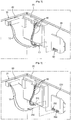
- the home appliance includes a body 10, a main control unit 20, and a power cable communication modem 30.
- the body 10 forms an exterior of the home appliance.
- the main control unit 20 is in the body 10 for making various kinds of control of the home appliance.
- the power cable communication modem 30 is of a built-in type in the body 10, connected to signal lines 60 at the main control unit 20 and a power line for the home appliance for transmission/reception of various data to/from the remote monitor 1 (see FIG. 1 ) that makes remote monitoring of a state of the home appliance.
- the power cable communication modem 30 may be fastened to an inside of the body 10 with fastening members (not shown), or to a separate fixing bracket fixedly secured to the inside of the body 10.
- the signal lines 60 at the main control unit 20 and the power cables 70 for the home appliance are connected to one line connector 40, and the power cable communication modem 30 has a line connection connector 50 for detachable connection of the line connector 40.
- the power cable communication modem 30 is connected both to the main control unit 20 and a power source, at a time.
- the line connector 40 and the line connection connector 50 are detachably connected to each other in shapes of a female terminal and a male terminal of a hook type.
- the line connector 40 and the line connection connector 50 are electrically connected as the female terminal and the male terminal are brought into contact with each other at the moment the line connector 40 and the line connection connector 50 are connected.
- the home appliance further includes a noise filter 80.
- the noise filter 80 has an input terminal connected to an external power line to the home appliance, and an output terminal in the body 10 for connection to the main control unit 20 and the line connector 40.
- the power to the home appliance has the noise removed therefrom as the power passes through the noise filter 80 before being supplied to the main control unit 20 and the power cable communication modem 30.
- the home appliance includes a body 10, a main control unit 20, and a power cable communication modem 230.
- the power cable communication modem 230 also is of a built-in type fastened to an inside of the body only with fastening members (not shown) or with a separate fixing bracket (not shown).
- the power cable communication modem 230 in the home appliance which enables power line communication therewith in accordance with an example useful for understanding the invention is connected to the main control unit 20 and a power source through a signal connector 241, and a power connector 241, and a signal connection connector 251 and a power connection connector 252 corresponding thereto, respectively.
- the signal connector 241 is connected to the signal lines 60 at the main control unit 20, the power connector 242 is connected to the power source line 70 through which a power is supplied, and the power cable communication modem 230 is provided with a signal connection connector 251 and a power connection connector 252 in correspondence to the signal connector 241 and the power connector 242, respectively.
- the power cable communication modem 230 is connected both to the main control unit 20 and the power source, to transmit/receive various data to/from a remote monitor 1 (see FIG. 1 ) that makes remote monitoring of a state of the home appliance.
- the signal connector 241 and the signal connection connector 251, and the power connector 242 and the power source connection connector 252 are detachably connected to each other in a hook type with shapes of a female terminal and a male terminal, respectively.
- the signal connector 241 and the signal connection connector 251, and the power connector 242 and the power source connection connector 252 are electrically connected respectively as the female terminal and the male terminal are engaged with each other, to bring the female terminal and the male terminal in contact with each other.
- the home appliance in accordance with a second embodiment of the present invention also further includes a noise filter 80 for preventing noise of external power source from transmitting to the main control unit 20 and the power cable communication modem 230.
- the noise filter 80 has an input terminal connected to an external power cable to the home appliance, and an output terminal in the body 10 for connection to the main control unit 20 and the power connector 242.
- the power to the home appliance has the noise removed therefrom as the power passes through the noise filter 80 before being supplied to the main control unit 20 and the power cable communication modem 230.
- the home appliance which enables power line communication therewith in accordance with a second preferred embodiment of the present invention includes a body 10, a main control unit 20, and a power cable communication modem 330.
- the body 10 forms an exterior of the home appliance, and the main control unit 20 is in the body 10 for making various kinds of control of the home appliance.
- the power cable communication modem 330 is of an exterior mounting type to be exposed to an outside of the body 10, and connected to signal lines 60 at the main control unit 20 and a power line 70 for the home appliance, for transmission/ reception of various data to/from the remote monitor 1 (see FIG. 1 ) that makes remote monitoring of a state of the home appliance.
- the power cable communication modem 330 may be fastened to an outside of the body 10 with fastening members (not shown), or to a separate fixing bracket (not shown) fixedly secured to the outside of the body 10.
- positioning boss 391 formed on an outside surface of the power cable communication modem 330, or the body 10, and a positioning hole 392 on an opposite side of the positioning boss 391 for joining with the positioning boss 391.
- mounting work of the power cable communication modem 330 can be improved by making the mounting work to pass through a preliminary mounting stage in which the positioning boss 391 is placed in the positioning hole 392 before the power cable communication modem 330 is mounted to the outside surface of the body 10 with the fastening members.
- the signal lines 60 at the main control unit 20 and the power cables 70 for the home appliance are connected to one line connector 340 which is fixedly secured to the body 10 so as to be exposed to an outside of the body 10.
- the power cable communication modem 330 has a line connection connector 350 for detachable connection of the line connector 340.
- the power cable communication modem 330 is connected both to the main control unit 20 and a power source, at a time.
- the line connector 340 and the line connection connector 350 are detachably connected to each other in shapes of a female terminal and a male terminal of a hook type.
- the line connector 340 and the line connection connector 350 are electrically connected as the female terminal and the male terminal are brought into contact with each other at the moment the line connector 340 and the line connection connector 350 are connected.
- the home appliance further includes a noise filter 80.
- the noise filter 80 has an input terminal connected to an external power cable to the home appliance, and an output terminal in the body 10 for connection to the main control unit 20 and the line connector 340.
- the power to the home appliance has the noise removed therefrom as the power passes through the noise filter 80 before being supplied to the main control unit 20 and the power cable communication modem 330.
- the home appliance in accordance with the third preferred embodiment of the present invention is vulnerable to infiltration of foreign matters, such as dust, into the line connector 340 if the power cable communication modem 330 is not mounted thereon.
- the line connector 340 has a connector cover 300 detachably provided thereto when the power cable communication modem 330 in not mounted.
- the connector cover 300 includes a plug portion 301 and a cover portion 302.
- the plug portion 301 is placed in the line connector 340 when the connector cover 300 is mounted to the line connector 340, and the cover portion 302, at rear of the plug portion 301, encloses a circumference of the line connector 340 when the connector cover 300 is mounted to the line connector 340.
- the line connector 340 has hook slots 343a in an inside thereof, and the connector cover 300 includes elastic pieces each having a hook 303a in correspondence to each of the hook slots 343 a.
- the elastic piece 303 on the connector cover 300 includes the hook 303a in correspondence to the hook slot 343a, with an end 303b of the hook 303a extended through a pass through hole in the cover portion 302 so as to be exposed to an outside of the cover portion 302, for enabling handling.
- the connector cover 300 is formed of plastic or synthetic resin.
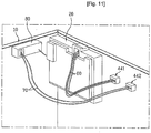
- the home appliance which enables power line communication therewith in accordance with a second example useful for understanding the invention includes a body 10, a main control unit 20, and a power cable communication modem 430.
- the power cable communication modem 430 is also of an exterior mounting type to be fastened to an outside of the body 10 only with fastening members (not shown), or to a separate fixing bracket (not shown).
- positioning boss 391 formed on an outside surface of the power cable communication modem 430, or the body 10, and a positioning hole 392 392 on an opposite side of the positioning boss 391 for joining with the positioning boss 391.
- mounting work of the power cable communication modem 430 can be improved by making the mounting work to pass through a preliminary mounting stage in which the positioning boss 391 is placed in the positioning hole 392 before the power cable communication modem 430 is mounted to the outside surface of the body 10 with the fastening members.
- the body 10 forms an exterior of the home appliance, and the main control unit 20 is in the body 10 for making various kinds of control of the home appliance.
- the power cable communication modem 430 is connected to the main control unit 20 and a power source through a signal connector 441, and a power connector 442, and a signal connection connector 451 and a power connection connector 452 to be connected to the signal connector 441 and the power connector 442, respectively.
- the signal connector 441 is connected to signal lines 60 at the main control unit 20, and the signal connector 441 and the power connector 442 are secured to the body 10 so as to be exposed to an outside of the body 10.
- the power cable communication modem 430 is provided with a signal connection connector 451 and a power source connection connector 452 in correspondence to the signal connector 441 and the power connector 442, respectively.
- the power cable communication modem 430 is connected to the main control unit 20 and the power source at a time, for transmission/ reception of various data to/from the remote monitor 1 (see FIG. 1 ) that makes remote monitoring of a state of the home appliance by a power cable communication system.
- the signal connector 441 and the signal connection connector 451, and the power connector 442 and the power source connection connector 452 are detachably connected to each other in shapes of female terminals and male terminals of a hook type.
- the signal connector 441 and the signal connection connector 451, and the power connector 442 and the power source connection connector 452 are electrically connected as the female terminals and the male terminals are brought into contact with each other at the moment the signal connector 441 and the signal connection connector 451, and the power connector 442 and the power source connection connector 452are connected, respectively.
- the home appliance in accordance with the second example further includes a noise filter 80.
- the noise filter 80 has an input terminal connected to an external power cable to the home appliance, and an output terminal in the body 10 for connection to the main control unit 20 and the power connector 442.
- the power to the home appliance has the noise removed therefrom as the power passes through the noise filter 80 before being supplied to the main control unit 20 and the power cable communication modem 430.
- the home appliance in accordance with the second example is also vulnerable to infiltration of foreign matters, such as dust, into the signal connector 441 and the power connector 442 if the power cable communication modem 430 is not mounted thereon.
- the signal connector 441 and the power connector 442 have connector covers respectively provided thereto when the power cable communication modem 430 in not mounted.
- the connector covers respectively provided to the signal connector 441 and the power connector 442 have shapes identical to a shape of the connector cover 300 in FIGS. 6 to 9 .
- the connector covers are formed of plastic or synthetic resin, with shapes identical to the connector cover 300, and with sizes corresponding to the signal connector 441 and the power connector 442, respectively.
- the home appliance in accordance with the second example can also prevent foreign matters, such as dust, from infiltrating into insides of the signal connector 441 and the power connector 442 in a case the power cable communication modem 430 is not mounted.
- the remote monitor for home appliance of the present invention has significantly high industrial applicability because the remote monitor permits, firstly, the user's easy and remote detection and control of a state of a home appliance, secondly, the user to take an appropriate measure at an appropriate time for the home appliance enabling an effective management of the home appliance, such as maintenance of the home appliance, thirdly, user's effective management of things, such as laundry, cooking objects, and the like, used for the home appliance, fourthly, easy mounting of the power cable communication modem to the home appliance, and fifthly, easy connection of the power cable, and signal lines to the power cable communication modem.
Landscapes
- Engineering & Computer Science (AREA)
- Power Engineering (AREA)
- Computer Networks & Wireless Communication (AREA)
- Signal Processing (AREA)
- Selective Calling Equipment (AREA)
- Cable Transmission Systems, Equalization Of Radio And Reduction Of Echo (AREA)
- Telephonic Communication Services (AREA)
Claims (16)
- Haushaltsgerät, das eine Kommunikation über Stromkabel ermöglicht, und das Folgendes umfasst:einen Körper (10), der eine Außenseite des Haushaltsgeräts bildet;eine Hauptsteuerungseinheit (20) an dem Körper (10), um die Steuerung des Haushaltsgeräts herzustellen; undein Stromkabelkommunikationsmodem (30, 330) an dem Körper (10), um Daten zu einem entfernten Überwachungsgerät (1) zu übertragen bzw. um Daten von einem entfernten Überwachungsgerät (1) zu empfangen, das das Haushaltsgerät aus der Ferne überwacht, dadurch gekennzeichnet, dass:ein Leitungsverbinder (40, 340) sowohl mit den Signalleitungen (60) der Hauptsteuerungseinheit (20) als auch der Stromleitung (70) des Haushaltsgeräts verbunden ist;einen Leitungsanschlussverbinder (50, 350) an dem Stromkabelkommunikationsmodem (30, 330), um das Stromkabelkommunikationsmodem (30, 330) mit den Signalleitungen (60) der Hauptsteuerungseinheit (20) und der Stromleitung (70) des Haushaltsgeräts zu verbinden, wenn der Leitungsanschlussverbinder (50, 350) mit dem Leitungsverbinder (40, 340) lösbar verbunden ist; undeine Verbinderabdeckung (300) für eine lösbare Verbindung mit dem Leitungsverbinder (40, 340), wenn das Stromkabelkommunikationsmodem (30, 330) nicht an den Leitungsverbinder (40, 340) montiert ist, um zu verhindern, dass Fremdstoffe in den Leitungsverbinder (40, 340) eindringen.
- Haushaltsgerät nach Anspruch 1, wobei das Stromkabelkommunikationsmodem (30, 330) mit Signalleitungen (60) der Hauptsteuerungseinheit (20) und einer Stromleitung (70) des Haushaltsgeräts verbunden ist, um Daten zu dem entfernten Überwachungsgerät (1) zu übertragen oder Daten von dem entfernten Überwachungsgerät (1) zu empfangen.
- Haushaltsgerät nach Anspruch 1, wobei der Leitungsverbinder (40, 340) und der Leitungsanschlussverbinder (50, 350) miteinander lösbar in Form eines Buchsenanschlusses und eines Steckeranschlusses des Hakentyps verbunden sind.
- Haushaltsgerät nach Anspruch 1, wobei die Verbinderabdeckung (300) einen Steckabschnitt (301), um in dem Leitungsverbinder (40, 340) positioniert zu werden, und einen Abdeckabschnitt (302) an der Rückseite des Steckabschnitts (301), um einen Umfang des Leitungsverbinders (40, 340) zu umschließen, enthält.
- Haushaltsgerät nach Anspruch 4, wobei der Steckabschnitt (301) einen Haken (303a) zum lösbaren Eingriff in einem Hakenschlitz (343a) in dem Leitungsverbinder (340) und ein Ende (303b) des Hakens (303a) enthält, das sich durch ein Durchgangsloch in dem Abdeckabschnitt (302) erstreckt, um an einer Außenseite des Abdeckabschnitts (302) frei zu liegen, um eine Handhabung zu ermöglichen.
- Haushaltsgerät nach Anspruch 1, wobei die Verbinderabdeckung (300) aus Kunststoff oder Kunstharz gebildet ist.
- Haushaltsgerät nach Anspruch 1, das ferner Folgendes umfasst: einen Signalverbinder, der an der Hauptsteuereinheit (20) mit den Signalleitungen (60) verbunden ist; einen Stromverbinder, der mit der Stromleitung (70) zu dem Haushaltsgerät verbunden ist; einen Signalanschlussverbinder an dem Stromkabelkommunikationsmodem (30, 330) zur Verbindung mit dem Signalverbinder; und einen Stromquellenanschlussverbinder an dem Stromkabelkommunikationsmodem (30, 330) zur Verbindung mit dem Stromverbinder.
- Haushaltsgerät nach Anspruch 7, wobei der Signalverbinder und der Signalanschlussverbinder, der Stromverbinder und der Stromquellenanschlussverbinder jeweils in Form von Buchsenanschlüssen und Steckeranschlüssen des Hakentyps lösbar miteinander verbunden sind.
- Haushaltsgerät nach Anspruch 1, wobei das Stromkabelkommunikationsmodem (30) ein eingebautes Modem ist, das im Inneren des Körpers (10) vorgesehen ist.
- Haushaltsgerät nach Anspruch 9, wobei das Stromkabelkommunikationsmodem (30) mit Befestigungselementen an einer Innenfläche des Körpers (10) fest angebracht ist.
- Haushaltsgerät nach Anspruch 9, wobei das Stromkabelkommunikationsmodem (30) an einer Befestigungsklammer an einer Innenfläche des Körpers (10) fest angebracht ist.
- Haushaltsgerät nach Anspruch 1, wobei das Stromkabelkommunikationsmodem (330) von einem äußeren Montagetyp ist, um an einer Außenseite des Körpers (10) frei zu liegen.
- Haushaltsgerät nach Anspruch 12, wobei das Stromkabelkommunikationsmodem (330) mit Befestigungselementen an einer Außenfläche des Körpers (10) fest angebracht ist.
- Haushaltsgerät nach Anspruch 12, wobei das Stromkabelkommunikationsmodem (330) oder der Körper (10) einen Positionierungsvorsprung (391) enthält, und das andere des Stromkabelkommunikationsmodems (330) oder des Körpers (10) eine Positionierungsöffnung (392) enthält, die dem Positionierungsvorsprung (391) gegenüberliegt, um den Positionierungsvorsprung (391) darin zu positionieren.
- Haushaltsgerät nach Anspruch 1, das ferner in dem Körper (10) ein Rauschfilter (80) umfasst, um zu verhindern, dass ein Rauschen einer Stromquelle zu der Hauptsteuerungseinheit (20) und dem Stromkabelkommunikationsmodem (30, 330) übertragen wird.
- Haushaltsgerät nach Anspruch 1, wobei das Rauschfilter (80) einen Eingangsanschluss, der mit einer äußeren Stromleitung zu dem Haushaltsgerät verbunden ist, und einen Ausgangsanschluss, der mit der Hauptsteuerungseinheit (20) und dem Stromkabelkommunikationsmodem (30, 330) verbunden ist, aufweist.
Applications Claiming Priority (4)
| Application Number | Priority Date | Filing Date | Title |
|---|---|---|---|
| KR1020040116090A KR20060077277A (ko) | 2004-12-30 | 2004-12-30 | 가전기기의 원격 모니터링을 위한 전력선 통신용 모뎀의설치 구조 |
| KR1020040116088A KR101100187B1 (ko) | 2004-12-30 | 2004-12-30 | 가전기기의 원격 모니터링을 위한 전력선 통신용 모뎀의설치 구조 |
| KR1020040116089A KR101100188B1 (ko) | 2004-12-30 | 2004-12-30 | 가전기기 |
| PCT/KR2005/004435 WO2006071020A1 (en) | 2004-12-30 | 2005-12-21 | A electric home appliance able to power line communication |
Publications (3)
| Publication Number | Publication Date |
|---|---|
| EP1832008A1 EP1832008A1 (de) | 2007-09-12 |
| EP1832008A4 EP1832008A4 (de) | 2014-01-01 |
| EP1832008B1 true EP1832008B1 (de) | 2017-09-06 |
Family
ID=36615109
Family Applications (1)
| Application Number | Title | Priority Date | Filing Date |
|---|---|---|---|
| EP05822086.4A Expired - Lifetime EP1832008B1 (de) | 2004-12-30 | 2005-12-21 | Elektrisches haushaltsgerät mit der fähigkeit zu stromleitungskommunikation |
Country Status (5)
| Country | Link |
|---|---|
| US (1) | US20070279197A1 (de) |
| EP (1) | EP1832008B1 (de) |
| JP (1) | JP2008527781A (de) |
| AU (1) | AU2005320475B2 (de) |
| WO (1) | WO2006071020A1 (de) |
Families Citing this family (2)
| Publication number | Priority date | Publication date | Assignee | Title |
|---|---|---|---|---|
| CN102833308A (zh) * | 2012-06-12 | 2012-12-19 | 王坤 | 基于电力线载波局域网的远程监控系统节点 |
| CN102799119A (zh) * | 2012-07-25 | 2012-11-28 | 广东志高空调有限公司 | 一种洗衣设备和系统 |
Family Cites Families (15)
| Publication number | Priority date | Publication date | Assignee | Title |
|---|---|---|---|---|
| US4731032A (en) * | 1986-04-09 | 1988-03-15 | Thomas & Betts Corporation | Protective cover for electrical connector |
| JPH0817540B2 (ja) * | 1986-11-12 | 1996-02-21 | 株式会社日立製作所 | 家庭電化機器の集中制御装置 |
| US5185881A (en) * | 1990-09-12 | 1993-02-09 | Marcraft International Corporation | User repairable personal computer |
| JP2530841Y2 (ja) * | 1992-03-24 | 1997-04-02 | 矢崎総業株式会社 | カバー付コネクタ |
| CA2265820A1 (en) * | 1996-09-18 | 1998-03-26 | Craig S. Wood | Gps power/data cable system |
| JPH1118167A (ja) * | 1997-06-19 | 1999-01-22 | Zojirushi Corp | 生活モニターシステム |
| US5860826A (en) * | 1997-08-25 | 1999-01-19 | Chang; Warren | Electric connector fastener |
| US6754855B1 (en) * | 1999-12-01 | 2004-06-22 | Microsoft Corporation | Automated recovery of computer appliances |
| EP1217475B1 (de) * | 2000-12-13 | 2005-10-26 | Lg Electronics Inc. | Vorrichtung und Verfahren zur Abstandssteuerung von Haushaltsgeräten |
| US6577231B2 (en) * | 2001-04-03 | 2003-06-10 | Thomson Licensing Sa | Clock synchronization over a powerline modem network for multiple devices |
| JP2003258690A (ja) | 2002-03-05 | 2003-09-12 | Alps Electric Co Ltd | 電力搬送用モデム |
| KR100505230B1 (ko) * | 2002-12-10 | 2005-08-03 | 엘지전자 주식회사 | 홈네트워크 시스템 및 그 제품 삭제방법 |
| US20040171288A1 (en) * | 2003-02-28 | 2004-09-02 | Tyco Electronics Corporation | Apparatus, articles of manufacture and method for a wire dress cover assembly |
| US6995658B2 (en) * | 2003-06-11 | 2006-02-07 | The Boeing Company | Digital communication over 28VDC power line |
| TWM250335U (en) * | 2003-09-22 | 2004-11-11 | Exon Science Inc | Cable end connector |
-
2005
- 2005-12-21 US US10/593,618 patent/US20070279197A1/en not_active Abandoned
- 2005-12-21 AU AU2005320475A patent/AU2005320475B2/en not_active Ceased
- 2005-12-21 EP EP05822086.4A patent/EP1832008B1/de not_active Expired - Lifetime
- 2005-12-21 JP JP2007549243A patent/JP2008527781A/ja active Pending
- 2005-12-21 WO PCT/KR2005/004435 patent/WO2006071020A1/en not_active Ceased
Non-Patent Citations (1)
| Title |
|---|
| None * |
Also Published As
| Publication number | Publication date |
|---|---|
| AU2005320475A1 (en) | 2006-07-06 |
| EP1832008A4 (de) | 2014-01-01 |
| JP2008527781A (ja) | 2008-07-24 |
| WO2006071020A1 (en) | 2006-07-06 |
| EP1832008A1 (de) | 2007-09-12 |
| AU2005320475B2 (en) | 2009-04-09 |
| US20070279197A1 (en) | 2007-12-06 |
Similar Documents
| Publication | Publication Date | Title |
|---|---|---|
| EP1309747B1 (de) | Waschmaschine mit vorrichtung zum datenaustausch zu/von einer externen vorrichtung | |
| AU2001278798A1 (en) | Washing machine with device for data exchange to/from external device | |
| US8130510B2 (en) | Printed circuit board assembly of electronic appliance | |
| CN106299904A (zh) | 线缆结构、电源线结构和电器设备 | |
| CN206076634U (zh) | 电源线插头、电源线结构和电器设备 | |
| WO2007086633A2 (en) | Remote controlling system, device and methods for electric device | |
| US20070279197A1 (en) | Electric Home Appliance Able To Power Line Communication | |
| KR100792067B1 (ko) | 전기 기기 원격제어 시스템 | |
| JPH10248164A (ja) | 使用電力検出制御システムおよびコンセント用アダプタ | |
| JPH08223092A (ja) | ロードサーベイシステム | |
| CN203589257U (zh) | 一种带有信息传输功能的智能插座和智能插头 | |
| KR101100188B1 (ko) | 가전기기 | |
| CN101095292A (zh) | 能够进行电力线通信的家用电器 | |
| KR101100187B1 (ko) | 가전기기의 원격 모니터링을 위한 전력선 통신용 모뎀의설치 구조 | |
| CN218304550U (zh) | 供电座、加热组件、暖奶器及水杯 | |
| TWI647891B (zh) | Remote remote power connector | |
| CN206196168U (zh) | 通信装置、电源线结构和电器设备 | |
| CN212908381U (zh) | 模块化漏电保护器及模块化智能漏电保护插座 | |
| US20020137388A1 (en) | Power adapter and the power cord take-up device thereof | |
| KR20150113058A (ko) | 통신 모듈 어댑터 | |
| US20110035074A1 (en) | Remote controlled power consuming device and module therefore | |
| KR20160057275A (ko) | 박스탭 외부 제어 시스템 | |
| CN220492281U (zh) | 一种家用电器电源线和插座固定结构 | |
| CN101909506A (zh) | 用于使用水的器具的多功能转换器 | |
| JP2004228923A (ja) | ホームネットワーク型電気機器、通信アダプタおよびホームネットワークシステム |
Legal Events
| Date | Code | Title | Description |
|---|---|---|---|
| PUAI | Public reference made under article 153(3) epc to a published international application that has entered the european phase |
Free format text: ORIGINAL CODE: 0009012 |
|
| 17P | Request for examination filed |
Effective date: 20070627 |
|
| AK | Designated contracting states |
Kind code of ref document: A1 Designated state(s): DE ES FR GB IT |
|
| DAX | Request for extension of the european patent (deleted) | ||
| RBV | Designated contracting states (corrected) |
Designated state(s): DE ES FR GB IT |
|
| A4 | Supplementary search report drawn up and despatched |
Effective date: 20131204 |
|
| RIC1 | Information provided on ipc code assigned before grant |
Ipc: H04B 3/56 20060101AFI20131128BHEP |
|
| 17Q | First examination report despatched |
Effective date: 20160829 |
|
| GRAP | Despatch of communication of intention to grant a patent |
Free format text: ORIGINAL CODE: EPIDOSNIGR1 |
|
| INTG | Intention to grant announced |
Effective date: 20170329 |
|
| RAP1 | Party data changed (applicant data changed or rights of an application transferred) |
Owner name: LG ELECTRONICS INC. |
|
| GRAS | Grant fee paid |
Free format text: ORIGINAL CODE: EPIDOSNIGR3 |
|
| GRAA | (expected) grant |
Free format text: ORIGINAL CODE: 0009210 |
|
| AK | Designated contracting states |
Kind code of ref document: B1 Designated state(s): DE ES FR GB IT |
|
| REG | Reference to a national code |
Ref country code: GB Ref legal event code: FG4D |
|
| REG | Reference to a national code |
Ref country code: DE Ref legal event code: R096 Ref document number: 602005052687 Country of ref document: DE |
|
| PGFP | Annual fee paid to national office [announced via postgrant information from national office to epo] |
Ref country code: DE Payment date: 20171107 Year of fee payment: 13 |
|
| PG25 | Lapsed in a contracting state [announced via postgrant information from national office to epo] |
Ref country code: ES Free format text: LAPSE BECAUSE OF FAILURE TO SUBMIT A TRANSLATION OF THE DESCRIPTION OR TO PAY THE FEE WITHIN THE PRESCRIBED TIME-LIMIT Effective date: 20170906 |
|
| PG25 | Lapsed in a contracting state [announced via postgrant information from national office to epo] |
Ref country code: IT Free format text: LAPSE BECAUSE OF FAILURE TO SUBMIT A TRANSLATION OF THE DESCRIPTION OR TO PAY THE FEE WITHIN THE PRESCRIBED TIME-LIMIT Effective date: 20170906 |
|
| REG | Reference to a national code |
Ref country code: DE Ref legal event code: R097 Ref document number: 602005052687 Country of ref document: DE |
|
| PLBE | No opposition filed within time limit |
Free format text: ORIGINAL CODE: 0009261 |
|
| STAA | Information on the status of an ep patent application or granted ep patent |
Free format text: STATUS: NO OPPOSITION FILED WITHIN TIME LIMIT |
|
| 26N | No opposition filed |
Effective date: 20180607 |
|
| GBPC | Gb: european patent ceased through non-payment of renewal fee |
Effective date: 20171221 |
|
| REG | Reference to a national code |
Ref country code: FR Ref legal event code: ST Effective date: 20180831 |
|
| PG25 | Lapsed in a contracting state [announced via postgrant information from national office to epo] |
Ref country code: FR Free format text: LAPSE BECAUSE OF NON-PAYMENT OF DUE FEES Effective date: 20180102 |
|
| PG25 | Lapsed in a contracting state [announced via postgrant information from national office to epo] |
Ref country code: GB Free format text: LAPSE BECAUSE OF NON-PAYMENT OF DUE FEES Effective date: 20171221 |
|
| REG | Reference to a national code |
Ref country code: DE Ref legal event code: R119 Ref document number: 602005052687 Country of ref document: DE |
|
| PG25 | Lapsed in a contracting state [announced via postgrant information from national office to epo] |
Ref country code: DE Free format text: LAPSE BECAUSE OF NON-PAYMENT OF DUE FEES Effective date: 20190702 |