EP1832248A2 - Poignée déportée pour composants - Google Patents
Poignée déportée pour composants Download PDFInfo
- Publication number
- EP1832248A2 EP1832248A2 EP07103548A EP07103548A EP1832248A2 EP 1832248 A2 EP1832248 A2 EP 1832248A2 EP 07103548 A EP07103548 A EP 07103548A EP 07103548 A EP07103548 A EP 07103548A EP 1832248 A2 EP1832248 A2 EP 1832248A2
- Authority
- EP
- European Patent Office
- Prior art keywords
- handle
- trunion
- affixed
- shaping instrument
- proximal
- Prior art date
- Legal status (The legal status is an assumption and is not a legal conclusion. Google has not performed a legal analysis and makes no representation as to the accuracy of the status listed.)
- Granted
Links
Images







Classifications
-
- A—HUMAN NECESSITIES
- A61—MEDICAL OR VETERINARY SCIENCE; HYGIENE
- A61B—DIAGNOSIS; SURGERY; IDENTIFICATION
- A61B17/00—Surgical instruments, devices or methods
- A61B17/16—Instruments for performing osteoclasis; Drills or chisels for bones; Trepans
- A61B17/1659—Surgical rasps, files, planes, or scrapers
-
- A—HUMAN NECESSITIES
- A61—MEDICAL OR VETERINARY SCIENCE; HYGIENE
- A61B—DIAGNOSIS; SURGERY; IDENTIFICATION
- A61B17/00—Surgical instruments, devices or methods
- A61B17/16—Instruments for performing osteoclasis; Drills or chisels for bones; Trepans
- A61B17/164—Instruments for performing osteoclasis; Drills or chisels for bones; Trepans intramedullary
-
- A—HUMAN NECESSITIES
- A61—MEDICAL OR VETERINARY SCIENCE; HYGIENE
- A61B—DIAGNOSIS; SURGERY; IDENTIFICATION
- A61B17/00—Surgical instruments, devices or methods
- A61B17/16—Instruments for performing osteoclasis; Drills or chisels for bones; Trepans
- A61B17/1662—Instruments for performing osteoclasis; Drills or chisels for bones; Trepans for particular parts of the body
- A61B17/1664—Instruments for performing osteoclasis; Drills or chisels for bones; Trepans for particular parts of the body for the hip
- A61B17/1668—Instruments for performing osteoclasis; Drills or chisels for bones; Trepans for particular parts of the body for the hip for the upper femur
-
- A—HUMAN NECESSITIES
- A61—MEDICAL OR VETERINARY SCIENCE; HYGIENE
- A61F—FILTERS IMPLANTABLE INTO BLOOD VESSELS; PROSTHESES; DEVICES PROVIDING PATENCY TO, OR PREVENTING COLLAPSING OF, TUBULAR STRUCTURES OF THE BODY, e.g. STENTS; ORTHOPAEDIC, NURSING OR CONTRACEPTIVE DEVICES; FOMENTATION; TREATMENT OR PROTECTION OF EYES OR EARS; BANDAGES, DRESSINGS OR ABSORBENT PADS; FIRST-AID KITS
- A61F2/00—Filters implantable into blood vessels; Prostheses, i.e. artificial substitutes or replacements for parts of the body; Appliances for connecting them with the body; Devices providing patency to, or preventing collapsing of, tubular structures of the body, e.g. stents
- A61F2/02—Prostheses implantable into the body
- A61F2/30—Joints
- A61F2/46—Special tools for implanting artificial joints
- A61F2/4603—Special tools for implanting artificial joints for insertion or extraction of endoprosthetic joints or of accessories thereof
- A61F2/4607—Special tools for implanting artificial joints for insertion or extraction of endoprosthetic joints or of accessories thereof of hip femoral endoprostheses
-
- A—HUMAN NECESSITIES
- A61—MEDICAL OR VETERINARY SCIENCE; HYGIENE
- A61B—DIAGNOSIS; SURGERY; IDENTIFICATION
- A61B17/00—Surgical instruments, devices or methods
- A61B2017/0046—Surgical instruments, devices or methods with a releasable handle; with handle and operating part separable
-
- A—HUMAN NECESSITIES
- A61—MEDICAL OR VETERINARY SCIENCE; HYGIENE
- A61F—FILTERS IMPLANTABLE INTO BLOOD VESSELS; PROSTHESES; DEVICES PROVIDING PATENCY TO, OR PREVENTING COLLAPSING OF, TUBULAR STRUCTURES OF THE BODY, e.g. STENTS; ORTHOPAEDIC, NURSING OR CONTRACEPTIVE DEVICES; FOMENTATION; TREATMENT OR PROTECTION OF EYES OR EARS; BANDAGES, DRESSINGS OR ABSORBENT PADS; FIRST-AID KITS
- A61F2/00—Filters implantable into blood vessels; Prostheses, i.e. artificial substitutes or replacements for parts of the body; Appliances for connecting them with the body; Devices providing patency to, or preventing collapsing of, tubular structures of the body, e.g. stents
- A61F2/02—Prostheses implantable into the body
- A61F2/30—Joints
- A61F2/32—Joints for the hip
- A61F2/36—Femoral heads ; Femoral endoprostheses
-
- A—HUMAN NECESSITIES
- A61—MEDICAL OR VETERINARY SCIENCE; HYGIENE
- A61F—FILTERS IMPLANTABLE INTO BLOOD VESSELS; PROSTHESES; DEVICES PROVIDING PATENCY TO, OR PREVENTING COLLAPSING OF, TUBULAR STRUCTURES OF THE BODY, e.g. STENTS; ORTHOPAEDIC, NURSING OR CONTRACEPTIVE DEVICES; FOMENTATION; TREATMENT OR PROTECTION OF EYES OR EARS; BANDAGES, DRESSINGS OR ABSORBENT PADS; FIRST-AID KITS
- A61F2/00—Filters implantable into blood vessels; Prostheses, i.e. artificial substitutes or replacements for parts of the body; Appliances for connecting them with the body; Devices providing patency to, or preventing collapsing of, tubular structures of the body, e.g. stents
- A61F2/02—Prostheses implantable into the body
- A61F2/30—Joints
- A61F2/46—Special tools for implanting artificial joints
- A61F2/4603—Special tools for implanting artificial joints for insertion or extraction of endoprosthetic joints or of accessories thereof
- A61F2/4606—Special tools for implanting artificial joints for insertion or extraction of endoprosthetic joints or of accessories thereof of wrists or ankles; of hands, e.g. fingers; of feet, e.g. toes
-
- A—HUMAN NECESSITIES
- A61—MEDICAL OR VETERINARY SCIENCE; HYGIENE
- A61F—FILTERS IMPLANTABLE INTO BLOOD VESSELS; PROSTHESES; DEVICES PROVIDING PATENCY TO, OR PREVENTING COLLAPSING OF, TUBULAR STRUCTURES OF THE BODY, e.g. STENTS; ORTHOPAEDIC, NURSING OR CONTRACEPTIVE DEVICES; FOMENTATION; TREATMENT OR PROTECTION OF EYES OR EARS; BANDAGES, DRESSINGS OR ABSORBENT PADS; FIRST-AID KITS
- A61F2/00—Filters implantable into blood vessels; Prostheses, i.e. artificial substitutes or replacements for parts of the body; Appliances for connecting them with the body; Devices providing patency to, or preventing collapsing of, tubular structures of the body, e.g. stents
- A61F2/02—Prostheses implantable into the body
- A61F2/30—Joints
- A61F2/46—Special tools for implanting artificial joints
- A61F2/4603—Special tools for implanting artificial joints for insertion or extraction of endoprosthetic joints or of accessories thereof
- A61F2/461—Special tools for implanting artificial joints for insertion or extraction of endoprosthetic joints or of accessories thereof of knees
-
- A—HUMAN NECESSITIES
- A61—MEDICAL OR VETERINARY SCIENCE; HYGIENE
- A61F—FILTERS IMPLANTABLE INTO BLOOD VESSELS; PROSTHESES; DEVICES PROVIDING PATENCY TO, OR PREVENTING COLLAPSING OF, TUBULAR STRUCTURES OF THE BODY, e.g. STENTS; ORTHOPAEDIC, NURSING OR CONTRACEPTIVE DEVICES; FOMENTATION; TREATMENT OR PROTECTION OF EYES OR EARS; BANDAGES, DRESSINGS OR ABSORBENT PADS; FIRST-AID KITS
- A61F2/00—Filters implantable into blood vessels; Prostheses, i.e. artificial substitutes or replacements for parts of the body; Appliances for connecting them with the body; Devices providing patency to, or preventing collapsing of, tubular structures of the body, e.g. stents
- A61F2/02—Prostheses implantable into the body
- A61F2/30—Joints
- A61F2/46—Special tools for implanting artificial joints
- A61F2/4603—Special tools for implanting artificial joints for insertion or extraction of endoprosthetic joints or of accessories thereof
- A61F2/4612—Special tools for implanting artificial joints for insertion or extraction of endoprosthetic joints or of accessories thereof of shoulders
-
- A—HUMAN NECESSITIES
- A61—MEDICAL OR VETERINARY SCIENCE; HYGIENE
- A61F—FILTERS IMPLANTABLE INTO BLOOD VESSELS; PROSTHESES; DEVICES PROVIDING PATENCY TO, OR PREVENTING COLLAPSING OF, TUBULAR STRUCTURES OF THE BODY, e.g. STENTS; ORTHOPAEDIC, NURSING OR CONTRACEPTIVE DEVICES; FOMENTATION; TREATMENT OR PROTECTION OF EYES OR EARS; BANDAGES, DRESSINGS OR ABSORBENT PADS; FIRST-AID KITS
- A61F2/00—Filters implantable into blood vessels; Prostheses, i.e. artificial substitutes or replacements for parts of the body; Appliances for connecting them with the body; Devices providing patency to, or preventing collapsing of, tubular structures of the body, e.g. stents
- A61F2/02—Prostheses implantable into the body
- A61F2/30—Joints
- A61F2002/30001—Additional features of subject-matter classified in A61F2/28, A61F2/30 and subgroups thereof
- A61F2002/30316—The prosthesis having different structural features at different locations within the same prosthesis; Connections between prosthetic parts; Special structural features of bone or joint prostheses not otherwise provided for
- A61F2002/30329—Connections or couplings between prosthetic parts, e.g. between modular parts; Connecting elements
- A61F2002/30331—Connections or couplings between prosthetic parts, e.g. between modular parts; Connecting elements made by longitudinally pushing a protrusion into a complementarily-shaped recess, e.g. held by friction fit
-
- A—HUMAN NECESSITIES
- A61—MEDICAL OR VETERINARY SCIENCE; HYGIENE
- A61F—FILTERS IMPLANTABLE INTO BLOOD VESSELS; PROSTHESES; DEVICES PROVIDING PATENCY TO, OR PREVENTING COLLAPSING OF, TUBULAR STRUCTURES OF THE BODY, e.g. STENTS; ORTHOPAEDIC, NURSING OR CONTRACEPTIVE DEVICES; FOMENTATION; TREATMENT OR PROTECTION OF EYES OR EARS; BANDAGES, DRESSINGS OR ABSORBENT PADS; FIRST-AID KITS
- A61F2/00—Filters implantable into blood vessels; Prostheses, i.e. artificial substitutes or replacements for parts of the body; Appliances for connecting them with the body; Devices providing patency to, or preventing collapsing of, tubular structures of the body, e.g. stents
- A61F2/02—Prostheses implantable into the body
- A61F2/30—Joints
- A61F2002/30001—Additional features of subject-matter classified in A61F2/28, A61F2/30 and subgroups thereof
- A61F2002/30316—The prosthesis having different structural features at different locations within the same prosthesis; Connections between prosthetic parts; Special structural features of bone or joint prostheses not otherwise provided for
- A61F2002/30329—Connections or couplings between prosthetic parts, e.g. between modular parts; Connecting elements
- A61F2002/30476—Connections or couplings between prosthetic parts, e.g. between modular parts; Connecting elements locked by an additional locking mechanism
-
- A—HUMAN NECESSITIES
- A61—MEDICAL OR VETERINARY SCIENCE; HYGIENE
- A61F—FILTERS IMPLANTABLE INTO BLOOD VESSELS; PROSTHESES; DEVICES PROVIDING PATENCY TO, OR PREVENTING COLLAPSING OF, TUBULAR STRUCTURES OF THE BODY, e.g. STENTS; ORTHOPAEDIC, NURSING OR CONTRACEPTIVE DEVICES; FOMENTATION; TREATMENT OR PROTECTION OF EYES OR EARS; BANDAGES, DRESSINGS OR ABSORBENT PADS; FIRST-AID KITS
- A61F2/00—Filters implantable into blood vessels; Prostheses, i.e. artificial substitutes or replacements for parts of the body; Appliances for connecting them with the body; Devices providing patency to, or preventing collapsing of, tubular structures of the body, e.g. stents
- A61F2/02—Prostheses implantable into the body
- A61F2/30—Joints
- A61F2/46—Special tools for implanting artificial joints
- A61F2/4603—Special tools for implanting artificial joints for insertion or extraction of endoprosthetic joints or of accessories thereof
- A61F2002/4625—Special tools for implanting artificial joints for insertion or extraction of endoprosthetic joints or of accessories thereof with relative movement between parts of the instrument during use
- A61F2002/4627—Special tools for implanting artificial joints for insertion or extraction of endoprosthetic joints or of accessories thereof with relative movement between parts of the instrument during use with linear motion along or rotating motion about the instrument axis or the implantation direction, e.g. telescopic, along a guiding rod, screwing inside the instrument
-
- A—HUMAN NECESSITIES
- A61—MEDICAL OR VETERINARY SCIENCE; HYGIENE
- A61F—FILTERS IMPLANTABLE INTO BLOOD VESSELS; PROSTHESES; DEVICES PROVIDING PATENCY TO, OR PREVENTING COLLAPSING OF, TUBULAR STRUCTURES OF THE BODY, e.g. STENTS; ORTHOPAEDIC, NURSING OR CONTRACEPTIVE DEVICES; FOMENTATION; TREATMENT OR PROTECTION OF EYES OR EARS; BANDAGES, DRESSINGS OR ABSORBENT PADS; FIRST-AID KITS
- A61F2/00—Filters implantable into blood vessels; Prostheses, i.e. artificial substitutes or replacements for parts of the body; Appliances for connecting them with the body; Devices providing patency to, or preventing collapsing of, tubular structures of the body, e.g. stents
- A61F2/02—Prostheses implantable into the body
- A61F2/30—Joints
- A61F2/46—Special tools for implanting artificial joints
- A61F2/4603—Special tools for implanting artificial joints for insertion or extraction of endoprosthetic joints or of accessories thereof
- A61F2002/4625—Special tools for implanting artificial joints for insertion or extraction of endoprosthetic joints or of accessories thereof with relative movement between parts of the instrument during use
- A61F2002/4628—Special tools for implanting artificial joints for insertion or extraction of endoprosthetic joints or of accessories thereof with relative movement between parts of the instrument during use with linear motion along or rotating motion about an axis transverse to the instrument axis or to the implantation direction, e.g. clamping
-
- A—HUMAN NECESSITIES
- A61—MEDICAL OR VETERINARY SCIENCE; HYGIENE
- A61F—FILTERS IMPLANTABLE INTO BLOOD VESSELS; PROSTHESES; DEVICES PROVIDING PATENCY TO, OR PREVENTING COLLAPSING OF, TUBULAR STRUCTURES OF THE BODY, e.g. STENTS; ORTHOPAEDIC, NURSING OR CONTRACEPTIVE DEVICES; FOMENTATION; TREATMENT OR PROTECTION OF EYES OR EARS; BANDAGES, DRESSINGS OR ABSORBENT PADS; FIRST-AID KITS
- A61F2/00—Filters implantable into blood vessels; Prostheses, i.e. artificial substitutes or replacements for parts of the body; Appliances for connecting them with the body; Devices providing patency to, or preventing collapsing of, tubular structures of the body, e.g. stents
- A61F2/02—Prostheses implantable into the body
- A61F2/30—Joints
- A61F2/46—Special tools for implanting artificial joints
- A61F2/4603—Special tools for implanting artificial joints for insertion or extraction of endoprosthetic joints or of accessories thereof
- A61F2002/4629—Special tools for implanting artificial joints for insertion or extraction of endoprosthetic joints or of accessories thereof connected to the endoprosthesis or implant via a threaded connection
-
- A—HUMAN NECESSITIES
- A61—MEDICAL OR VETERINARY SCIENCE; HYGIENE
- A61F—FILTERS IMPLANTABLE INTO BLOOD VESSELS; PROSTHESES; DEVICES PROVIDING PATENCY TO, OR PREVENTING COLLAPSING OF, TUBULAR STRUCTURES OF THE BODY, e.g. STENTS; ORTHOPAEDIC, NURSING OR CONTRACEPTIVE DEVICES; FOMENTATION; TREATMENT OR PROTECTION OF EYES OR EARS; BANDAGES, DRESSINGS OR ABSORBENT PADS; FIRST-AID KITS
- A61F2220/00—Fixations or connections for prostheses classified in groups A61F2/00 - A61F2/26 or A61F2/82 or A61F9/00 or A61F11/00 or subgroups thereof
- A61F2220/0025—Connections or couplings between prosthetic parts, e.g. between modular parts; Connecting elements
-
- A—HUMAN NECESSITIES
- A61—MEDICAL OR VETERINARY SCIENCE; HYGIENE
- A61F—FILTERS IMPLANTABLE INTO BLOOD VESSELS; PROSTHESES; DEVICES PROVIDING PATENCY TO, OR PREVENTING COLLAPSING OF, TUBULAR STRUCTURES OF THE BODY, e.g. STENTS; ORTHOPAEDIC, NURSING OR CONTRACEPTIVE DEVICES; FOMENTATION; TREATMENT OR PROTECTION OF EYES OR EARS; BANDAGES, DRESSINGS OR ABSORBENT PADS; FIRST-AID KITS
- A61F2220/00—Fixations or connections for prostheses classified in groups A61F2/00 - A61F2/26 or A61F2/82 or A61F9/00 or A61F11/00 or subgroups thereof
- A61F2220/0025—Connections or couplings between prosthetic parts, e.g. between modular parts; Connecting elements
- A61F2220/0033—Connections or couplings between prosthetic parts, e.g. between modular parts; Connecting elements made by longitudinally pushing a protrusion into a complementary-shaped recess, e.g. held by friction fit
Definitions
- a total or partial hip replacement procedure is sometimes necessary to repair diseased or damaged parts of the hip joint, and in particular, the femoral head or the acetabular cup of the hip joint.
- the diseased or damaged head is removed and the remaining portion of the femur is shaped to receive the stem of an implant which extends into the medullary canal of the bone.
- a prosthetic, spherical or ball-shaped head is attached to the top of the stem and replicates the anatomy of the removed femoral head, fitting into either the remaining acetabular cup or an artificial replacement therefore.
- Shaping of the femoral canal is accomplished using various shaping instruments in the form of femoral rasps or broaches.
- rasps or broaches are designed to match the shape of the stem to be used in the replacement implant so that the femur can be shaped to securely receive the implant.
- Shaping instruments are inserted into the femoral canal using a handle adapted to affix to the end of the shaping instrument.
- Many handles have been developed that attach to the proximal portion of shaping instruments for introduction and removal of the shaping instrument from the femur of the patient.
- these handles are designed for use in hip replacement procedures that require either a large incision or a posterior approach in order to gain access to the femur, both of which cause severe trauma to the area surrounding the hip joint increasing the patient's pain and recovery time, and can result in increased risk to the patient.
- an anterior approach to the proximal femur causes less trauma to the surrounding tissue.
- An anterior approach is already necessary to gain access to the acetabulum for replacement thereof; thus, the ability to take an anterior approach to the femur eliminates the need for a second incision, or a single, large incision. Additionally, an anterior approach requires less muscle dissection compared to a posterior approach.
- Traditional instrument handles, such as straight or single-plane angled handles, are not conducive to use in hip replacement surgery using an anterior approach because this procedure typically does not allow for straightline access to the femoral canal, especially when using minimally-invasive surgery (MIS) techniques such as decreased incision size.
- MIS minimally-invasive surgery
- problems can arise from the use of traditional handles with respect to alignment of the shaping instrument in the femoral canal, which can cause fracture or misalignment of the femoral implant.
- problems can arise related to tissue damage from extreme pressure that must be applied to the handle while "fighting" against the tissue for alignment of the shaping instrument within the femoral canal.
- proximal means close to the heart and the term “distal” means more distant from the heart.
- distal means more distant from the heart.
- inferior means toward the feet and the term “superior” means toward the head.
- anterior means toward the front part or the face and the term “posterior” means toward the back of the body.
- medial means toward the midline of the body and the term “lateral” means away from the midline of the body.
- This type of handle configuration is capable of reaching the femoral medullary canal through an MIS or anterior approach.
- the handle has two sections that are orthogonal to the direction of movement of the handle, the handle still interferes with the tissue surrounding the femoral medullary canal, resulting in damage thereto.
- the severity of the bends used in the handle results in a significant loss of linear impaction force from the proximal end of the handle, where the force is applied, to the instrument, where the force acts. This loss in force is due to the tendency of the perpendicular sections to create torque within the handle in both the lateral and anterior directions.
- a handle for a shaping instrument that allows for the shaping instrument to be introduced through a small incision, preferably on the anterior side of the patient.
- the handle should allow for proper alignment of the shaping instrument, and adequate linear force transmission, while minimizing damage to surrounding tissue.
- Similar advancements are also desired for insertion of the stem portion of an implant into the prepared femoral canal.
- a device can be used in connection with a minimally invasive or anterior approach to the femoral canal. It is equally important to have accurate control over placement of the implant and adequate force transmission during impaction of the implant as it is with respect to the use of a shaping instrument.
- the present invention relates to a device for use on a patient during surgery.
- the device includes a distal portion, a transition portion, and a proximal portion.
- the distal portion is adapted to attach to an implement having a proximal portion, an anterior surface and a posterior surface, each surface being spaced apart from a medial-lateral plane through the implement.
- the transition portion is angled toward an anterior direction and a medial direction with respect to the implement, the proximal portion of the handle being connected to the transition portion and extending in a proximal direction with a medial-lateral plane therethrough substantially parallel to the medial-lateral plane through the implement.
- the implement used in connection with the device can be a shaping instrument used in preparing a joint for receiving an implant.
- the shaping instrument can be used in connection with any joint of the human body, particularly the hip, shoulder, knee or wrist. Most preferably, the shaping instrument includes a femoral rasp or broach used in preparing the proximal femur of the hip joint. Further embodiments of the invention contemplate a device to be used with a joint implant of a portion thereof, including a knee, shoulder or wrist implant, but an implant for replacement of the femoral portion of the hip is preferred.
- a further embodiment of the present invention relates to a device for use on a patient during surgery.
- the device includes a shaping instrument having a proximal portion, an anterior surface, and a posterior surface, each surface being spaced apart from a medial-lateral plane through the shaping instrument, and a handle having a distal portion, a transition portion, and a proximal portion.
- the proximal portion of the shaping instrument is affixed to the distal portion of the handle, and the transition portion of the handle is angled toward an anterior direction and a medial direction with respect to the shaping instrument.
- the proximal portion of the handle is connected to the transition portion and extends in a proximal direction with a medial-lateral plane therethrough substantially parallel to the medial-lateral plane through the shaping instrument.
- the shaping instrument can be either permanently affixed, or integrally formed, with the handle.
- the shaping instrument is removably attached to the handle.
- a further embodiment of the present invention includes a method for preparing a proximal femoral canal of a patient during hip replacement surgery.
- a device according to one embodiment of the present invention is provided.
- the device is then inserted into the hip joint through a surgical incision and shaping the proximal femur is shaped with the device.
- the method further includes removing the instrument from the hip joint.
- An alternative embodiment of the present invention includes a method for performing surgery.
- This method includes providing a device according to a preferred embodiment of the present invention and engaging the distal portion of the device onto a femoral implant.
- the femoral implant is inserted into the hip joint through a surgical incision and the device is disengaged from the femoral implant. The device is then removed from the surgical incision.
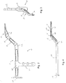
- Fig. 1 is a perspective view of a device according to an embodiment of the present invention
- Fig. 2 is a top elevation view of a device according to an embodiment of the present invention.
- Fig. 3 is a front view of a device according to an embodiment of the present invention.
- Fig. 4 is a side elevation view of a device according to an embodiment of the present invention.
- Fig. 5 is a perspective view of an example of an attachment mechanism adapted for use in connection with a device according to an embodiment of the present invention
- Fig. 6 is a cross-section view of an example of an attachment mechanism adapted for use in connection with a device according to an embodiment of the present invention
- Fig. 7 is a perspective view of an attachment mechanism according to an embodiment of the present invention.
- Fig. 8 is a cross-section view of an attachment mechanism adapted for use with a device according to an embodiment of the present invention.
- Fig. 9 is a cross-section view of an example of an attachment mechanism adapted for use in connection with a device according to an embodiment of the present invention.
- Fig. 10 is an example of a control mechanism adapted for use with a device according to an embodiment of the present invention.
- Fig. 11 is a cross-section view of a control mechanism adapted for use in connection with a device according to an embodiment of the present invention
- Fig. 12 is a perspective view of a control mechanism adapted for use in connection with a device according to an embodiment of the present invention
- Fig. 13 is a connection mechanism adapted for use with a device according to an embodiment of the present invention.
- Fig. 14 is a cross-section view of a connection mechanism adapted for use with a device according to an embodiment of the present invention.
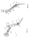
- Fig. 15 is a perspective view of a device according to an embodiment of the present invention.
- Fig. 16 is a cross-section view of an attachment mechanism adapted for use in connection with a device according to an embodiment of the present invention
- Fig. 17 is an exploded view of an alternative attachment mechanism adapted for use in connection with a device according to an embodiment of the present invention.
- Fig. 18 is a cross section view of the attachment mechanism shown in Fig. 17 in an open position
- Fig. 19 is an elevation view of the attachment mechanism of Fig. 17 in an open position
- Fig. 20 is a cross section view of the attachment mechanism of Fig. 17 in a closed position.
- Fig. 21 is an elevation view of the attachment mechanism of Fig. 17 in a closed position.
- a surgical device designated generally by reference numeral 10.
- reference numeral 10 in accordance with one embodiment of the present invention, a surgical device designated generally by reference numeral 10.
- this nomenclature is used only for convenience and that it is not intended to be limiting with respect to the scope or structure of the invention.
- the device is understood to be described only with respect to its orientation and position during an exemplary application to the human body.
- device 10 includes handle 12 and shaping instrument 14.
- Shaping instrument 14 is of the type typically used in shaping the proximal portion of a femur during hip replacement surgery. Shaping instrument 14 varies in size in accordance with the amount of material to be removed from the femoral canal in order to insert the desired replacement implant. Often, a series of shaping instruments will be used, each successive shaping instrument increasing in size in order to achieve the appropriate shape for the proximal femur.
- shaping instrument 14 has a shape that matches that of the femoral implant that is to be inserted into the femoral medullary canal.
- shaping instrument 14 has a width such that it defines a medial-lateral plane through the center thereof.
- Shaping instrument 14 has two outside surfaces 15 that are substantially parallel to and spaced apart from the medial-lateral plane through the center of shaping instrument 14. These surfaces 15 are formed with a plurality of cutting teeth (not shown) that allow the shaping instrument to remove material from the medullary canal of the proximal femur.
- Shaping instrument 14 can be in the form of either a femoral rasp or a femoral broach. The design of these devices is generally known in the art.
- Handle 12 is divided into a distal section 16, a transition section 18, and a proximal section 20.
- Handle 12 is made of a material that is sufficiently rigid so as to withstand the force needed to properly align and impact shaping instrument 14 into the femoral medullary canal through use in multiple surgical procedures. Suitable materials for handle 12 are stainless steal, titanium or other similar materials.
- proximal section 20 may further include a grip 22 or impaction surface 24. Grip 22 allows the user of device 10 to easily hold onto handle 12 during use thereof for purposes of alignment or introduction and removal of shaping instrument 12 with respect to the femoral medullary canal.
- Impaction surface 24 provides an area on the proximal end 20 of device 10 upon which the handle can be struck with a hammer, mallet or other such device in order to force shaping instrument 14 into the femoral medullary canal.
- handle 12 can be adapted to be used with an automatic impaction device, as it is known in the art.
- Handle portion 12 is connected to shaping instrument 14 at distal section 16.
- Transition section 18 extends from distal section 16 and links distal section 16 to proximal section 20 such that an appropriate compound offset between proximal section 20 and shaping instrument 14 is achieved.
- transition section 16 extends from distal section 18 to proximal section 20 so that proximal section 20 is substantially parallel to shaping instrument 14, being offset therefrom in both the anterior and medial directions.
- Shaping instrument 14 has a longitudinal axis oriented generally in the proximal-distal direction.
- proximal section 20 has a longitudinal axis oriented in the proximal-distal direction, and defines a medial-lateral plane. The distance of the offset in each direction should be such that shaping instrument 14, can be inserted into the femoral medullary canal using a generally anterior approach, while allowing proximal section 20 of handle 12 to be positioned outside of the wound and while minimizing interference with the soft tissue that surrounds the hip joint of the patient.
- proximal section 20 is offset from shaping instrument 14 in the anterior direction by at least 1 inch, but by no more than 3 inches. Similarly, it is preferred that proximal section is offset from the shaping instrument in the medial direction by at least 2 inches, but by no more than 6 inches. Most preferably proximal section is offset from shaping instrument by about 2 inches in the anterior direction and by about 4 inches in the medial direction.
- Transition section 18 has a longitudinal axis that is angled relative to the longitudinal axis of shaping instrument 14 in both the medial direction and the anterior direction. Similarly, the longitudinal axis of transition portion 18 is angled relative to the longitudinal axis of proximal section 20 in a posterior direction and a lateral direction. This necessitates the incorporation of a series of bends into device 10. As shown in Fig. 1, medial bend 26 is incorporated into shaping instrument 14. It is also possible to incorporate medial bend 26 in distal section 16 of handle 12. Medial bend 26 is preferably between 30 and 60 degrees, but is most preferably about 45 degrees. Further locations of medial bend 26 would be apparent to those having reasonable skill in the art having read this disclosure.
- anterior bend 28 is incorporated into handle 12 at the point where distal section 16 meets transition section 18.
- Anterior bend 28 is preferably between 15 and 45 degrees, but is most preferably about 30 degrees.
- Posterior bend 30 and lateral bend 32 are generally positioned at or near the point where transition section 18 meets proximal section 20. Further, posterior bend 30 and lateral bend 32 can be located at approximately the same point in handle 12 forming a compound angle.
- posterior bend 30 is of an angle approximately equal to that of anterior bend 28, and lateral bend 32 is about equal to the angle of medial bend 26, such that the longitudinal axes of proximal section 20 and shaping instrument 14 are approximately parallel.
- shaping instrument 14 and handle 12 can be integrally formed together, it is preferred that shaping instrument 14 is removably attached to handle 12.
- This arrangement allows different forms of shaping instrument 14, including those of different sizes, to be used with a single handle 12.
- One form of an attachment mechanism 34 is shown in Fig. 4, wherein bore 36 is formed in the attachment surface 37 of distal end 16.
- Trunion 46 attached to proximal end 44 of shaping instrument 14, fits within hole 36 and has notch 48 formed therein.
- Threaded hole 35 is formed in distal section 16 such that it can engage set screw 41 and such that it forms an intersection 39.
- Set screw is sized and positioned such that it can be turned within threaded hole 35, advancing the end of set screw through intersection 39 and into engagement with notch 48.
- trunion 46 is secured within bore 36, thereby affixing shaping instrument 14 to handle 12.
- FIG. 5 An alternative form of attachment mechanism 34 used for fastening shaping instrument 14 to handle 12 is shown in Figs. 5 and 6.
- This type of mechanism 34 is included in distal section 16 of handle 12, and includes first bore 36 in distal section 16 of handle 12 extending from attachment surface 37 of handle 12 in a direction orthogonal thereto.
- Distal section 16 further includes a second bore 38 running from the posterior surface of distal section 16 to the anterior surface thereof in a direction orthogonal thereto.
- Second bore 38 is positioned within distal section 16 to form an intersection 39 with first bore 36.
- Cam 40 is inserted into second bore 38 and has an undercut 42 formed therein.
- the proximal end of rasp 44 includes a trunion 46 having a notch 48 formed therein.
- Cam 40 is rotatable within second hole 38 such that it is positionable either in an open position or a closed position.
- the open position is such that undercut 42 of cam 40 is positioned such that cam 40 does not extend through intersection 39 into first bore 46.
- the closed position is such that undercut 42 is turned away from intersection 39, such that cam 40 extends through the intersection 39 and into first hole 36.
- trunion 46 When cam 40 is in the open position, trunion 46 may freely pass into and out of first bore 36.
- handle 12 and shaping instrument 14 are assembled together, trunion 46 is inserted into first bore 36 and cam 40 is rotated into the closed position. In the closed position, a portion of cam 40 extends into first bore 36 and engages notch 48 of trunion 46, such that trunion 46 is secured within second bore 36. This results in shaping instrument 14 being secured to handle 12.
- attachment surface 37 of handle 12 can include a projection 44 that mates with an opening in the proximal end of the shaping instrument 14. This arrangement prevents rotational movement of shaping instrument 14 with respect to handle 12.
- Attachment mechanism 134 includes slot 136 formed in distal section 16 of handle 12 that mates with trunion 46 formed on the proximal portion 44 of shaping instrument 14.
- Distal portion 16 of handle 12 further includes a first bore 138 formed between and orthogonal to the anterior and posterior surfaces of distal section 16.
- First bore 138 is positioned such that it forms intersection 139 with the medial side of slot 136.
- Cam 140 having undercut 142, is positioned in second bore 138 such that it is rotatable between an open position and a closed position. In the open position, undercut 142 of cam 140 is oriented such that cam 140 does not extend through intersection 139 or into slot 136.
- Second bore 150 is formed parallel to first bore 138 such that it forms an intersection with the lateral end of slot 136. Second bore 150 has a fixed post 152 secured therein that extends into a portion of slot 136.
- trunion 146 allows cam 140 to freely pass in and out of slot 136.
- slot 136 should have a length sufficient to allow trunion to clear post 152.
- cam 140 When cam 140 is rotated into the closed position, cam 140 pushes trunion 146 toward the medial end of slot 136 such that notch 148 formed in trunion 146 mates with post 152, thereby securing trunion 146 within slot 136, and thus, securing shaping instrument 14 to distal section 16.
- Handle 12 has a generally hollow structure defining cavity 153 therein. Within cavity 153 there is included slide member 155 that is slideable in the proximal-distal direction. Plate 154 is affixed to the outside surface of the handle 12 on the lateral section thereof in order to secure slide member within cavity 153.
- the proximal end of spring 156 is attached to the proximal end of handle 12, and the distal end of spring 156 is attached to slide member 155 such that it urges slide member 155 toward the proximal end of the handle 12.
- Distal end of slide member 155 includes a fork 158, which is attached using pin 160 to slot 162 formed in lever 164 that is attached to cam 140 extending from bore 38 to the outside of distal section 16. In this mechanism, when slide 155 is in its natural position, toward the proximal end of handle 12, cam 140 is forced into the closed position.
- pin 157 secured within fork 158 pushes forward on lever 64 causing cam 40 to rotate into its open position.
- connection mechanism Due to positioning of the elements of connection mechanism within distal section 16 of handle 12, it may be necessary to provide a slide member 155 that urges cam 140 into the open position by sliding in the proximal direction. If this is necessary, spring 156 will be such that it urges slide member 155 in the distal direction.
- FIG. 12 An alternative control mechanism is shown in Fig. 12, in which cam 40 is affixed to an elongated lever 66 that extends along transition portion 18 of handle 12 generally in the proximal direction. To selectively control the rotation of cam as between the open and closed positions the user rotates lever 68 in the appropriate direction.
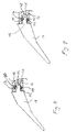
- FIGs. 13 and 14 there is shown an alternative attachment mechanism 234 for removably affixing shaping instrument 14 to handle 12.
- This attachment mechanism 234 includes a slot 236 formed in distal section 16 of handle 12 that is oriented orthogonally with respect to the attachment surface 37 of handle 12. Slot 236 is adapted to engage trunion 246 which is affixed to proximal section 44 of rasp 14.
- Distal section 16 of handle 12 includes bore 150 that has a fixed post 252 secured therein that is adapted to engage notch 248 formed in trunion 246.
- Cavity 270 is formed in transition section 18 and distal section 16 of handle 12 and two corresponding sets of slots 274 are formed through the outside wall of transition section 18 to provide access to cavity 270.
- Slots 274 are preferably generally oriented at approximately a forty-five degree angle with respect to the longitudinal axis of transition portion 18. This results in slots 274 being oriented approximately in the anterior-posterior direction. Slots 274 and are adapted to engage pins 276, which are affixed to arm 272 disposed in cavity 270, such that pins 276 lie on a anterior-posterior plane. Pins 276 are affixed to and provide support for arm 272 which has hook section 280 formed thereon. Hook section 280 is slideably engaged with wedge 278 which is slideably mounted in cavity 270 such that it can be slid into and out from intersection 239 between cavity 270 and the proximal end of slot 236.
- trunion 246 is inserted into slot 236 at the end nearest wedge 278 such that proximal end 44 of rasp 14 contacts attachment surface 37 of handle 12. Pins are then slid in the posterior direction, forcing arm 272 to move within cavity in the same direction such that it exerts a force on wedge 278.
- the slideable engagement between wedge and downwardly-extending portion of arm allows wedge to move within slots toward distal end of handle, thereby pushing trunion 246 toward and into engagement with post 252 such that trunion 246 is secured within slot 236.
- Attachment mechanism 234 is secured in the closed position by the friction generated between all of the moving parts of this arrangement, in particular between pins 276 and slots 274 and between hook section 280 and wedge 278.
- attachment mechanism 434 includes actuator 436, which is rotatably affixed within a cavity 450 formed within transition portion 18 of handle 12.
- the rotatable fixation of actuator 436 to handle 12 is preferably achieved using pin 438, which passes through properly aligned holes 440, 442 formed respectively in actuator 436 and handle 12.
- Actuator is affixed to arm 444, which is preferably in the form of a leaf spring, preferably using pin 446.
- Arm 444 extends through cavity 450 and into distal portion 16 of handle 12.
- cavity 450 also partially extends into distal portion 16.
- Wedge 448 is slideably affixed in the portion of cavity 450 that extends into distal portion 16 such that the distal end 460 of arm 444 contacts the proximal surface of wedge 448.
- Actuator 436 and arm 444 are structured such that the rotation of actuator 436 causes arm 444 to slide within cavity in a direction substantially parallel to the longitudinal axis of transition portion 18. The sliding of arm 444 causes arm 444 to push wedge 448.
- distal end 460 of arm 444 is designed to slide along the proximal surface of wedge 448 during the sliding motion of the parts to accommodate the difference in direction of the movement. Further, distal end 460 is preferably shaped such that it will not interfere with the inside of cavity 450 as arm is slid partially into distal portion 16.
- the distal surface of wedge is arranged to contact pin 462, which in slideably engaged within hole 464 formed in distal portion 16 so as to open to cavity 450.
- Pin 462 includes an angled surface that serves to transfer the motion of wedge 448, which is in a direction perpendicular to the longitudinal axis of hole 464, into motion of pin 462 in a direction parallel to the longitudinal axis of hole 464.
- arm 444 is preferably in the form of a leaf spring and is shaped so as to have a curved section 466 at the proximal end thereof.
- This arrangement allows for compression of arm 444 when the mechanism is in the "closed" position, i.e. when the actuator is turned such that arm 444 exerts a force on wedge, which in turn exerts a force onto pin that holds pin 462 in a position such that pin 462 engages notch 48 formed in post 46 of cutting instrument 14.
- the compression of arm 444 in when mechanism 434 is in the closed position can compensate for any wear that may occur with respect to the parts included in mechanism 434 due to repeated use because the compression can be made such that it is greater than any wear that is likely to occur.
- the compression of arm 444 can provide a constant force between pin 462 and notch 48, resulting in a more secure attachment of cutting instrument 14 to handle 12.
- the compression of leaf spring occurs primarily in curved portion 466 such that curved portion 466 is curved to a greater extent by the compression of arm 444.
- the arrangement of actuator 436 with respect to arm 444 is such that the maximum amount of compression for arm 444 occurs before actuator is rotated fully into the closed position. This arrangement serves to provide a force to actuator 436 that urges actuator 436 to remain in the closed position once placed as such.
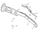
- a portion of actuator 436 extends along a portion of proximal section 20 of handle 12. As shown in Fig. 17, this requires a series of bends to be incorporated into actuator 436 that substantially match posterior 30 and lateral 32 bends that are formed in handle 12. Further, a portion of cavity 450 may be formed to extend into proximal section 20 in which actuator 436 may extend when actuator 436 is in the closed position. Further still, actuator 436 may include a flange 437 to aid a user in the manipulation thereof.
- FIG. 15-16 an alternative embodiment of device 310 is shown in which device 310 is adapted to attach to joint implant 314.
- joint implant 314 is shown as a femoral hip stem implant, it is not limited as such.
- Device 10 of the present invention could be used in connection with similar procedures conducted on any joint of the body that can be replaced, including the shoulder, knee or wrist.
- Implant 314 shown is of the type generally used in hip replacement surgery and includes a stem section 315 and a post section 317 that is adapted to engage a ball portion (not shown) of the artificial joint typical of such an arrangement.
- Implant 314 has a threaded hole 380 formed therein that is adapted to mate with a rotating threaded post 382 that is affixed to distal section 316 of handle 312.
- Distal section 316 has further affixed thereon a support 384 that is adapted to engage post 317 affixed to the proximal end of implant 314.
- threaded hole 380 is aligned with post 382 and then post 382 is turned to engage the threads between hole 380 and post 382 which draws implant 314 into contact with distal portion 316 of handle 312.
- Support 384 is used to restrict the rotational movement of implant 314 with respect to the handle 312 and to help maintain an appropriate position for implant 314 with respect to handle 312.
- the rotational movement of post 382 is controlled by knob 386 which extends from transition section 318 of handle 312. Knob 386 is attached to rod 388 which extends through transition section 318 toward distal section 320. Rod 388 is attached to post 382 using universal joint 390. Universal joint 390 transfers rotational motion about a longitudinal axis of rod 388 into rotational motion about a longitudinal axis of post 382 where the longitudinal axes of the respective elements are oblique relative to each other. The use of such a universal joint 390 is known in the art.
- a device is used by selecting an appropriate femoral implant 314 and attaching that femoral implant 314 to handle 310. Then handle 312 is used to insert femoral implant 314 through an incision created during surgery and into the proximal end of the femur having been appropriately prepared to receive implant 314. Implant 314 is then aligned using handle 312 which can be aided by including a radio frequency identification (RFID) device (not shown) either in distal section 316 the handle or in implant 314.
- RFID radio frequency identification
- knob 386 is rotated so as to detach implant 314 from handle 312. Implant 314 is then checked for proper reduction. If necessary, handle 312 is reattached to implant 314 which can be repositioned using handle 312. Once proper reduction is achieved, handle 312 is removed from the incision and the surgery is completed.
Landscapes
- Health & Medical Sciences (AREA)
- Life Sciences & Earth Sciences (AREA)
- Surgery (AREA)
- Orthopedic Medicine & Surgery (AREA)
- Veterinary Medicine (AREA)
- General Health & Medical Sciences (AREA)
- Oral & Maxillofacial Surgery (AREA)
- Engineering & Computer Science (AREA)
- Biomedical Technology (AREA)
- Heart & Thoracic Surgery (AREA)
- Public Health (AREA)
- Animal Behavior & Ethology (AREA)
- Molecular Biology (AREA)
- Nuclear Medicine, Radiotherapy & Molecular Imaging (AREA)
- Medical Informatics (AREA)
- Dentistry (AREA)
- Transplantation (AREA)
- Physical Education & Sports Medicine (AREA)
- Cardiology (AREA)
- Vascular Medicine (AREA)
- Prostheses (AREA)
- Surgical Instruments (AREA)
Priority Applications (1)
| Application Number | Priority Date | Filing Date | Title |
|---|---|---|---|
| EP10163915.1A EP2236107B1 (fr) | 2006-03-06 | 2007-03-06 | Poignée déportée pour composants |
Applications Claiming Priority (1)
| Application Number | Priority Date | Filing Date | Title |
|---|---|---|---|
| US11/368,761 US7935125B2 (en) | 2006-03-06 | 2006-03-06 | Compound offset handle |
Related Child Applications (2)
| Application Number | Title | Priority Date | Filing Date |
|---|---|---|---|
| EP10163915.1A Division EP2236107B1 (fr) | 2006-03-06 | 2007-03-06 | Poignée déportée pour composants |
| EP10163915.1 Division-Into | 2010-05-26 |
Publications (3)
| Publication Number | Publication Date |
|---|---|
| EP1832248A2 true EP1832248A2 (fr) | 2007-09-12 |
| EP1832248A3 EP1832248A3 (fr) | 2007-11-07 |
| EP1832248B1 EP1832248B1 (fr) | 2012-11-28 |
Family
ID=38124054
Family Applications (2)
| Application Number | Title | Priority Date | Filing Date |
|---|---|---|---|
| EP10163915.1A Active EP2236107B1 (fr) | 2006-03-06 | 2007-03-06 | Poignée déportée pour composants |
| EP07103548A Active EP1832248B1 (fr) | 2006-03-06 | 2007-03-06 | Poignée déportée pour composants |
Family Applications Before (1)
| Application Number | Title | Priority Date | Filing Date |
|---|---|---|---|
| EP10163915.1A Active EP2236107B1 (fr) | 2006-03-06 | 2007-03-06 | Poignée déportée pour composants |
Country Status (4)
| Country | Link |
|---|---|
| US (4) | US7935125B2 (fr) |
| EP (2) | EP2236107B1 (fr) |
| AU (1) | AU2007200979B2 (fr) |
| CA (1) | CA2581517C (fr) |
Cited By (5)
| Publication number | Priority date | Publication date | Assignee | Title |
|---|---|---|---|---|
| FR2926208A1 (fr) * | 2008-01-08 | 2009-07-17 | X Nov | Ancillaire, notamment pour la pose d'une prothese de hanche. |
| US8425526B2 (en) | 2006-10-17 | 2013-04-23 | Smith & Nephew, Inc. | Adjustable impactor |
| WO2014167258A1 (fr) * | 2013-04-11 | 2014-10-16 | Etablissement Maurice Marle | Manche amovible muni d'un dispositif d'assemblage démontable |
| US20240207067A1 (en) * | 2022-12-27 | 2024-06-27 | Depuy Ireland Unlimited Company | Orthopaedic surgical instrument, system, and method for installing a cemented femoral stem component in a direct anterior approach hip replacement surgical procedure |
| WO2024201213A1 (fr) * | 2023-03-29 | 2024-10-03 | DePuy Synthes Products, Inc. | Instrument chirurgical orthopédique pour extraire un composant de tige fémorale dans une procédure chirurgicale de remplacement de hanche et son procédé d'utilisation |
Families Citing this family (46)
| Publication number | Priority date | Publication date | Assignee | Title |
|---|---|---|---|---|
| US8657824B2 (en) * | 2003-11-18 | 2014-02-25 | Smith & Nephew, Inc. | Universal double offset surgical instrument |
| EP1696807B1 (fr) | 2003-11-18 | 2009-09-30 | Smith & Nephew, Inc. | Technique chirurgicale et instrumentation pour une chirurgie de la hanche par arthroplastie avec incision minimale |
| US7935125B2 (en) | 2006-03-06 | 2011-05-03 | Howmedica Osteonics Corp. | Compound offset handle |
| FR2924771B1 (fr) * | 2007-12-05 | 2012-12-28 | Marnaise Applic Orthopediques Smao Soc | Systeme d'encliquetage avec verrouillage entre deux elements |
| WO2009100247A1 (fr) * | 2008-02-05 | 2009-08-13 | Texas Scottish Rite Hospital For Children | Anneau de fixation externe |
| JP5507472B2 (ja) | 2008-02-08 | 2014-05-28 | テキサス スコティッシュ ライト ホスピタル フォー チルドレン | 創外固定支柱 |
| EP2249721B1 (fr) | 2008-02-12 | 2017-07-05 | Texas Scottish Rite Hospital For Children | Tige de liaison de fixation externe à ajustement rapide |
| WO2009105479A1 (fr) * | 2008-02-18 | 2009-08-27 | Texas Scottish Rite Hospital For Children | Outil et procédé d’ajustement d’entretoise de fixation externe |
| US8052755B2 (en) | 2008-05-09 | 2011-11-08 | Remi Sciences, Inc. | Ulnar head prosthesis system |
| US7875082B2 (en) | 2008-05-09 | 2011-01-25 | Remi Sciences, Inc. | Ulnar head prosthesis system |
| DE102009024654B4 (de) * | 2009-06-12 | 2021-01-28 | Peter Brehm Holding Gmbh & Co. Kg | Wechselgriff für ein Funktionsteil und chirurgische Vorrichtung |
| FR2947169B1 (fr) * | 2009-06-30 | 2012-04-27 | Xnov | Porte rape de hanche a machoire mobile |
| US8966867B2 (en) * | 2009-12-29 | 2015-03-03 | Howmedica Osteonics Corp. | Implant package |
| WO2012023876A1 (fr) | 2010-08-20 | 2012-02-23 | Amei Technologies, Inc. | Procédé et système permettant une modélisation basée sur une radiographie |
| US9119644B2 (en) * | 2010-08-21 | 2015-09-01 | New York Society For The Ruptured And Crippled Maintaining The Hospital For Special Surgery | Instruments for use in femoroacetabular impingement procedures |
| US9456810B2 (en) | 2012-01-13 | 2016-10-04 | Smith & Nephew, Inc. | Surgical instrument handle assembly |
| US20130261626A1 (en) * | 2012-03-29 | 2013-10-03 | Jason M. Chavarria | Orthopaedic surgical instrument for removing an implanted humeral stem component and method of using the same |
| US9610084B2 (en) | 2012-09-12 | 2017-04-04 | Peter Michael Sutherland Walker | Method and apparatus for hip replacements |
| US9084685B2 (en) * | 2012-09-28 | 2015-07-21 | DePuy Synthes Products, Inc. | Femoral prosthesis with insertion/extraction feature |
| US10667798B2 (en) | 2012-10-29 | 2020-06-02 | Zimmer, Inc. | Surgical tool handle assemblies and related methods |
| US8574232B1 (en) | 2012-11-13 | 2013-11-05 | Texas Scottish Hospital for Children | External fixation connection rod for rapid and gradual adjustment |
| US9554810B2 (en) | 2013-03-15 | 2017-01-31 | Depuy Ireland Unlimited Company | Femoral system handle surgical instrument and method of assembling same |
| US10064629B2 (en) * | 2014-07-30 | 2018-09-04 | Zimmer, Inc. | Bone perforator |
| US9987043B2 (en) | 2014-10-24 | 2018-06-05 | Stryker European Holdings I, Llc | Methods and systems for adjusting an external fixation frame |
| JP2018501905A (ja) * | 2015-01-15 | 2018-01-25 | デピュイ・シンセス・プロダクツ・インコーポレイテッド | 組立工具 |
| USD806493S1 (en) | 2015-07-22 | 2018-01-02 | Tti (Macao Commercial Offshore) Limited | Tool adapter |
| USD780548S1 (en) | 2015-07-22 | 2017-03-07 | Ac (Macao Commercial Offshore) Limited | Power tool |
| US10368913B2 (en) | 2015-08-10 | 2019-08-06 | Stryker European Holdings I, Llc | Adjustment instrument with tactile feedback |
| US11246624B2 (en) * | 2015-11-06 | 2022-02-15 | Joint Development, Llc | Broach holder tool with reduced rasp moment |
| US11116509B2 (en) | 2017-11-10 | 2021-09-14 | Avantec Vascular Corporation | System and method for delivering an embolic device |
| CN112789010B (zh) | 2018-10-04 | 2025-01-28 | 德普伊爱尔兰无限公司 | 假体提取系统 |
| US11660201B2 (en) * | 2018-10-25 | 2023-05-30 | Wright Medical Technology, Inc. | Systems, apparatuses, and methods for correcting a bone defect |
| USD929589S1 (en) * | 2019-01-18 | 2021-08-31 | Shukla Medical | Surgical striking apparatus |
| GB201901590D0 (en) * | 2019-02-05 | 2019-03-27 | Smith & Nephew Orthopaedics Ag | Robust impactor |
| WO2020229143A2 (fr) * | 2019-05-14 | 2020-11-19 | Loci Orthopaedics Limited | Ensemble d'outils pour installer un implant |
| US11622869B2 (en) * | 2019-07-29 | 2023-04-11 | Tri-Sphere Holdings | Femoral component extractor |
| US12370051B2 (en) * | 2019-10-01 | 2025-07-29 | Howmedica Osteonics Corp. | Shoulder prosthesis components and assemblies |
| US11382634B2 (en) | 2019-12-18 | 2022-07-12 | Avantec Vascular Corporation | Embolic device suited for ease of delivery and placement |
| US11602359B2 (en) | 2020-01-24 | 2023-03-14 | Zimmer, Inc. | Rasp handle adapter |
| US11617660B2 (en) * | 2020-06-12 | 2023-04-04 | Tri-Sphere Holdings, LLC | Femoral component extractor |
| JP7465982B2 (ja) * | 2020-08-25 | 2024-04-11 | 京セラ株式会社 | ネックトライアル、手術器具システムおよびネックトライアルの製造方法 |
| CN112773579B (zh) * | 2021-01-29 | 2023-07-25 | 北京市春立正达医疗器械股份有限公司 | 一种试垫取出器 |
| CN113974922B (zh) * | 2021-10-29 | 2025-04-18 | 天衍医疗器材有限公司 | 可持多种股骨柄弯型击入调整器 |
| CN113974761B (zh) * | 2021-11-30 | 2023-06-20 | 优适医疗科技(苏州)有限公司 | 髋关节股骨侧髓腔锉辅助装置 |
| DE102021134527A1 (de) | 2021-12-23 | 2023-06-29 | Aesculap Ag | Implantationssystem |
| US20240293238A1 (en) * | 2023-03-03 | 2024-09-05 | Depuy Ireland Unlimited Company | Orthopaedic surgical instrument, system, and method for installing a cementless femoral stem component in a direct anterior approach hip replacement surgical procedure |
Family Cites Families (32)
| Publication number | Priority date | Publication date | Assignee | Title |
|---|---|---|---|---|
| US3955568A (en) | 1975-04-17 | 1976-05-11 | Neufeld Alonzo J | Tool and method for use in total hip implant |
| US4583270A (en) * | 1983-04-15 | 1986-04-22 | Pfizer Hospital Products Group, Inc. | Rasp handle |
| US4587964A (en) | 1985-02-05 | 1986-05-13 | Zimmer, Inc. | Rasp tool |
| US4921493A (en) | 1986-08-11 | 1990-05-01 | Zimmer, Inc. | Rasp tool |
| US4765328A (en) | 1987-08-10 | 1988-08-23 | Osteonics Corp. | Surgical instrument handle coupling |
| US4990149A (en) * | 1989-01-24 | 1991-02-05 | Richards Medical Company | Releasable orthopedic broach handle apparatus |
| US5089003A (en) | 1989-12-22 | 1992-02-18 | Zimmer, Inc. | Rasp tool including detachable handle member |
| US5190550A (en) * | 1990-08-02 | 1993-03-02 | Exactech, Inc. | Locking surgical tool handle system |
| US5190549A (en) | 1990-08-02 | 1993-03-02 | Exactech, Inc. | Locking surgical tool handle system |
| US5352230A (en) * | 1992-02-19 | 1994-10-04 | Biomet, Inc. | Pneumatic impulse tool |
| US5324293A (en) * | 1992-11-13 | 1994-06-28 | U.S. Medical Products, Inc. | Surgical broach and broach holder |
| US5443471A (en) * | 1993-02-16 | 1995-08-22 | Howmedica, Inc. | Quick release handle assembly |
| EP0619097B1 (fr) | 1993-04-07 | 1999-06-23 | Sulzer Orthopädie AG | Râpe et manche accouplable pour la préparation du canal médullaire d'un os destiné à recevoir une prothèse |
| DE4332872C1 (de) | 1993-09-27 | 1995-04-06 | Zsolt Szabo | Ausschlagwerkzeug für Gelenkprothesen |
| US5581892A (en) * | 1995-05-30 | 1996-12-10 | Dean; James A. | Filleting and skinning knife |
| FR2742334B1 (fr) | 1995-12-18 | 1998-05-15 | Maurice Lanzoni | Dispositif developpeur d'effort d'un prehenseur universel de tige femorale |
| US5993455A (en) | 1996-11-13 | 1999-11-30 | Noble; Philip C. | Surgical broach and methods for preparing the medullary cavity of a femur in hip arthroplasty |
| US5810830A (en) | 1996-11-13 | 1998-09-22 | Howmedica Inc. | Machining assembly and methods for preparing the medullary cavity of a femur in hip arthroplasty |
| US5919195A (en) | 1998-01-20 | 1999-07-06 | Johnson & Johnson Professional, Inc. | Oblong acetabular component instrumentation |
| DE29807671U1 (de) | 1998-04-28 | 1999-09-02 | Link Waldemar Gmbh Co | Chirurgisches Instrument |
| US6197062B1 (en) * | 1999-01-11 | 2001-03-06 | Howmedica Osteonics, Corp. | Modular shoulder prosthesis system |
| EP1158939A1 (fr) | 1999-03-03 | 2001-12-05 | Smith & Nephew, Inc. | Procedes, systemes et instruments d'introduction d'implants prothetiques |
| US6991656B2 (en) | 2000-04-26 | 2006-01-31 | Dana Mears | Method and apparatus for performing a minimally invasive total hip arthroplasty |
| JP4649745B2 (ja) | 2001-02-01 | 2011-03-16 | ソニー株式会社 | 発光素子の転写方法 |
| AU2003219465A1 (en) * | 2002-04-30 | 2003-11-17 | Precimed S.A. | Reamer spindle for minimally invasive joint surgery |
| US20040010261A1 (en) | 2002-07-12 | 2004-01-15 | Hoag Stephen H. | Tool for releasably gripping an orthopedic implant |
| FR2850010B1 (fr) | 2003-01-17 | 2005-12-02 | Tornier Sa | Ancillaire de pose d'un cotyle prothetique pour une prothese de hanche |
| EP1696807B1 (fr) | 2003-11-18 | 2009-09-30 | Smith & Nephew, Inc. | Technique chirurgicale et instrumentation pour une chirurgie de la hanche par arthroplastie avec incision minimale |
| US8657824B2 (en) | 2003-11-18 | 2014-02-25 | Smith & Nephew, Inc. | Universal double offset surgical instrument |
| US20070093897A1 (en) | 2005-10-21 | 2007-04-26 | Stryker Spine (In France) | System and method for fusion cage implantation |
| US7935125B2 (en) | 2006-03-06 | 2011-05-03 | Howmedica Osteonics Corp. | Compound offset handle |
| US20080255565A1 (en) | 2006-11-20 | 2008-10-16 | Fletcher Henry H | Broach handle for minimally invasive hip replacement surgery |
-
2006
- 2006-03-06 US US11/368,761 patent/US7935125B2/en active Active
-
2007
- 2007-03-06 AU AU2007200979A patent/AU2007200979B2/en active Active
- 2007-03-06 EP EP10163915.1A patent/EP2236107B1/fr active Active
- 2007-03-06 CA CA2581517A patent/CA2581517C/fr active Active
- 2007-03-06 EP EP07103548A patent/EP1832248B1/fr active Active
-
2011
- 2011-03-07 US US13/041,789 patent/US8337502B2/en active Active
-
2012
- 2012-11-30 US US13/691,128 patent/US8512345B2/en not_active Expired - Lifetime
-
2013
- 2013-06-26 US US13/927,512 patent/US8690880B2/en not_active Expired - Lifetime
Cited By (9)
| Publication number | Priority date | Publication date | Assignee | Title |
|---|---|---|---|---|
| US8425526B2 (en) | 2006-10-17 | 2013-04-23 | Smith & Nephew, Inc. | Adjustable impactor |
| FR2926208A1 (fr) * | 2008-01-08 | 2009-07-17 | X Nov | Ancillaire, notamment pour la pose d'une prothese de hanche. |
| WO2014167258A1 (fr) * | 2013-04-11 | 2014-10-16 | Etablissement Maurice Marle | Manche amovible muni d'un dispositif d'assemblage démontable |
| FR3004331A1 (fr) * | 2013-04-11 | 2014-10-17 | Maurice Marle Ets | Manche amovible muni d'un dispositif d'assemblage demontable |
| CN105120805A (zh) * | 2013-04-11 | 2015-12-02 | 莫里斯马尔勒公司 | 设置有用于可拆卸组装的装置的可移除手柄 |
| CN105120805B (zh) * | 2013-04-11 | 2017-04-26 | 莫里斯马尔勒公司 | 设置有用于可拆卸组装的装置的可移除手柄 |
| US9796074B2 (en) | 2013-04-11 | 2017-10-24 | Etablissements Maurice Marle | Removable handle provided with a device for detachable assembly |
| US20240207067A1 (en) * | 2022-12-27 | 2024-06-27 | Depuy Ireland Unlimited Company | Orthopaedic surgical instrument, system, and method for installing a cemented femoral stem component in a direct anterior approach hip replacement surgical procedure |
| WO2024201213A1 (fr) * | 2023-03-29 | 2024-10-03 | DePuy Synthes Products, Inc. | Instrument chirurgical orthopédique pour extraire un composant de tige fémorale dans une procédure chirurgicale de remplacement de hanche et son procédé d'utilisation |
Also Published As
| Publication number | Publication date |
|---|---|
| EP1832248B1 (fr) | 2012-11-28 |
| US8690880B2 (en) | 2014-04-08 |
| AU2007200979A1 (en) | 2007-09-20 |
| US20130090657A1 (en) | 2013-04-11 |
| US8337502B2 (en) | 2012-12-25 |
| US8512345B2 (en) | 2013-08-20 |
| US20130289566A1 (en) | 2013-10-31 |
| CA2581517A1 (fr) | 2007-09-06 |
| US20110160734A1 (en) | 2011-06-30 |
| EP1832248A3 (fr) | 2007-11-07 |
| AU2007200979B2 (en) | 2012-07-26 |
| EP2236107B1 (fr) | 2014-04-16 |
| US20070233134A1 (en) | 2007-10-04 |
| CA2581517C (fr) | 2011-06-07 |
| US7935125B2 (en) | 2011-05-03 |
| EP2236107A1 (fr) | 2010-10-06 |
Similar Documents
| Publication | Publication Date | Title |
|---|---|---|
| EP2236107B1 (fr) | Poignée déportée pour composants | |
| US20080033444A1 (en) | Compound offset handle | |
| US12109127B2 (en) | Implant inserter having a laterally-extending dovetail engagement feature | |
| JP6433665B2 (ja) | オフセットを設定するための脛骨の整形外科用手術器具 | |
| JP6591142B2 (ja) | オフセット設定のための脛骨トライアル器具 | |
| CN103445828B (zh) | 胫骨整形外科器械及其使用方法 | |
| US9039710B2 (en) | Prosthetic inserter | |
| US9216089B2 (en) | Method of surgically preparing a patient's tibia | |
| EP2567676A1 (fr) | Support d'épaule réversible et extensible | |
| US20120101504A1 (en) | Flexible attachment for an extramedullary surgical instrument | |
| EP1444957A1 (fr) | Appareil pour aligner un instrument lors d'une intervention chirurgicale | |
| JP7608462B2 (ja) | インプラント挿入ツールのための取り外し可能な傾斜ガイドおよび関連する外科的方法 | |
| WO2010065233A1 (fr) | Dispositif d'exposition d'articulation | |
| AU2011239283B2 (en) | Compound offset handle | |
| US20230016885A1 (en) | Broach Handle | |
| US20250025317A1 (en) | Implant Inserter Having a Laterally-Extending Dovetail Engagement Feature | |
| JP2026501996A (ja) | 直接前方アプローチ股関節置換外科処置においてセメント接合された大腿骨ステムコンポーネントを設置するための整形外科用器具、システム、及び方法 |
Legal Events
| Date | Code | Title | Description |
|---|---|---|---|
| PUAI | Public reference made under article 153(3) epc to a published international application that has entered the european phase |
Free format text: ORIGINAL CODE: 0009012 |
|
| 17P | Request for examination filed |
Effective date: 20070306 |
|
| AK | Designated contracting states |
Kind code of ref document: A2 Designated state(s): AT BE BG CH CY CZ DE DK EE ES FI FR GB GR HU IE IS IT LI LT LU LV MC MT NL PL PT RO SE SI SK TR |
|
| AX | Request for extension of the european patent |
Extension state: AL BA HR MK YU |
|
| PUAL | Search report despatched |
Free format text: ORIGINAL CODE: 0009013 |
|
| AK | Designated contracting states |
Kind code of ref document: A3 Designated state(s): AT BE BG CH CY CZ DE DK EE ES FI FR GB GR HU IE IS IT LI LT LU LV MC MT NL PL PT RO SE SI SK TR |
|
| AX | Request for extension of the european patent |
Extension state: AL BA HR MK YU |
|
| 17Q | First examination report despatched |
Effective date: 20080326 |
|
| AKX | Designation fees paid |
Designated state(s): AT BE BG CH CY CZ DE DK EE ES FI FR GB GR HU IE IS IT LI LT LU LV MC MT NL PL PT RO SE SI SK TR |
|
| GRAC | Information related to communication of intention to grant a patent modified |
Free format text: ORIGINAL CODE: EPIDOSCIGR1 |
|
| GRAP | Despatch of communication of intention to grant a patent |
Free format text: ORIGINAL CODE: EPIDOSNIGR1 |
|
| GRAS | Grant fee paid |
Free format text: ORIGINAL CODE: EPIDOSNIGR3 |
|
| GRAA | (expected) grant |
Free format text: ORIGINAL CODE: 0009210 |
|
| AK | Designated contracting states |
Kind code of ref document: B1 Designated state(s): AT BE BG CH CY CZ DE DK EE ES FI FR GB GR HU IE IS IT LI LT LU LV MC MT NL PL PT RO SE SI SK TR |
|
| REG | Reference to a national code |
Ref country code: GB Ref legal event code: FG4D |
|
| REG | Reference to a national code |
Ref country code: CH Ref legal event code: EP |
|
| REG | Reference to a national code |
Ref country code: AT Ref legal event code: REF Ref document number: 585747 Country of ref document: AT Kind code of ref document: T Effective date: 20121215 |
|
| REG | Reference to a national code |
Ref country code: IE Ref legal event code: FG4D |
|
| REG | Reference to a national code |
Ref country code: DE Ref legal event code: R096 Ref document number: 602007026943 Country of ref document: DE Effective date: 20130124 |
|
| REG | Reference to a national code |
Ref country code: AT Ref legal event code: MK05 Ref document number: 585747 Country of ref document: AT Kind code of ref document: T Effective date: 20121128 |
|
| REG | Reference to a national code |
Ref country code: NL Ref legal event code: VDEP Effective date: 20121128 |
|
| REG | Reference to a national code |
Ref country code: LT Ref legal event code: MG4D |
|
| PG25 | Lapsed in a contracting state [announced via postgrant information from national office to epo] |
Ref country code: ES Free format text: LAPSE BECAUSE OF FAILURE TO SUBMIT A TRANSLATION OF THE DESCRIPTION OR TO PAY THE FEE WITHIN THE PRESCRIBED TIME-LIMIT Effective date: 20130311 Ref country code: LT Free format text: LAPSE BECAUSE OF FAILURE TO SUBMIT A TRANSLATION OF THE DESCRIPTION OR TO PAY THE FEE WITHIN THE PRESCRIBED TIME-LIMIT Effective date: 20121128 Ref country code: SE Free format text: LAPSE BECAUSE OF FAILURE TO SUBMIT A TRANSLATION OF THE DESCRIPTION OR TO PAY THE FEE WITHIN THE PRESCRIBED TIME-LIMIT Effective date: 20121128 Ref country code: FI Free format text: LAPSE BECAUSE OF FAILURE TO SUBMIT A TRANSLATION OF THE DESCRIPTION OR TO PAY THE FEE WITHIN THE PRESCRIBED TIME-LIMIT Effective date: 20121128 |
|
| PG25 | Lapsed in a contracting state [announced via postgrant information from national office to epo] |
Ref country code: PT Free format text: LAPSE BECAUSE OF FAILURE TO SUBMIT A TRANSLATION OF THE DESCRIPTION OR TO PAY THE FEE WITHIN THE PRESCRIBED TIME-LIMIT Effective date: 20130328 Ref country code: CY Free format text: LAPSE BECAUSE OF FAILURE TO SUBMIT A TRANSLATION OF THE DESCRIPTION OR TO PAY THE FEE WITHIN THE PRESCRIBED TIME-LIMIT Effective date: 20121128 Ref country code: GR Free format text: LAPSE BECAUSE OF FAILURE TO SUBMIT A TRANSLATION OF THE DESCRIPTION OR TO PAY THE FEE WITHIN THE PRESCRIBED TIME-LIMIT Effective date: 20130301 Ref country code: LV Free format text: LAPSE BECAUSE OF FAILURE TO SUBMIT A TRANSLATION OF THE DESCRIPTION OR TO PAY THE FEE WITHIN THE PRESCRIBED TIME-LIMIT Effective date: 20121128 Ref country code: PL Free format text: LAPSE BECAUSE OF FAILURE TO SUBMIT A TRANSLATION OF THE DESCRIPTION OR TO PAY THE FEE WITHIN THE PRESCRIBED TIME-LIMIT Effective date: 20121128 Ref country code: BE Free format text: LAPSE BECAUSE OF FAILURE TO SUBMIT A TRANSLATION OF THE DESCRIPTION OR TO PAY THE FEE WITHIN THE PRESCRIBED TIME-LIMIT Effective date: 20121128 Ref country code: SI Free format text: LAPSE BECAUSE OF FAILURE TO SUBMIT A TRANSLATION OF THE DESCRIPTION OR TO PAY THE FEE WITHIN THE PRESCRIBED TIME-LIMIT Effective date: 20121128 |
|
| PG25 | Lapsed in a contracting state [announced via postgrant information from national office to epo] |
Ref country code: AT Free format text: LAPSE BECAUSE OF FAILURE TO SUBMIT A TRANSLATION OF THE DESCRIPTION OR TO PAY THE FEE WITHIN THE PRESCRIBED TIME-LIMIT Effective date: 20121128 |
|
| PG25 | Lapsed in a contracting state [announced via postgrant information from national office to epo] |
Ref country code: EE Free format text: LAPSE BECAUSE OF FAILURE TO SUBMIT A TRANSLATION OF THE DESCRIPTION OR TO PAY THE FEE WITHIN THE PRESCRIBED TIME-LIMIT Effective date: 20121128 Ref country code: CZ Free format text: LAPSE BECAUSE OF FAILURE TO SUBMIT A TRANSLATION OF THE DESCRIPTION OR TO PAY THE FEE WITHIN THE PRESCRIBED TIME-LIMIT Effective date: 20121128 Ref country code: BG Free format text: LAPSE BECAUSE OF FAILURE TO SUBMIT A TRANSLATION OF THE DESCRIPTION OR TO PAY THE FEE WITHIN THE PRESCRIBED TIME-LIMIT Effective date: 20130228 Ref country code: SK Free format text: LAPSE BECAUSE OF FAILURE TO SUBMIT A TRANSLATION OF THE DESCRIPTION OR TO PAY THE FEE WITHIN THE PRESCRIBED TIME-LIMIT Effective date: 20121128 Ref country code: DK Free format text: LAPSE BECAUSE OF FAILURE TO SUBMIT A TRANSLATION OF THE DESCRIPTION OR TO PAY THE FEE WITHIN THE PRESCRIBED TIME-LIMIT Effective date: 20121128 |
|
| PG25 | Lapsed in a contracting state [announced via postgrant information from national office to epo] |
Ref country code: RO Free format text: LAPSE BECAUSE OF FAILURE TO SUBMIT A TRANSLATION OF THE DESCRIPTION OR TO PAY THE FEE WITHIN THE PRESCRIBED TIME-LIMIT Effective date: 20121128 Ref country code: IT Free format text: LAPSE BECAUSE OF FAILURE TO SUBMIT A TRANSLATION OF THE DESCRIPTION OR TO PAY THE FEE WITHIN THE PRESCRIBED TIME-LIMIT Effective date: 20121128 Ref country code: NL Free format text: LAPSE BECAUSE OF FAILURE TO SUBMIT A TRANSLATION OF THE DESCRIPTION OR TO PAY THE FEE WITHIN THE PRESCRIBED TIME-LIMIT Effective date: 20121128 |
|
| PLBE | No opposition filed within time limit |
Free format text: ORIGINAL CODE: 0009261 |
|
| STAA | Information on the status of an ep patent application or granted ep patent |
Free format text: STATUS: NO OPPOSITION FILED WITHIN TIME LIMIT |
|
| PG25 | Lapsed in a contracting state [announced via postgrant information from national office to epo] |
Ref country code: MC Free format text: LAPSE BECAUSE OF NON-PAYMENT OF DUE FEES Effective date: 20130331 |
|
| REG | Reference to a national code |
Ref country code: CH Ref legal event code: PL |
|
| 26N | No opposition filed |
Effective date: 20130829 |
|
| REG | Reference to a national code |
Ref country code: DE Ref legal event code: R097 Ref document number: 602007026943 Country of ref document: DE Effective date: 20130829 |
|
| PG25 | Lapsed in a contracting state [announced via postgrant information from national office to epo] |
Ref country code: LI Free format text: LAPSE BECAUSE OF NON-PAYMENT OF DUE FEES Effective date: 20130331 Ref country code: CH Free format text: LAPSE BECAUSE OF NON-PAYMENT OF DUE FEES Effective date: 20130331 |
|
| PG25 | Lapsed in a contracting state [announced via postgrant information from national office to epo] |
Ref country code: MT Free format text: LAPSE BECAUSE OF FAILURE TO SUBMIT A TRANSLATION OF THE DESCRIPTION OR TO PAY THE FEE WITHIN THE PRESCRIBED TIME-LIMIT Effective date: 20121128 |
|
| PG25 | Lapsed in a contracting state [announced via postgrant information from national office to epo] |
Ref country code: TR Free format text: LAPSE BECAUSE OF FAILURE TO SUBMIT A TRANSLATION OF THE DESCRIPTION OR TO PAY THE FEE WITHIN THE PRESCRIBED TIME-LIMIT Effective date: 20121128 |
|
| PG25 | Lapsed in a contracting state [announced via postgrant information from national office to epo] |
Ref country code: HU Free format text: LAPSE BECAUSE OF FAILURE TO SUBMIT A TRANSLATION OF THE DESCRIPTION OR TO PAY THE FEE WITHIN THE PRESCRIBED TIME-LIMIT; INVALID AB INITIO Effective date: 20070306 Ref country code: LU Free format text: LAPSE BECAUSE OF NON-PAYMENT OF DUE FEES Effective date: 20130306 |
|
| REG | Reference to a national code |
Ref country code: FR Ref legal event code: PLFP Year of fee payment: 10 |
|
| PG25 | Lapsed in a contracting state [announced via postgrant information from national office to epo] |
Ref country code: IS Free format text: LAPSE BECAUSE OF FAILURE TO SUBMIT A TRANSLATION OF THE DESCRIPTION OR TO PAY THE FEE WITHIN THE PRESCRIBED TIME-LIMIT Effective date: 20121128 |
|
| REG | Reference to a national code |
Ref country code: FR Ref legal event code: PLFP Year of fee payment: 11 |
|
| REG | Reference to a national code |
Ref country code: FR Ref legal event code: PLFP Year of fee payment: 12 |
|
| P01 | Opt-out of the competence of the unified patent court (upc) registered |
Effective date: 20230522 |
|
| PGFP | Annual fee paid to national office [announced via postgrant information from national office to epo] |
Ref country code: FR Payment date: 20251231 Year of fee payment: 20 |
|
| PGFP | Annual fee paid to national office [announced via postgrant information from national office to epo] |
Ref country code: GB Payment date: 20260106 Year of fee payment: 20 |
|
| PGFP | Annual fee paid to national office [announced via postgrant information from national office to epo] |
Ref country code: IE Payment date: 20260102 Year of fee payment: 20 Ref country code: DE Payment date: 20260102 Year of fee payment: 20 |