EP1832361B1 - Stranggiesskokille - Google Patents
Stranggiesskokille Download PDFInfo
- Publication number
- EP1832361B1 EP1832361B1 EP07004791A EP07004791A EP1832361B1 EP 1832361 B1 EP1832361 B1 EP 1832361B1 EP 07004791 A EP07004791 A EP 07004791A EP 07004791 A EP07004791 A EP 07004791A EP 1832361 B1 EP1832361 B1 EP 1832361B1
- Authority
- EP
- European Patent Office
- Prior art keywords
- mould
- guide
- casting
- tube
- continuous casting
- Prior art date
- Legal status (The legal status is an assumption and is not a legal conclusion. Google has not performed a legal analysis and makes no representation as to the accuracy of the status listed.)
- Not-in-force
Links
- 238000009749 continuous casting Methods 0.000 title claims description 32
- 238000005266 casting Methods 0.000 claims abstract description 48
- 238000001816 cooling Methods 0.000 claims description 12
- 230000033001 locomotion Effects 0.000 claims description 11
- 239000007921 spray Substances 0.000 description 6
- 230000015572 biosynthetic process Effects 0.000 description 4
- 239000000498 cooling water Substances 0.000 description 3
- 230000000295 complement effect Effects 0.000 description 2
- 230000005484 gravity Effects 0.000 description 2
- 230000005540 biological transmission Effects 0.000 description 1
- 230000003247 decreasing effect Effects 0.000 description 1
- 238000011161 development Methods 0.000 description 1
- 230000018109 developmental process Effects 0.000 description 1
- 230000000694 effects Effects 0.000 description 1
- 239000004744 fabric Substances 0.000 description 1
- 239000003779 heat-resistant material Substances 0.000 description 1
- 229910001338 liquidmetal Inorganic materials 0.000 description 1
- 239000000463 material Substances 0.000 description 1
- 229920001225 polyester resin Polymers 0.000 description 1
- 239000004645 polyester resin Substances 0.000 description 1
- 239000012858 resilient material Substances 0.000 description 1
- 239000000725 suspension Substances 0.000 description 1
- 239000012209 synthetic fiber Substances 0.000 description 1
- 229920002994 synthetic fiber Polymers 0.000 description 1
- XLYOFNOQVPJJNP-UHFFFAOYSA-N water Substances O XLYOFNOQVPJJNP-UHFFFAOYSA-N 0.000 description 1
Images




Classifications
-
- B—PERFORMING OPERATIONS; TRANSPORTING
- B22—CASTING; POWDER METALLURGY
- B22D—CASTING OF METALS; CASTING OF OTHER SUBSTANCES BY THE SAME PROCESSES OR DEVICES
- B22D11/00—Continuous casting of metals, i.e. casting in indefinite lengths
- B22D11/04—Continuous casting of metals, i.e. casting in indefinite lengths into open-ended moulds
- B22D11/043—Curved moulds
-
- B—PERFORMING OPERATIONS; TRANSPORTING
- B22—CASTING; POWDER METALLURGY
- B22D—CASTING OF METALS; CASTING OF OTHER SUBSTANCES BY THE SAME PROCESSES OR DEVICES
- B22D11/00—Continuous casting of metals, i.e. casting in indefinite lengths
- B22D11/04—Continuous casting of metals, i.e. casting in indefinite lengths into open-ended moulds
- B22D11/051—Continuous casting of metals, i.e. casting in indefinite lengths into open-ended moulds into moulds having oscillating walls
Definitions
- the present invention relates to a continuous casting mold according to the preamble of claim 1.
- the EP 0 984 836 B1 describes a continuous casting mold with integrated Schwingvorrichung, in which the mold tube has a curved casting axis and the Kokillenrohr is excited substantially in the casting direction to an oscillating motion.
- the mold tube is cooled by cooling water flowing around the mold tube, so that a mold housing which tightly surrounds the mold tube must be present.
- the unit of Kokillengeophuse and Kokillenrohr with the cooling water is excited to vibrate, and thereby guided in the horizontal direction, ie substantially perpendicular to the casting direction by means of a guide ring.
- the doctrine of EP 0 984 836 B1 is, among other things, to let oscillate only the absolutely necessary part of the continuous casting, so that the mass to be excited vibration is minimized.
- the DE 195 37 745 A1 discloses a continuous casting mold for casting a strand having a continuous mold cavity enclosing side walls.
- the continuous casting mold has at least two mutually opposite side walls, which are rigidly fixed relative to each other about a Eing manabexcellent the Kokillenhohlraum and have a decreasing in the direction of passage of the strand taper.
- the side walls have in a direction of passage of the strand downstream of the Eing manab mustard outlet portion of the Kokillenhohlraums sidewall sections, which are movable against the strand and can be pressed by means of Anpress drivingen to the strand.
- the side wall portions are arranged with a smaller conicity than the smallest conicity of the side walls of the Eing manabexcellents the Kokillenhohlraums.
- the lower end of the mold tube In the continuous casting mold, the lower end of the mold tube, viewed in the casting direction, is guided parallel to a tangent to the casting axis in this lower region of the mold tube.
- the continuous casting mold according to a first embodiment of the invention has a curved casting axis.
- the casting axis is assumed to be the outer radius of the mold tube having the radius of curvature R.
- the curved casting axis it is also possible to assume the curved casting axis as the center line of the mold tube, as indicated by the reference numeral 11 in FIG Fig. 1 that mentioned in the introduction EP 1 337 361 B1 is shown.
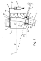
- the continuous casting mold has a mold housing 1, a curved mold tube 2 with a radius of curvature R (as defined above), one in the detail views of FIG Fig. 2 to 6 shown cooling device 3, an actuator 4 for exciting the Kokillenrohrs 2 to an oscillating movement substantially along the casting axis, and a guide 5 on.
- the mold tube 2 is arranged inside the mold tube housing 1.
- cooling device 3 is designed as a spray cooling device with spray nozzles 31 which cools the mold tube 2 during the casting process within the mold housing by spray cooling.
- a flange 23, or attached thereto Seen in the casting direction upper end 22 of the mold tube is provided with a flange 23, or attached thereto.
- the flange 23 is pivotally mounted on a lever arm 43 of the actuator 4 via a pivot bearing about an axis of rotation A.
- the lever arm 43 is for Pivoting about a pivot point D formed.
- the lever arm 43 is deflected by an actuator 41 of the actuator 4 such as a pneumatic or hydraulic cylinder or the like to an oscillating movement. This can, for example, as in Fig. 1 shown, done via the piston rod 42 of a reciprocating piston.
- the configuration of the actuator 4 with respect to both the operating member 41 and the transmission arrangement by means of levers or the like is not limited to the embodiment shown in the figures.
- the flange 23 is deflected at a frequency in the range of 1 to 10 Hz, preferably 2 to 5 Hz with a stroke in the range of 4 to 20 mm, preferably 6 to 12 mm.
- the length of the mold tube is usually in the range of 300 to 1200 mm, preferably in the range of 600 to 1000 mm.
- the guide 5 is formed by an outer part 52 which is fixed to the mold housing 1, and an inner part 51 which is fixed to the mold tube 2.
- the outer part 52 has a Groove into which an annular guide member 53 is inserted.
- groove and guide part 53 may also be provided on the inner part 51.
- the guide member 53 is, according to a preferred embodiment, a guide ring formed of a heat-resistant and resilient material, such as e.g. a guide ring made of FHO the company Seal Concept GmbH, 86399 Bobingen, DE.
- the material FHO is a combination of a synthetic fiber fabric and a polyester resin.
- the guide ring is annular, wherein the circular plane forms a guide plane which is perpendicular to the tangent T1 and contains the intersection S1.
- the circular plane of the guide ring is inclined at an angle ⁇ relative to a horizontal plane perpendicular to gravity.
- the guide member 53 is fixed in a groove on the inside of the outer part 52. Since the guide member 53 is annular, the surface cooperating with this guide member, in this case the opposite outer surface of the inner member 51, has a corresponding circular cylindrical shape at least in the region where the outer surface comes into contact with the guide member 53 , Analogously, the outer part 52 on its inner side to a circular cylindrical shape of the inner part 51 complementary circular cylindrical shape, so that the parts are movable relative to each other. Of course, the circular cylindrical shapes also have the angle ⁇ relative to the horizontal plane.
- the guide points 5fi, 5fa on guide surfaces 511, 531 are the guide points 5fi, 5fa on guide surfaces 511, 531, of which the guide surface 511 is located on the outside of the inner part 51 and the guide surface 531 lies on the inside of the guide member 53, and which enclose the mold tube 2.
- the guide surfaces 511, 531 are annular, or circular cylindrical in this embodiment.
- a convex or toroidal shape for the corresponding surface of the guide member 53 and / or the outer surface of the inner member 51 and the inner surface of the outer member 52 would also be possible, so that the corresponding guide surface then a circular line, that is circular.
- the guide plane F is at the intersection S of the casting axis G and the connecting line V perpendicular to the casting axis G.
- the mold tube is guided parallel to the tangent T1 during the oscillating movement.
- the mold tube Due to the annular formation of the guide element 53 (and the complementary annular formation of the opposite surface of the inner part 51), the mold tube is also free to rotate about the casting axis.
- the guide member 53 may be a square ring. Then, the inner part 51 and the outer part 52 have on their inside or outside corresponding square cylindrical shapes. In the case of an angular formation of the guide part, however, the degree of freedom about the casting axis is no longer given.
- the actuator 4 at the in Fig. 1 shown schematic representation of the actuator 4, and in particular its actuating element 41, arranged on the outside of the origin U of the mold housing 1.
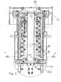
- the actuator 4, and in particular its actuating element 41 but arranged on the origin U facing the inside of the mold housing 1, as shown in Fig. 2 you can see.
- the pivot point D is shown, and the lever 43 is on the in Fig. 2 right side to see.
- the actuator 41, the in Fig. 2 is not shown, attacks at the point K and deflects this oscillating, as indicated by the arrow KB.
- the arrangement of the actuator 4 on the side facing the origin U of the mold housing this is better protected against splashing liquid metal.
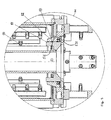
- Fig. 3 is the storage of the flange 23 so that it is rotatable about the axis A, to recognize well.
- Fig. 7 shows a second embodiment of the invention.
- Fig. 7 not only the lower region 21 of the mold tube 2 seen in the casting direction but also the upper region 22 of the mold tube 2 seen in the casting direction is guided by a correspondingly formed guide 5.
- the upper region via which the oscillating movement is introduced into the mold tube, is guided along the tangent T2 to the curvature of the mold tube in this upper region 22.
- the upper region 22 seen in the casting direction is fastened to a flange 26 which at the same time serves as the inner part 51 of the guide 5.
- This flange 26 (51) is excited by means of a lever arrangement 42, 43 of the actuator 4 and the actuating element 41 for oscillating movement.
- the connecting line from the origin U of the radius of curvature R through the upper region 22 of the mold tube 2 seen in the casting direction is denoted by V2.
- the corresponding point of intersection of the connecting line V2 with the curvature is denoted by S2 and the tangent to the curvature in point S2 of intersection with T2.
- the second embodiment corresponds to the first embodiment
- the embodiments of the guide 5 of the first embodiment apply analogously to the two guides 5 of the second embodiment.
- a spray cooling is shown.
- the mold housing is preferably sealed on its underside so that no water can escape.
- the cooling could also be carried out as a flow cooling with cooling water. Then, in the illustrated embodiments, the seal is to be adapted for flow cooling.
- the effect of the described invention is significant in terms of increasing the life of the guides.
- angles ⁇ result (see Fig. 1 ), depending on the position of the parallel to the tangent tangent to the radius of curvature, from 2 to 5 degrees.
- the angle ⁇ can be well over 5 degrees. Therefore, the reduction of bearing forces achieved by the invention is significant.
Landscapes
- Engineering & Computer Science (AREA)
- Mechanical Engineering (AREA)
- Continuous Casting (AREA)
- Detail Structures Of Washing Machines And Dryers (AREA)
- Led Devices (AREA)
- Supercharger (AREA)
- Exhaust Silencers (AREA)
Description
- Die vorliegende Erfindung betrifft eine Stranggießkokille nach dem Oberbegriff des Anspruchs 1.
- Stranggießvorrichtungen in Form von Stranggießkokillen sind im Stand der Technik seit langem bekannt. Die
EP 0 984 836 B1 beschreibt eine Stranggießkokille mit integrierter Schwingvorrichung, bei der das Kokillenrohr eine gekrümmte Gießachse aufweist und das Kokillenrohr im Wesentlichen in Gießrichtung zu einer oszillierenden Bewegung angeregt wird. Das Kokillenrohr wird durch das Kokillenrohr umströmendes Kühlwasser gekühlt, so dass ein das Kokillenrohr dicht umgebendes Kokillengehäuse vorhanden sein muss. Die Einheit aus Kokillengehäuse und Kokillenrohr mit dem Kühlwasser wird zur Schwingung angeregt, und dabei in horizontaler Richtung, also im Wesentlichen senkrecht zur Gießrichtung, mittels eines Führungsrings geführt. Die Lehre derEP 0 984 836 B1 ist unter anderem, nur noch den unbedingt notwendigen Teil der Stranggießvorrichtung oszillieren zu lassen, damit die zur Schwingung anzuregende Masse möglichst gering gehalten wird. - Dieses Anliegen liegt unter anderem auch der aus der
US 4,483,385 bekannten Stranggießvorrichtung zugrunde, die ebenfalls ein Kokillenrohr mit gekrümmter Gießachse aufweist, bei der eine Sprühkühlung vorhanden ist, die es ermöglicht, nur das Kokillenrohr und seine Aufhängung schwingen zu lassen. Bei dieser Anordnung ist das in Gießrichtung gesehen obere Ende des Kokillenrohrs mit einem Stellglied zur Anregung der Schwingung verbunden, während das in Gießrichtung gesehene untere Ende des Kokillenrohres frei beweglich ist. - Die
DE 195 37 745 A1 offenbart eine Stranggießkokille zum Gießen eines Strangs, die einen Durchlaufkokillenhohlraum umschließende Seitenwände aufweist. Die Stranggießkokille weist mindestens zwei einander gegenüberliegende Seitenwände auf, die um einen Eingießabschnitt des Kokillenhohlraums starr gegeneinander fixiert sind und eine in Durchlaufrichtung des Strangs abnehmende Konizität aufweisen. Die Seitenwände weisen in einem in Durchlaufrichtung des Strangs dem Eingießabschnitt nachgeordneten Auslaufabschnitt des Kokillenhohlraums Seitenwandabschnitte auf, die gegen den Strang beweglich und mittels Anpresseinrichtungen an den Strang anpressbar sind. Die Seitenwandabschnitte sind mit einer geringeren Konizität angeordnet als die geringste Konizität der Seitenwände des Eingießabschnitts des Kokillenhohlraums. - Aus der
EP 1 337 361 B1 und aus derDE-AS-1 508 808 ist jeweils eine Stranggießkokille nach dem Oberbegriff des Anspruchs 1 bekannt, bei der ein Kokillenrohr mit gekrümmter Gießachse und eine Sprühkühlung vorgesehen sind. Im Vergleich zu der aus derUS 4,483,385 bekannten Anordnung wird das in Gießrichtung gesehen untere Ende des Kokillenrohres durch eine Führungsvorrichtung in vertikaler Richtung bewegbar und in horizontaler Richtung gegen ein Verdrehen um die Gießachse gesichert führt. - Es ist eine Aufgabe der vorliegenden Erfindung, eine Stranggießkokille mit einem Kokillenrohr mit gekrümmter Gießachse anzugeben, die ein verbessertes Schwingverhalten und eine verbesserte Langlebigkeit aufweist.
- Diese Aufgabe wird gelöst durch eine Stranggießkokille nach Anspruch 1.
- Weiterbildungen der Erfindung sind in den Unteransprüchen angegeben.
- Bei der Stranggießkokille wird das in Gießrichtung gesehen untere Ende des Kokillenrohrs parallel zu einer Tangente an die Gießachse in diesem unteren Bereich des Kokillenrohrs geführt.
- Dadurch werden die Kräfte, die in die Führung während der oszillierenden Bewegung des Kokillenrohres eingeleitet werden, minimiert, was einerseits den Verschleiß der Führung minimiert und andererseits das Schwingungsverhalten des Kokillenrohres im Hinblick auf den Strangguss verbessert.
- Nach einer weiter verbesserten Ausführungsform wird nicht nur das in Gießrichtung gesehen untere Ende sondern auch das in Gießrichtung gesehen obere Ende des Kokillenrohres derartig geführt, d.h. parallel zu einer Tangente an die Gießachse in den jeweiligen geführten Bereich.
- Weitere Merkmale und Zweckmäßigkeiten ergeben sich aus der Beschreibung von Ausführungsbeispielen anhand der Figuren. Von den Figuren zeigen:
- Fig. 1
- eine Prinzipdarstellung einer Stranggießkokille nach einer ersten Ausführungsform der Erfindung in einer Schnittansicht mit einer Schnittebene, die von der Gießrichtung und dem Krümmungsradius der Stranggießkokille aufgespannt wird;
- Fig. 2
- eine detaillierte Schnittansicht der ersten Ausführungsform in einer Blickrichtung, die der Blickrichtung aus
Fig. 1 entgegengesetzt ist; - Fig. 3
- eine Schnittansicht der Stranggießvorrichtung der ersten Ausführungsform, wobei die Schnittebene senkrecht zu der Schnittebene der
Fig. 1 und2 ist; - Fig. 4
- eine Detailansicht des in
Fig. 2 vom Kreis DA 1 umgebenen Bereichs, - Fig. 5
- eine Detailansicht des in
Fig. 3 vom Kreis DA2 umgebenen Bereichs, - Fig. 6
- eine Schnittansicht entlang der Linie P-P aus
Fig. 2 ; und - Fig. 7
- eine Ansicht einer zweiten Ausführungsform der Erfindung, die der Ansicht aus
Fig. 1 entspricht. - Zuerst wird eine erste Ausführungsform der Erfindung im Detail geschrieben. Wie in
Fig. 1 gezeigt ist, weist die Stranggießkokille nach einer ersten Ausführungsform der Erfindung eine gekrümmte Gießachse auf. In der vorliegenden Anmeldung wird die Gießachse als der Außenradius des Kokillenrohres mit dem Krümmungsradius R angenommen. Alternativ ist es auch möglich die gekrümmte Gießachse als Mittelinie des Kokillenrohrs anzunehmen, wie dies durch das Bezugszeichen 11 inFig. 1 der in der Beschreibungseinleitung genanntenEP 1 337 361 B1 gezeigt ist. Da übliche Krümmungsradien von gekrümmten Stranggießkokillenrohren im Bereich von 4000 bis 12000 mm liegen, während der Durchmesser des Kokillenrohres im Bereich von wenigen 100 mm liegt, spielt dieser Unterschied keine wesentliche Rolle und alle möglichen Krümmungsradien in dem Bereich von dem Ursprung U des Krümmungsradius bis zur dem Ursprung U zugewandten Innenseite 24 als Untergrenze bis zu der dem Ursprung U abgewandten Außenseite 25 des Kokillenrohres 2 als Obergrenze sollen in der nachfolgenden Anmeldung als Krümmungsradien R des Kokillenrohres 2 bzw. der Gießachse angesehen werden. - Die Stranggießkokille weist ein Kokillengehäuse 1, ein gekrümmtes Kokillenrohr 2 mit einem Krümmungsradius R (gemäß der obigen Definition), eine in den Detailansichten der
Fig. 2 bis 6 gezeigte Kühlvorrichtung 3, ein Stellglied 4 zum Anregen des Kokillenrohrs 2 zu einer oszillierenden Bewegung im Wesentlichen entlang der Gießachse, und eine Führung 5 auf. - Das Kokillenrohr 2 ist innerhalb des Kokillenrohrgehäuses 1 angeordnet. Die in
Fig. 1 nicht gezeigte aber in denFig. 2 bis 6 gezeigte Kühlvorrichtung 3 ist als eine Sprühkühlvorrichtung mit Sprühdüsen 31 ausgebildet, die das Kokillenrohr 2 während des Gießvorgangs innerhalb des Kokillengehäuses durch Sprühkühlung kühlt. - Das in Gießrichtung gesehen obere Ende 22 des Kokillenrohres ist mit einem Flansch 23 versehen, bzw. an diesem befestigt. Der Flansch 23 ist über ein Drehlager um eine Drehachse A schwenkbar an einem Hebelarm 43 des Stellgliedes 4 gelagert. Der Hebelarm 43 ist zum Schwenken um einen Drehpunkt D ausgebildet. Der Hebelarm 43 wird von einem Betätigungselement 41 des Stellgliedes 4 wie einem Pneumatik- oder Hydraulikzylinder oder ähnlichem zu einer oszillierenden Bewegung ausgelenkt. Dieses kann z.B., wie in
Fig. 1 gezeigt, über die Kolbenstange 42 eines Hubkolbens erfolgen. Die Ausbildung des Stellgliedes 4 sowohl hinsichtlich des Betätigungselements 41 als auch hinsichtlich der Übertragungsanordnung mittels Hebeln oder Ähnlichem ist nicht auf die in den Figuren gezeigte Ausführungsform begrenzt. - Bei einer bevorzugten Ausführungsform wird der Flansch 23 mit einer Frequenz im Bereich von 1 bis 10 Hz, bevorzugt 2 bis 5 Hz mit einem Hub im Bereich von 4 bis 20 mm, bevorzugt 6 bis 12 mm ausgelenkt.
- Die Länge des Kokillenrohres liegt üblicherweise im Bereich vom 300 bis 1200 mm, bevorzugt im Bereich von 600 bis 1000 mm.
- Bei vielen Stranggießkokillen mit gekrümmten Kokillenrohr liegt die zu der Schwerkraft parallele Tangente an die Krümmung des Kokillenrohres nicht genau am oberen Ende des Kokillenrohres, sondern oberhalb der Mitte aber deutlich unterhalb des oberen Endes des Kokillenrohres, wie es in
Fig. 1 oder derEP 1 337 361 B1 gezeigt ist. Alternativ kann auch bei dieser Ausführungsform diese zur Schwerkraft parallele Tangente aber auch am oberen Ende oder nahe des oberen Endes des Kokillenrohres befindlich sein (siehe z.B. dieUS 4,483,385 ). - Bei der in
Fig. 1 gezeigten ersten Ausführungsform wird der in Gießrichtung gesehene untere Bereich 21 des Kokillenrohrs 2 durch eine Führung 5 während der oszillierenden Bewegung des Kokillenrohrs 2 geführt. Wie inFig. 1 gut zu erkennen ist, schneidet eine gedachte gerade Verbindungslinie V1, die durch den Ursprung U des Krümmungsradius R und den geführten unteren Bereich 21 geht und diese verbindet, die dem Ursprung U abgewandte Außenseite 25 des Kokillenrohres (also die Gießachse) in einem Schnittpunkt S1. Es ist dabei offensichtlich, dass die Tangente T1 an die Krümmung des Kokillenrohres im Schnittpunkt S1 genau senkrecht zu der Verbindungslinie V1 ist. Außerdem liegt die Verbindungslinie V1 in einer Ebene, die senkrecht zur Tangente T1 ist und den Schnittpunkt S1 enthält. - Die Führung 5 wird gebildet von einem Außenteil 52, das an dem Kokillengehäuse 1 befestigt ist, und einem Innenteil 51, das an dem Kokillenrohr 2 befestigt ist. Das Außenteil 52 weist eine Nut auf, in die ein kreisringförmiges Führungsteil 53 eingesetzt ist. Alternativ können Nut und Führungsteil 53 auch an dem Innenteil 51 vorgesehen sein.
- Das Führungsteil 53 ist nach einer bevorzugten Ausführungsform ein Führungsring, der aus einem hitzebeständigen und belastbaren Material ausgebildet ist, wie z.B. ein Führungsring aus FHO der Firma Seal Concept GmbH, 86399 Bobingen, DE. Das Material FHO ist eine Kombination aus einem Kunstfasergewebe und einem Polyesterharz.
- Der Führungsring ist kreisringförmig, wobei die Kreisebene eine Führungsebene bildet, die senkrecht zur Tangente T1 ist und den Schnittpunkt S1 enthält. In anderen Worten, die Kreisebene des Führungsrings ist in einem Winkel α relativ zu einer zu der Schwerkraft senkrechten horizontalen Ebene schräg gestellt.
- Aus den
Figuren 2 und3 und den Detailansichten DA1 und DA2, die in denFiguren 4 und5 gezeigt sind, lässt sich gut erkennen, dass das Führungsteil 53 in einer Nut auf der Innenseite des Außenteils 52 befestigt ist. Da das Führungsteil 53 kreisringförmig ausgebildet ist, weist die mit diesem Führungsteil zusammenwirkende Oberfläche, in diesem Fall der die gegenüberliegende äußere Oberfläche des Innenteils 51, eine entsprechende Kreiszylinderform wenigstens in dem Bereich, in dem die äußere Oberfläche mit dem Führungsteil 53 in Kontakt kommt, auf. Analog weist das Außenteil 52 an seiner Innenseite eine zu der Kreiszylinderform des Innenteils 51 komplementäre Kreiszylinderform auf, damit die Teile relativ zueinander bewegbar sind. Die Kreiszylinderformen weisen natürlich ebenfalls den Winkel α relativ zu der horizontalen Ebene auf. - Durch diese kreisringförmige Ausbildung des Führungsteil 53 und seine entsprechende Orientierung wird sichergestellt, dass wenigstens ein Führungspunkt 5fi auf der dem Ursprung U zugewandten Innenseite 24 des Kokillenrohres und wenigstens ein Führungspunkt 5fa auf der dem Ursprung U abgewandten Außenseite 25 des Kokillenrohres 2 auf der Verbindungslinie V1 vorhanden sind.
- Durch die kreiszylinderförmige Ausbildung des Führungsteils 53 liegen die Führungspunkte 5fi, 5fa auf Führungsflächen 511, 531, von denen die Führungsfläche 511 auf der Außenseite des Innenteils 51 liegt und die Führungsfläche 531 auf der Innenseite des Führungsteils 53 liegt, und die das Kokillenrohr 2 umschließen. Die Führungsflächen 511, 531 sind kreisringförmig, bzw. bei dieser Ausführungsform kreiszylinderförmig. Eine konvex gewölbte Form oder Torusform für die entsprechende Fläche des Führungsteils 53 und/oder die Außenfläche des Innenteils 51 bzw. die Innenfläche des Außenteils 52 wäre auch möglich, so dass die entsprechende Führungsfläche dann eine Kreislinie, also kreisringförmig ist. Die Führungsflächen 511, 531, oder genauer die Kreisebene in dem Kreiszylinder, in der die Verbindungslinie V liegt, spannen eine Führungsebene F auf. Die Führungsebene F ist im Schnittpunkt S der Gießachse G und der Verbindungslinie V senkrecht zu der Gießachse G.
- Dadurch wird das Kokillenrohr während der oszillierenden Bewegung parallel zur Tangente T1 geführt.
- Durch die kreisringförmige Ausbildung des Führungselementes 53 (und die komplementär kreisringförmige Ausbildung der gegenüberliegenden Fläche des Innenteils 51) ist das Kokillenrohr außerdem frei zu einer Drehung um die Gießachse.
- In einer alternativen Ausführungsform kann das Führungsteil 53 ein eckiger Ring sein. Dann müssen das Innenteil 51 und das Außenteil 52 an ihrer Innenseite bzw. Außenseite entsprechende eckige Zylinderformen aufweisen. Im Falle einer eckigen Ausbildung des Führungsteils ist der Freiheitsgrad um die Gießachse allerdings nicht mehr gegeben.
- Bei der in
Fig. 1 gezeigten Prinzipdarstellung ist das Stellglied 4, und insbesondere dessen Betätigungselement 41, auf der dem Ursprung U abgewandten Außenseite des Kokillengehäuses 1 angeordnet. Vorteilhafterweise ist bei einer bevorzugten Ausführungsform das Stellglied 4, und insbesondere dessen Betätigungselement 41, jedoch auf der dem Ursprung U zugewandten Innenseite des Kokillengehäuses 1 angeordnet, wie dies inFig. 2 zu sehen ist. Dort ist der Drehpunkt D gezeigt, und der Hebel 43 ist auf der inFig. 2 rechten Seite zu sehen. Das Betätigungselement 41, das inFig. 2 nicht dargestellt ist, greift am Punkt K an und lenkt diesen oszillierend aus, wie es durch den Pfeil KB angedeutet ist. Durch die Anordnung des Stellgliedes 4 auf der dem Ursprung U zugewandten Seite des Kokillengehäuses wird dieses besser vor spritzendem flüssigem Metall geschützt. - In
Fig. 3 ist die Lagerung des Flansches 23 derart, dass er um die Achse A drehbar ist, gut zu erkennen. -
Fig. 7 zeigt eine zweite Ausführungsform der Erfindung. - In
Fig. 7 wird nicht nur der in Gießrichtung gesehen untere Bereich 21 des Kokillenrohrs 2 sondern auch der in Gießrichtung gesehen obere Bereich 22 des Kokillenrohrs 2 durch eine entsprechend ausgebildete Führung 5 geführt. D.h., bei der zweiten Ausführungsform wird auch der obere Bereich, über den die oszillierende Bewegung in das Kokillenrohr eingeleitet wird, entlang der Tangente T2 an die Krümmung des Kokillenrohrs in diesem oberen Bereich 22 geführt. - Dadurch werden auch die geringeren Winkelfehler, die durch eine Bewegung des oberen Bereichs 22 des Kokillenrohres, die nicht entlang des Krümmungsradius erfolgt, verursacht werden, weiter minimiert.
- Bei der zweiten Ausführungsform ist der in Gießrichtung gesehen obere Bereich 22 an einem Flansch 26 befestigt, der gleichzeitig als Innenteil 51 der Führung 5 dient. Dieser Flansch 26 (51) wird mittels einer Hebelanordnung 42, 43 des Stellgliedes 4 und des Betätigungselementes 41 zur oszillierenden Bewegung angeregt.
- Die Verbindungslinie vom Ursprung U des Krümmungsradius R durch den in Gießrichtung gesehenen oberen Bereich 22 des Kokillenrohrs 2 ist mit V2 bezeichnet. Der entsprechende Schnittpunkt der Verbindungslinie V2 mit der Krümmung ist mit S2 und die Tangente an die Krümmung in Schnittpunkt S2 mit T2 bezeichnet.
- Im Übrigen entspricht die zweite Ausführungsform der ersten Ausführungsform, und die Ausführungen zur Führung 5 der ersten Ausführungsform gelten analog für die beiden Führungen 5 der zweiten Ausführungsform.
- Bei der ersten und zweiten Ausführungsform ist eine Sprühkühlung dargestellt. Das Kokillengehäuse ist dabei bevorzugt an seiner Unterseite so abgedichtet, dass kein Wasser austreten kann. Die Kühlung könnte aber auch als Strömungskühlung mit Kühlwasser ausgeführt werden. Dann ist bei den gezeigten Ausführungsformen die Abdichtung für eine Strömungskühlung anzupassen.
- Die Wirkung der beschriebenen Erfindung ist im Hinblick auf die Erhöhung der Lebensdauer der Führungen erheblich. Bei einem Krümmungsradius R von 10000 mm ergeben sich Winkel α (siehe
Fig. 1 ), je nach der Position der zur Schwerkraft parallelen Tangente an den Krümmungsradius, von 2 bis 5 Grad. Bei einem Krümmungsradius R von 5000 mm kann der Winkel α deutlich über 5 Grad betragen. Daher ist die durch die Erfindung erzielte Reduzierung der Lagerkräfe signifikant. - Die Hinzufügung eines weiteren Freiheitsgrades für die Schwingung des Kokillenrohres um die Gießachse führt zu einer weiteren signifikanten Reduzierung des Verschleißes der Lager und der Kokillenrohre.
- Es wird explizit betont, dass alle in der Beschreibung und/oder den Ansprüchen offenbarten Merkmale als getrennt und unabhängig voneinander zum Zweck der ursprünglichen Offenbarung ebenso wie zum Zweck des Einschränkens der beanspruchten Erfindung unabhängig von den Merkmalskombinationen in den Ausführungsformen und/oder den Ansprüchen angesehen werden sollen. Es wird explizit festgehalten, dass alle Bereichsangaben oder Angaben von Gruppen von Einheiten jeden möglichen Zwischenwert oder Untergruppe von Einheiten zum Zweck der ursprünglichen Offenbarung ebenso wie zum Zweck des Einschränkens der beanspruchten Erfindung offenbaren, insbesondere auch als Grenze einer Bereichsangabe.
Claims (11)
- Stranggießkokille, mit
einem Kokillenrohr (2) mit einer gekrümmten Gießachse (G) mit einem ersten Krümmungsradius (R),
einem Stellglied (4), das angepasst ist zum oszillierenden Bewegen des Kokillenrohrs (2), und
einer Führung (5), die angepasst ist zum Führen des Kokillenrohrs während der oszillierenden Bewegung in dem in Gießrichtung gesehen unteren Bereich (21) des Kokillenrohrs (2) parallel zu einer Tangente an die Gießachse,
dadurch gekennzeichnet,
dass die Führung (5) angepasst ist zum Führen des in Gießrichtung gesehen unteren Bereichs (21) des Kokillenrohrs (2) an wenigstens zwei Führungspunkten (5fi, 5fa) auf einer ersten gedachten geraden Verbindungslinie (V1), die durch den Ursprung (U) des ersten Krümmungsradius (R) und den geführten unteren Bereich (21) des Kokillenrohrs (2) geht, von welchen zwei Führungspunkten (5fi, 5fa) je einer der Führungspunkte relativ zu dem Ursprung (U) des ersten Krümmungsradius (R) auf der dem Ursprung (U) zugewandten Innenseite (24) und auf der dem Ursprung abgewandten Außenseite (25) des Kokillenrohrs (2) derart befindlich ist, dass das Kokillenrohr (2) parallel zu einer ersten Tangente (T1) an die Gießachse (G) im Schnittpunkt (S1) der Gießachse (G) und der ersten Verbindungslinie (V1) geführt wird. - Stranggießkokille nach Anspruch 1, bei der
die Führung (5) so ausgebildet ist, dass das Kokillenrohr (2) einen Freiheitsgrad für eine Drehung um die Gießachse (G) aufweist. - Stranggießkokille nach Anspruch 1 oder 2, bei der
die Führungspunkte (5fi, 5fa) der Führung (5) auf das Kokillenrohr (2) umschließenden Führungsflächen (511, 531) liegen, die kreiszylinderförmig sind. - Stranggießkokille nach einem der Ansprüche 1 bis 3, bei der
an dem in Gießrichtung gesehen oberen Bereich (22) des Kokillenrohrs (2) ein Flansch (23; 26) angeordnet ist, der mit dem Stellglied (4) verbunden ist. - Stranggießkokille nach einem der Ansprüche 1 bis 4, bei der
eine weitere Führung (5) vorgesehen ist, die angepasst ist zum Führen des in Gießrichtung gesehen oberen Bereichs (22) des Kokillenrohrs (2) an wenigstens zwei Führungspunkten (5fi, 5fa) auf einer zweiten gedachten geraden Verbindungslinie (V2), die durch den Ursprung (U) des ersten Krümmungsradius (R) und den geführten oberen Bereich (22) des Kokillenrohrs (2) geht, von welchen zwei Führungspunkten (5fi, 5fa) je einer der Führungspunkte relativ zu dem Ursprung (U) des ersten Krümmungsradius (R) auf der dem Ursprung (U) zugewandten Innenseite (24) und auf der dem Ursprung abgewandten Außenseite (25) des Kokillenrohrs (2) befindlich ist, und zum Führen des Kokillenrohrs (2) senkrecht zu der zweiten Verbindungslinie (V2) und parallel zu einer zweiten Tangente (T2) an die Gießachse (G) im Schnittpunkt (S2) der Gießachse (G) und der zweiten Verbindungslinie (V2). - Stranggießkokille nach einem der Ansprüche 1 bis 5, bei der
die Führung (5)
ein Innenteil (51), das an dem geführten Bereich (21; 22) des Kokillenrohrs (2) angebracht ist, ein Außenteil (52), das an dem Kokillengehäuse (1) angebracht ist, und
ein Führungsteil (53), das an dem Innenteil oder an dem Außenteil angeordnet ist, aufweist. - Stranggießkokille nach einem der Ansprüche 1 bis 6, bei der
die Führung (5) angepasst ist zum Führen des Kokillenrohrs während der oszillierenden Bewegung in dem geführten Bereich (21; 22) des Kokillenrohrs (2) derart, dass das Kokillenrohr (2) frei für eine Drehung um die entsprechende erste oder zweite Tangente (T) im Schnittpunkt (S1; S2) der Gießachse (G) und der entsprechenden ersten oder zweiten Verbindungslinie (V1; V2) ist. - Stranggießkokille nach Anspruch 6 oder 7, bei der
das Führungsteil (53) kreisringförmig ist. - Stranggießkokille nach einem der Ansprüche 1 bis 8, die weiter
ein Kokillengehäuse (1)
aufweist, und bei der
die Führung(en) (5) zwischen dem Kokillengehäuse (1) und dem Kokillenrohr (2) angeordnet ist/sind. - Stranggießkokille nach Anspruch 9, die weiter
eine Kühlvorrichtung (3), die in dem Kokillengehäuse (1) angeordnet ist und das Kokillenrohr (2) in dem Kokillengehäuse kühlt,
aufweist und bei der
das Kokillengehäuse (1) abgedichtet ist. - Stranggießkokille nach Anspruch 9 oder, bei der
das Stellglied (4) auf der dem Ursprung (U) des ersten Krümmungsradius (R) zugewandten Seite des Kokillengehäuse (1) angeordnet ist.
Applications Claiming Priority (1)
| Application Number | Priority Date | Filing Date | Title |
|---|---|---|---|
| DE102006010984A DE102006010984B4 (de) | 2006-03-09 | 2006-03-09 | Stranggießkokille |
Publications (2)
| Publication Number | Publication Date |
|---|---|
| EP1832361A1 EP1832361A1 (de) | 2007-09-12 |
| EP1832361B1 true EP1832361B1 (de) | 2009-10-07 |
Family
ID=38198405
Family Applications (1)
| Application Number | Title | Priority Date | Filing Date |
|---|---|---|---|
| EP07004791A Not-in-force EP1832361B1 (de) | 2006-03-09 | 2007-03-08 | Stranggiesskokille |
Country Status (4)
| Country | Link |
|---|---|
| EP (1) | EP1832361B1 (de) |
| AT (1) | ATE444821T1 (de) |
| DE (2) | DE102006010984B4 (de) |
| ES (1) | ES2331206T3 (de) |
Families Citing this family (1)
| Publication number | Priority date | Publication date | Assignee | Title |
|---|---|---|---|---|
| CN115507180A (zh) * | 2022-10-12 | 2022-12-23 | 甘肃酒钢集团宏兴钢铁股份有限公司 | 一种结晶器铜管密封装置及其使用方法 |
Family Cites Families (5)
| Publication number | Priority date | Publication date | Assignee | Title |
|---|---|---|---|---|
| US3343592A (en) * | 1965-09-22 | 1967-09-26 | Concast Inc | Reciprocating continuous casting curved mold mounting system |
| US4483385A (en) * | 1981-11-05 | 1984-11-20 | Amb Technology, Inc. | System for oscillating mold tube in continuous steel casting machine |
| AT405253B (de) | 1994-10-11 | 1999-06-25 | Voest Alpine Ind Anlagen | Stranggiesskokille |
| LU90071B1 (de) * | 1997-05-30 | 1998-12-01 | Wurth Paul Sa | Stranggiessvorrichtung |
| LU90666B1 (en) * | 2000-10-31 | 2002-05-02 | Wurth Paul Sa | Continous casting mould with oscillation device |
-
2006
- 2006-03-09 DE DE102006010984A patent/DE102006010984B4/de not_active Expired - Fee Related
-
2007
- 2007-03-08 DE DE502007001654T patent/DE502007001654D1/de active Active
- 2007-03-08 ES ES07004791T patent/ES2331206T3/es active Active
- 2007-03-08 AT AT07004791T patent/ATE444821T1/de active
- 2007-03-08 EP EP07004791A patent/EP1832361B1/de not_active Not-in-force
Also Published As
| Publication number | Publication date |
|---|---|
| EP1832361A1 (de) | 2007-09-12 |
| DE102006010984B4 (de) | 2009-08-20 |
| ATE444821T1 (de) | 2009-10-15 |
| DE102006010984A1 (de) | 2007-09-13 |
| DE502007001654D1 (de) | 2009-11-19 |
| ES2331206T3 (es) | 2009-12-23 |
Similar Documents
| Publication | Publication Date | Title |
|---|---|---|
| EP1292768B1 (de) | Axialkolbenmaschine | |
| EP3212351B1 (de) | Strangführungsrolleneinheit für eine stranggiessmaschine | |
| DE102004028100B4 (de) | Extrusionsblaskopf | |
| DE202008014089U1 (de) | Transportvorrichtung für einen Gegenstand | |
| DE3216377A1 (de) | Vorrichtung zur herstellung von rohren aus plastischen massen | |
| EP3003679A1 (de) | Spritzgiessvorrichtung | |
| WO1998053935A1 (de) | Stranggiessvorrichtung | |
| DE2333488A1 (de) | Einstueckiger schlauch und einrichtung und verfahren zu seiner herstellung | |
| EP1832361A1 (de) | Stranggiesskokille | |
| DE102015100807B4 (de) | Schleudergusskokillenvorrichtung zur Herstellung von Bremsscheiben und deren Verwendung | |
| DE102009020409A1 (de) | Rotordüse | |
| DE102008039211A1 (de) | Rohrtarget mit Endblock zur Kühlmittelversorgung | |
| DE102004057974B4 (de) | Extrusionskopf mit Düsenspalteinstellung | |
| EP0262627A1 (de) | Vorrichtung zum Abstützen von Schlauchfolien aus thermoplastischem Kunststoff | |
| EP1719557B1 (de) | Rotordüse für ein Reinigungsgerät | |
| DE2359734B1 (de) | Hydrostatische Kolbenmaschine | |
| DE3526496C2 (de) | ||
| DE19906886A1 (de) | Vorrichtung zu Oszillieren einer Stranggießkokille | |
| DE60103663T2 (de) | Stranggiesskokille mit oszillationsvorrichtung | |
| EP3827963B1 (de) | Vorrichtung zum filtrieren eines fluids, insbesondere einer verunreinigungen aufweisenden kunststoff-schmelze, sowie ventilanordnung für ein solches fluid | |
| DE10247601B4 (de) | Bewegungsübertragungsvorrichtung | |
| EP2374556A1 (de) | Drahtbearbeitungsmaschine und Schneidwerkzeug für eine Drahtbearbeitungsmaschine | |
| AT508395A1 (de) | Mittel zum oszillieren einer stranggiesskokille | |
| DE2822139C2 (de) | Traglager in Gelenkhebeln einer Stranggießkokillen-Oszillationsvorrichtung | |
| EP3613519B1 (de) | Strangführungselement einer stranggiessanlage |
Legal Events
| Date | Code | Title | Description |
|---|---|---|---|
| PUAI | Public reference made under article 153(3) epc to a published international application that has entered the european phase |
Free format text: ORIGINAL CODE: 0009012 |
|
| AK | Designated contracting states |
Kind code of ref document: A1 Designated state(s): AT BE BG CH CY CZ DE DK EE ES FI FR GB GR HU IE IS IT LI LT LU LV MC MT NL PL PT RO SE SI SK TR |
|
| AX | Request for extension of the european patent |
Extension state: AL BA HR MK YU |
|
| 17P | Request for examination filed |
Effective date: 20071218 |
|
| AKX | Designation fees paid |
Designated state(s): AT BE BG CH CY CZ DE DK EE ES FI FR GB GR HU IE IS IT LI LT LU LV MC MT NL PL PT RO SE SI SK TR |
|
| GRAP | Despatch of communication of intention to grant a patent |
Free format text: ORIGINAL CODE: EPIDOSNIGR1 |
|
| GRAS | Grant fee paid |
Free format text: ORIGINAL CODE: EPIDOSNIGR3 |
|
| GRAA | (expected) grant |
Free format text: ORIGINAL CODE: 0009210 |
|
| AK | Designated contracting states |
Kind code of ref document: B1 Designated state(s): AT BE BG CH CY CZ DE DK EE ES FI FR GB GR HU IE IS IT LI LT LU LV MC MT NL PL PT RO SE SI SK TR |
|
| REG | Reference to a national code |
Ref country code: GB Ref legal event code: FG4D Free format text: NOT ENGLISH |
|
| REG | Reference to a national code |
Ref country code: CH Ref legal event code: EP |
|
| REG | Reference to a national code |
Ref country code: IE Ref legal event code: FG4D |
|
| REF | Corresponds to: |
Ref document number: 502007001654 Country of ref document: DE Date of ref document: 20091119 Kind code of ref document: P |
|
| REG | Reference to a national code |
Ref country code: CH Ref legal event code: NV Representative=s name: E. BLUM & CO. AG PATENT- UND MARKENANWAELTE VSP |
|
| REG | Reference to a national code |
Ref country code: ES Ref legal event code: FG2A Ref document number: 2331206 Country of ref document: ES Kind code of ref document: T3 |
|
| PG25 | Lapsed in a contracting state [announced via postgrant information from national office to epo] |
Ref country code: SI Free format text: LAPSE BECAUSE OF FAILURE TO SUBMIT A TRANSLATION OF THE DESCRIPTION OR TO PAY THE FEE WITHIN THE PRESCRIBED TIME-LIMIT Effective date: 20091007 |
|
| NLV1 | Nl: lapsed or annulled due to failure to fulfill the requirements of art. 29p and 29m of the patents act | ||
| LTIE | Lt: invalidation of european patent or patent extension |
Effective date: 20091007 |
|
| PG25 | Lapsed in a contracting state [announced via postgrant information from national office to epo] |
Ref country code: LT Free format text: LAPSE BECAUSE OF FAILURE TO SUBMIT A TRANSLATION OF THE DESCRIPTION OR TO PAY THE FEE WITHIN THE PRESCRIBED TIME-LIMIT Effective date: 20091007 Ref country code: PT Free format text: LAPSE BECAUSE OF FAILURE TO SUBMIT A TRANSLATION OF THE DESCRIPTION OR TO PAY THE FEE WITHIN THE PRESCRIBED TIME-LIMIT Effective date: 20100208 Ref country code: IS Free format text: LAPSE BECAUSE OF FAILURE TO SUBMIT A TRANSLATION OF THE DESCRIPTION OR TO PAY THE FEE WITHIN THE PRESCRIBED TIME-LIMIT Effective date: 20100207 Ref country code: SE Free format text: LAPSE BECAUSE OF FAILURE TO SUBMIT A TRANSLATION OF THE DESCRIPTION OR TO PAY THE FEE WITHIN THE PRESCRIBED TIME-LIMIT Effective date: 20091007 Ref country code: FI Free format text: LAPSE BECAUSE OF FAILURE TO SUBMIT A TRANSLATION OF THE DESCRIPTION OR TO PAY THE FEE WITHIN THE PRESCRIBED TIME-LIMIT Effective date: 20091007 |
|
| REG | Reference to a national code |
Ref country code: IE Ref legal event code: FD4D |
|
| PG25 | Lapsed in a contracting state [announced via postgrant information from national office to epo] |
Ref country code: PL Free format text: LAPSE BECAUSE OF FAILURE TO SUBMIT A TRANSLATION OF THE DESCRIPTION OR TO PAY THE FEE WITHIN THE PRESCRIBED TIME-LIMIT Effective date: 20091007 Ref country code: LV Free format text: LAPSE BECAUSE OF FAILURE TO SUBMIT A TRANSLATION OF THE DESCRIPTION OR TO PAY THE FEE WITHIN THE PRESCRIBED TIME-LIMIT Effective date: 20091007 |
|
| PGFP | Annual fee paid to national office [announced via postgrant information from national office to epo] |
Ref country code: FR Payment date: 20100330 Year of fee payment: 4 |
|
| PG25 | Lapsed in a contracting state [announced via postgrant information from national office to epo] |
Ref country code: DK Free format text: LAPSE BECAUSE OF FAILURE TO SUBMIT A TRANSLATION OF THE DESCRIPTION OR TO PAY THE FEE WITHIN THE PRESCRIBED TIME-LIMIT Effective date: 20091007 Ref country code: IE Free format text: LAPSE BECAUSE OF FAILURE TO SUBMIT A TRANSLATION OF THE DESCRIPTION OR TO PAY THE FEE WITHIN THE PRESCRIBED TIME-LIMIT Effective date: 20091007 Ref country code: RO Free format text: LAPSE BECAUSE OF FAILURE TO SUBMIT A TRANSLATION OF THE DESCRIPTION OR TO PAY THE FEE WITHIN THE PRESCRIBED TIME-LIMIT Effective date: 20091007 Ref country code: NL Free format text: LAPSE BECAUSE OF FAILURE TO SUBMIT A TRANSLATION OF THE DESCRIPTION OR TO PAY THE FEE WITHIN THE PRESCRIBED TIME-LIMIT Effective date: 20091007 Ref country code: BG Free format text: LAPSE BECAUSE OF FAILURE TO SUBMIT A TRANSLATION OF THE DESCRIPTION OR TO PAY THE FEE WITHIN THE PRESCRIBED TIME-LIMIT Effective date: 20100107 Ref country code: EE Free format text: LAPSE BECAUSE OF FAILURE TO SUBMIT A TRANSLATION OF THE DESCRIPTION OR TO PAY THE FEE WITHIN THE PRESCRIBED TIME-LIMIT Effective date: 20091007 |
|
| PLBE | No opposition filed within time limit |
Free format text: ORIGINAL CODE: 0009261 |
|
| STAA | Information on the status of an ep patent application or granted ep patent |
Free format text: STATUS: NO OPPOSITION FILED WITHIN TIME LIMIT |
|
| PG25 | Lapsed in a contracting state [announced via postgrant information from national office to epo] |
Ref country code: CZ Free format text: LAPSE BECAUSE OF FAILURE TO SUBMIT A TRANSLATION OF THE DESCRIPTION OR TO PAY THE FEE WITHIN THE PRESCRIBED TIME-LIMIT Effective date: 20091007 Ref country code: SK Free format text: LAPSE BECAUSE OF FAILURE TO SUBMIT A TRANSLATION OF THE DESCRIPTION OR TO PAY THE FEE WITHIN THE PRESCRIBED TIME-LIMIT Effective date: 20091007 |
|
| 26N | No opposition filed |
Effective date: 20100708 |
|
| BERE | Be: lapsed |
Owner name: BADISCHE STAHL-ENGINEERING G.M.B.H. Effective date: 20100331 |
|
| PG25 | Lapsed in a contracting state [announced via postgrant information from national office to epo] |
Ref country code: GR Free format text: LAPSE BECAUSE OF FAILURE TO SUBMIT A TRANSLATION OF THE DESCRIPTION OR TO PAY THE FEE WITHIN THE PRESCRIBED TIME-LIMIT Effective date: 20100108 Ref country code: MC Free format text: LAPSE BECAUSE OF NON-PAYMENT OF DUE FEES Effective date: 20100331 |
|
| PG25 | Lapsed in a contracting state [announced via postgrant information from national office to epo] |
Ref country code: BE Free format text: LAPSE BECAUSE OF NON-PAYMENT OF DUE FEES Effective date: 20100331 |
|
| PG25 | Lapsed in a contracting state [announced via postgrant information from national office to epo] |
Ref country code: IT Free format text: LAPSE BECAUSE OF NON-PAYMENT OF DUE FEES Effective date: 20100308 |
|
| PG25 | Lapsed in a contracting state [announced via postgrant information from national office to epo] |
Ref country code: MT Free format text: LAPSE BECAUSE OF FAILURE TO SUBMIT A TRANSLATION OF THE DESCRIPTION OR TO PAY THE FEE WITHIN THE PRESCRIBED TIME-LIMIT Effective date: 20091007 |
|
| GBPC | Gb: european patent ceased through non-payment of renewal fee |
Effective date: 20110308 |
|
| REG | Reference to a national code |
Ref country code: FR Ref legal event code: ST Effective date: 20111130 |
|
| PG25 | Lapsed in a contracting state [announced via postgrant information from national office to epo] |
Ref country code: FR Free format text: LAPSE BECAUSE OF NON-PAYMENT OF DUE FEES Effective date: 20110331 |
|
| PG25 | Lapsed in a contracting state [announced via postgrant information from national office to epo] |
Ref country code: GB Free format text: LAPSE BECAUSE OF NON-PAYMENT OF DUE FEES Effective date: 20110308 |
|
| PGFP | Annual fee paid to national office [announced via postgrant information from national office to epo] |
Ref country code: CH Payment date: 20120323 Year of fee payment: 6 |
|
| PGFP | Annual fee paid to national office [announced via postgrant information from national office to epo] |
Ref country code: IT Payment date: 20120324 Year of fee payment: 6 |
|
| PGFP | Annual fee paid to national office [announced via postgrant information from national office to epo] |
Ref country code: DE Payment date: 20120328 Year of fee payment: 6 |
|
| PG25 | Lapsed in a contracting state [announced via postgrant information from national office to epo] |
Ref country code: CY Free format text: LAPSE BECAUSE OF FAILURE TO SUBMIT A TRANSLATION OF THE DESCRIPTION OR TO PAY THE FEE WITHIN THE PRESCRIBED TIME-LIMIT Effective date: 20091007 |
|
| PG25 | Lapsed in a contracting state [announced via postgrant information from national office to epo] |
Ref country code: HU Free format text: LAPSE BECAUSE OF FAILURE TO SUBMIT A TRANSLATION OF THE DESCRIPTION OR TO PAY THE FEE WITHIN THE PRESCRIBED TIME-LIMIT Effective date: 20100408 Ref country code: LU Free format text: LAPSE BECAUSE OF NON-PAYMENT OF DUE FEES Effective date: 20100308 |
|
| PG25 | Lapsed in a contracting state [announced via postgrant information from national office to epo] |
Ref country code: TR Free format text: LAPSE BECAUSE OF FAILURE TO SUBMIT A TRANSLATION OF THE DESCRIPTION OR TO PAY THE FEE WITHIN THE PRESCRIBED TIME-LIMIT Effective date: 20091007 |
|
| PGFP | Annual fee paid to national office [announced via postgrant information from national office to epo] |
Ref country code: AT Payment date: 20120321 Year of fee payment: 6 |
|
| PGFP | Annual fee paid to national office [announced via postgrant information from national office to epo] |
Ref country code: ES Payment date: 20120326 Year of fee payment: 6 |
|
| REG | Reference to a national code |
Ref country code: CH Ref legal event code: PL |
|
| REG | Reference to a national code |
Ref country code: AT Ref legal event code: MM01 Ref document number: 444821 Country of ref document: AT Kind code of ref document: T Effective date: 20130308 |
|
| REG | Reference to a national code |
Ref country code: DE Ref legal event code: R119 Ref document number: 502007001654 Country of ref document: DE Effective date: 20131001 |
|
| PG25 | Lapsed in a contracting state [announced via postgrant information from national office to epo] |
Ref country code: LI Free format text: LAPSE BECAUSE OF NON-PAYMENT OF DUE FEES Effective date: 20130331 Ref country code: AT Free format text: LAPSE BECAUSE OF NON-PAYMENT OF DUE FEES Effective date: 20130308 Ref country code: CH Free format text: LAPSE BECAUSE OF NON-PAYMENT OF DUE FEES Effective date: 20130331 Ref country code: DE Free format text: LAPSE BECAUSE OF NON-PAYMENT OF DUE FEES Effective date: 20131001 |
|
| PG25 | Lapsed in a contracting state [announced via postgrant information from national office to epo] |
Ref country code: IT Free format text: LAPSE BECAUSE OF NON-PAYMENT OF DUE FEES Effective date: 20130308 |
|
| REG | Reference to a national code |
Ref country code: ES Ref legal event code: FD2A Effective date: 20140606 |
|
| PG25 | Lapsed in a contracting state [announced via postgrant information from national office to epo] |
Ref country code: ES Free format text: LAPSE BECAUSE OF NON-PAYMENT OF DUE FEES Effective date: 20130309 |