EP1832414A1 - Synthetischer mehrschichtiger Gegenstand - Google Patents
Synthetischer mehrschichtiger Gegenstand Download PDFInfo
- Publication number
- EP1832414A1 EP1832414A1 EP06110994A EP06110994A EP1832414A1 EP 1832414 A1 EP1832414 A1 EP 1832414A1 EP 06110994 A EP06110994 A EP 06110994A EP 06110994 A EP06110994 A EP 06110994A EP 1832414 A1 EP1832414 A1 EP 1832414A1
- Authority
- EP
- European Patent Office
- Prior art keywords
- multilayer
- dose
- object according
- axis
- symmetry
- Prior art date
- Legal status (The legal status is an assumption and is not a legal conclusion. Google has not performed a legal analysis and makes no representation as to the accuracy of the status listed.)
- Withdrawn
Links
Images


Classifications
-
- B—PERFORMING OPERATIONS; TRANSPORTING
- B65—CONVEYING; PACKING; STORING; HANDLING THIN OR FILAMENTARY MATERIAL
- B65D—CONTAINERS FOR STORAGE OR TRANSPORT OF ARTICLES OR MATERIALS, e.g. BAGS, BARRELS, BOTTLES, BOXES, CANS, CARTONS, CRATES, DRUMS, JARS, TANKS, HOPPERS, FORWARDING CONTAINERS; ACCESSORIES, CLOSURES, OR FITTINGS THEREFOR; PACKAGING ELEMENTS; PACKAGES
- B65D41/00—Caps, e.g. crown caps or crown seals, i.e. members having parts arranged for engagement with the external periphery of a neck or wall defining a pouring opening or discharge aperture; Protective cap-like covers for closure members, e.g. decorative covers of metal foil or paper
- B65D41/02—Caps or cap-like covers without lines of weakness, tearing strips, tags, or like opening or removal devices
-
- B—PERFORMING OPERATIONS; TRANSPORTING
- B29—WORKING OF PLASTICS; WORKING OF SUBSTANCES IN A PLASTIC STATE IN GENERAL
- B29B—PREPARATION OR PRETREATMENT OF THE MATERIAL TO BE SHAPED; MAKING GRANULES OR PREFORMS; RECOVERY OF PLASTICS OR OTHER CONSTITUENTS OF WASTE MATERIAL CONTAINING PLASTICS
- B29B11/00—Making preforms
- B29B11/06—Making preforms by moulding the material
- B29B11/12—Compression moulding
-
- B—PERFORMING OPERATIONS; TRANSPORTING
- B29—WORKING OF PLASTICS; WORKING OF SUBSTANCES IN A PLASTIC STATE IN GENERAL
- B29B—PREPARATION OR PRETREATMENT OF THE MATERIAL TO BE SHAPED; MAKING GRANULES OR PREFORMS; RECOVERY OF PLASTICS OR OTHER CONSTITUENTS OF WASTE MATERIAL CONTAINING PLASTICS
- B29B11/00—Making preforms
- B29B11/14—Making preforms characterised by structure or composition
-
- B—PERFORMING OPERATIONS; TRANSPORTING
- B29—WORKING OF PLASTICS; WORKING OF SUBSTANCES IN A PLASTIC STATE IN GENERAL
- B29C—SHAPING OR JOINING OF PLASTICS; SHAPING OF MATERIAL IN A PLASTIC STATE, NOT OTHERWISE PROVIDED FOR; AFTER-TREATMENT OF THE SHAPED PRODUCTS, e.g. REPAIRING
- B29C43/00—Compression moulding, i.e. applying external pressure to flow the moulding material; Apparatus therefor
- B29C43/02—Compression moulding, i.e. applying external pressure to flow the moulding material; Apparatus therefor of articles of definite length, i.e. discrete articles
- B29C43/14—Compression moulding, i.e. applying external pressure to flow the moulding material; Apparatus therefor of articles of definite length, i.e. discrete articles in several steps
- B29C43/146—Compression moulding, i.e. applying external pressure to flow the moulding material; Apparatus therefor of articles of definite length, i.e. discrete articles in several steps for making multilayered articles
-
- B—PERFORMING OPERATIONS; TRANSPORTING
- B29—WORKING OF PLASTICS; WORKING OF SUBSTANCES IN A PLASTIC STATE IN GENERAL
- B29C—SHAPING OR JOINING OF PLASTICS; SHAPING OF MATERIAL IN A PLASTIC STATE, NOT OTHERWISE PROVIDED FOR; AFTER-TREATMENT OF THE SHAPED PRODUCTS, e.g. REPAIRING
- B29C43/00—Compression moulding, i.e. applying external pressure to flow the moulding material; Apparatus therefor
- B29C43/32—Component parts, details or accessories; Auxiliary operations
- B29C43/34—Feeding the material to the mould or the compression means
-
- B—PERFORMING OPERATIONS; TRANSPORTING
- B29—WORKING OF PLASTICS; WORKING OF SUBSTANCES IN A PLASTIC STATE IN GENERAL
- B29C—SHAPING OR JOINING OF PLASTICS; SHAPING OF MATERIAL IN A PLASTIC STATE, NOT OTHERWISE PROVIDED FOR; AFTER-TREATMENT OF THE SHAPED PRODUCTS, e.g. REPAIRING
- B29C49/00—Blow-moulding, i.e. blowing a preform or parison to a desired shape within a mould; Apparatus therefor
- B29C49/071—Preforms or parisons characterised by their configuration, e.g. geometry, dimensions or physical properties
-
- B—PERFORMING OPERATIONS; TRANSPORTING
- B65—CONVEYING; PACKING; STORING; HANDLING THIN OR FILAMENTARY MATERIAL
- B65D—CONTAINERS FOR STORAGE OR TRANSPORT OF ARTICLES OR MATERIALS, e.g. BAGS, BARRELS, BOTTLES, BOXES, CANS, CARTONS, CRATES, DRUMS, JARS, TANKS, HOPPERS, FORWARDING CONTAINERS; ACCESSORIES, CLOSURES, OR FITTINGS THEREFOR; PACKAGING ELEMENTS; PACKAGES
- B65D1/00—Rigid or semi-rigid containers having bodies formed in one piece, e.g. by casting metallic material, by moulding plastics, by blowing vitreous material, by throwing ceramic material, by moulding pulped fibrous material or by deep-drawing operations performed on sheet material
- B65D1/02—Bottles or similar containers with necks or like restricted apertures, designed for pouring contents
- B65D1/0207—Bottles or similar containers with necks or like restricted apertures, designed for pouring contents characterised by material, e.g. composition, physical features
- B65D1/0215—Bottles or similar containers with necks or like restricted apertures, designed for pouring contents characterised by material, e.g. composition, physical features multilayered
-
- B—PERFORMING OPERATIONS; TRANSPORTING
- B29—WORKING OF PLASTICS; WORKING OF SUBSTANCES IN A PLASTIC STATE IN GENERAL
- B29C—SHAPING OR JOINING OF PLASTICS; SHAPING OF MATERIAL IN A PLASTIC STATE, NOT OTHERWISE PROVIDED FOR; AFTER-TREATMENT OF THE SHAPED PRODUCTS, e.g. REPAIRING
- B29C43/00—Compression moulding, i.e. applying external pressure to flow the moulding material; Apparatus therefor
- B29C43/32—Component parts, details or accessories; Auxiliary operations
- B29C43/34—Feeding the material to the mould or the compression means
- B29C2043/3488—Feeding the material to the mould or the compression means uniformly distributed into the mould
-
- B—PERFORMING OPERATIONS; TRANSPORTING
- B29—WORKING OF PLASTICS; WORKING OF SUBSTANCES IN A PLASTIC STATE IN GENERAL
- B29C—SHAPING OR JOINING OF PLASTICS; SHAPING OF MATERIAL IN A PLASTIC STATE, NOT OTHERWISE PROVIDED FOR; AFTER-TREATMENT OF THE SHAPED PRODUCTS, e.g. REPAIRING
- B29C43/00—Compression moulding, i.e. applying external pressure to flow the moulding material; Apparatus therefor
- B29C43/32—Component parts, details or accessories; Auxiliary operations
- B29C43/58—Measuring, controlling or regulating
- B29C2043/5833—Measuring, controlling or regulating movement of moulds or mould parts, e.g. opening or closing, actuating
- B29C2043/5841—Measuring, controlling or regulating movement of moulds or mould parts, e.g. opening or closing, actuating for accommodating variation in mould spacing or cavity volume during moulding
-
- B—PERFORMING OPERATIONS; TRANSPORTING
- B29—WORKING OF PLASTICS; WORKING OF SUBSTANCES IN A PLASTIC STATE IN GENERAL
- B29C—SHAPING OR JOINING OF PLASTICS; SHAPING OF MATERIAL IN A PLASTIC STATE, NOT OTHERWISE PROVIDED FOR; AFTER-TREATMENT OF THE SHAPED PRODUCTS, e.g. REPAIRING
- B29C2949/00—Indexing scheme relating to blow-moulding
- B29C2949/07—Preforms or parisons characterised by their configuration
- B29C2949/0715—Preforms or parisons characterised by their configuration the preform having one end closed
-
- B—PERFORMING OPERATIONS; TRANSPORTING
- B29—WORKING OF PLASTICS; WORKING OF SUBSTANCES IN A PLASTIC STATE IN GENERAL
- B29C—SHAPING OR JOINING OF PLASTICS; SHAPING OF MATERIAL IN A PLASTIC STATE, NOT OTHERWISE PROVIDED FOR; AFTER-TREATMENT OF THE SHAPED PRODUCTS, e.g. REPAIRING
- B29C43/00—Compression moulding, i.e. applying external pressure to flow the moulding material; Apparatus therefor
- B29C43/02—Compression moulding, i.e. applying external pressure to flow the moulding material; Apparatus therefor of articles of definite length, i.e. discrete articles
- B29C43/20—Making multilayered or multicoloured articles
- B29C43/203—Making multilayered articles
-
- B—PERFORMING OPERATIONS; TRANSPORTING
- B29—WORKING OF PLASTICS; WORKING OF SUBSTANCES IN A PLASTIC STATE IN GENERAL
- B29L—INDEXING SCHEME ASSOCIATED WITH SUBCLASS B29C, RELATING TO PARTICULAR ARTICLES
- B29L2009/00—Layered products
-
- B—PERFORMING OPERATIONS; TRANSPORTING
- B65—CONVEYING; PACKING; STORING; HANDLING THIN OR FILAMENTARY MATERIAL
- B65D—CONTAINERS FOR STORAGE OR TRANSPORT OF ARTICLES OR MATERIALS, e.g. BAGS, BARRELS, BOTTLES, BOXES, CANS, CARTONS, CRATES, DRUMS, JARS, TANKS, HOPPERS, FORWARDING CONTAINERS; ACCESSORIES, CLOSURES, OR FITTINGS THEREFOR; PACKAGING ELEMENTS; PACKAGES
- B65D2251/00—Details relating to container closures
- B65D2251/07—Closures specially adapted for closing bottle-necks of non-circular cross-section
-
- B—PERFORMING OPERATIONS; TRANSPORTING
- B65—CONVEYING; PACKING; STORING; HANDLING THIN OR FILAMENTARY MATERIAL
- B65D—CONTAINERS FOR STORAGE OR TRANSPORT OF ARTICLES OR MATERIALS, e.g. BAGS, BARRELS, BOTTLES, BOXES, CANS, CARTONS, CRATES, DRUMS, JARS, TANKS, HOPPERS, FORWARDING CONTAINERS; ACCESSORIES, CLOSURES, OR FITTINGS THEREFOR; PACKAGING ELEMENTS; PACKAGES
- B65D2501/00—Containers having bodies formed in one piece
- B65D2501/0009—Bottles or similar containers with necks or like restricted apertures designed for pouring contents
- B65D2501/0081—Bottles of non-circular cross-section
-
- B—PERFORMING OPERATIONS; TRANSPORTING
- B65—CONVEYING; PACKING; STORING; HANDLING THIN OR FILAMENTARY MATERIAL
- B65D—CONTAINERS FOR STORAGE OR TRANSPORT OF ARTICLES OR MATERIALS, e.g. BAGS, BARRELS, BOTTLES, BOXES, CANS, CARTONS, CRATES, DRUMS, JARS, TANKS, HOPPERS, FORWARDING CONTAINERS; ACCESSORIES, CLOSURES, OR FITTINGS THEREFOR; PACKAGING ELEMENTS; PACKAGES
- B65D2501/00—Containers having bodies formed in one piece
- B65D2501/0009—Bottles or similar containers with necks or like restricted apertures designed for pouring contents
- B65D2501/009—Necks of non-circular cross-section
Definitions
- the present invention relates to multilayer objects without axial symmetry and their method of production.
- Licences US4876052 , JP2098415 and patent applications W02005087473 , W02005087601 , W02005084904 , W02005084903 , W02005084902 describe multilayer objects as well as methods or techniques for manufacturing multilayer objects by compression molding. These methods consist in compressing in a mold a multilayer dose of thermoplastic resins in the molten state; the crushing of said dose leading to an object also having a multilayer structure.
- the objects obtained according to these methods have particularly advantageous properties resulting from the multilayer structure which is obtained in the thickness of the object. Thus, such objects may have reduced permeability to gases, flavors, or various chemical substances.
- the invention relates to multilayer objects without axis of symmetry made by compression molding a multilayer dose; as well as their method of manufacturing.
- These objects may be for example oval tube heads, oval plugs, or rectangular packaging components.
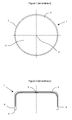
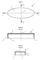
- Figures 1 and 2 illustrate a multilayer object of the prior art forming a body of revolution.
- the flow lengths are identical around the axis of symmetry.
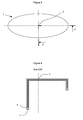
- Figures 3 and 4 illustrate a multilayer object without axis of symmetry, but having identical flow lengths around the feed center 2 of the dose.
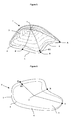
- Figure 5 illustrates the inventive concept for an object of three-dimensional geometry.
- This object without axis of symmetry comprises a central multilayer portion and at least a monolayer portion 6 located near the end 3 of the object.
- the end 4 of the multilayer structure 5 is located at a variable distance from the end 3 of the object.
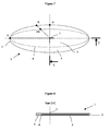
- Figure 6 illustrates the inventive concept for a flat part.
- Figures 7 and 8 show the application of the invention for a planar object of oval or elliptical geometry.
- Figures 9 to 11 illustrate a multilayer oval plug made according to the invention.
- Figures 12 to 15 illustrate a multilayer oval head of flexible tube. These figures show the modified geometry of the object so that the multilayer portion of the object is superimposed with the multilayer flexible skirt assembled by welding or overmolding.
- Figures 16 to 18 illustrate the application of the invention to multilayer square geometry heads for cardboard bricks.
- Figures 20 to 23 illustrate a molding method of guiding the flow into the mold cavity.
- the invention relates to a multilayer object not forming a body of revolution, the object being manufactured by compression molding a multilayer dose of thermoplastic resin in the molten state.
- the prior art describes objects forming bodies of revolution. These objects are characterized in that the flow length between the axis of symmetry, which is also the center of supply of the dose, and the edge forming the periphery of the object is constant. For these objects, the radial propagation of the multilayer structure during the compression of the dose is identical in all directions. The multilayer structure thus also forms a body of revolution inside the object.
- Figure 1 illustrates a multilayer object of the prior art.
- the multilayer object 1 comprises a feed center 2 corresponding to the point around which the dose is centered in the mold before compression.
- the point 2 corresponds to the intersection between the object 1 and the axis of symmetry.
- Point 2 is also the center of flow, that is, the point around which the material flows during compression.
- the end 3 of the object corresponds to the greatest distance of flow.
- the multilayer structure has a boundary 4 from which the thickness of the object is formed of only one layer.
- the outline 4 defines the multilayer portion 5 of the monolayer portion 6 of the object.
- the distance between the contours 3 and 4 is constant.
- Figure 2 shows the sectional view of the object.
- the multilayer structure forms a portion of said object that extends from the flow center to the end 4. Since the object forms a body of revolution, the flow is identical in all directions around point 2.
- the radial propagation of the multilayer structure varies according to the directions.
- the optimization of the geometry of the object and the process can not be done from the descriptions of the prior art.
- a difficulty in producing multilayer objects by compression molding is to control the propagation of the different layers and in particular to prevent trapped layers from appearing on the surface of the object. Since the flows are not identical in all directions, the control of the position of the layers in the object can not be deduced from the descriptions of the prior art.
- Another difficulty is the optimization of the geometry and the process so that the multilayer structure extends over a large part of the object.
- FIG. 4 represents a sectional view along I-direction A of the object shown in FIG. 3. As shown in FIG. 3, this object does not form a body of revolution. However, it is possible to apply for these objects the same rules as objects forming a body of revolution, because the formation and propagation of the multilayer structure during compression mainly depends on the flow and the path traveled. In this case, the path traveled is identical in all directions from the center of compression or supply of the dose, as shown by the sectional view of the object shown in Figure 4. The distance between the feeding center G and the end 3 is constant.
- An object without an axis of symmetry is compression molded with a multilayer resin dose.
- This object shown in FIG. 5 forms a shell delimited by an edge 3.
- There is not in this object a point of the shell from which the curvilinear length connecting the edge 3 is constant.
- This object has a point 2 corresponding to the feeding center of the dose.
- the flow length around point 2, i.e., the curvilinear distance R between point 2 and end 3 is variable.
- the maximum and minimum values of R are denoted respectively A and B.
- the asymmetry of the object is characterized by the ratio B / A. For the objects of the prior art, that is objects forming a body of revolution, this ratio is equal to 1.
- the objects in question in the invention have a ratio B / A less than 1 For example, this ratio is of the order of 0.5 for an oval tube head.
- the multilayer structure is delimited by an end 4, said end being generally invisible on the surface.
- the variable distance between the feed center 2 and the end 4 of the multilayer structure is denoted R1.
- the multilayer object obtained is characterized in that the distance between the ends 3 and 4 is variable around the periphery of the object and equal to (R-R1). It has been found that the distance (R-R1) between the ends 3 and 4 is minimal in the maximum flow direction; and that the distance (R-R1) was maximum in the minimum flow direction.
- the multilayer structure defines a surface S1 smaller than the surface S of the object. In order to maximize the multilayer fraction of the object, it is favorable to push the end 4 close to the end 3, without the trapped layers emerging on the surface of the object.
- the ratio S1 / S representing the multilayer fraction of the object is maximum when the end 4 joins the end 3.
- the curvilinear distance R1 between the supply center of the dose 2 and the end of the multilayer structure 4 depends on the distance R between the feed center 2 and the end of the object 3. It has been found that the ratio R1 / R is greater than or equal to B / A and less than or equal to 1. In the direction for which R is equal to A, the ratio R1 / R is maximum and can reach 1; and in the direction for which R is equal to B, the ratio R1 / R is minimal and may be equal to B / A.
- Figure 6 illustrates the inventive concept for a flat part whose geometry is not a disk.
- the radial distance R between the feeding center of the dose 3 and the end 3 of the object is not constant.
- the radial distance R1 between the feed center of the dose and the end 4 of the multilayer structure also varies according to the direction considered around the point 2.
- This object is characterized by the fact that the distance (R-R1) varies on all around the object. This distance is maximum when the distance R is equal to the minimum value B, and the distance (R-R1) is minimal when the distance R is equal to the maximum value A. It has been found that the ratio R1 / R is included between B / A and 1. It is also observed for these objects that the surface multilayer fraction S1 / S is greater than B / A.
- Figures 7 and 8 illustrate the application of the invention to the realization of a planar object whose contour forms an ellipse or an oval.
- Figure 7 shows the object seen from above; while the view 8 shows the thickness of the object according to the section CC.
- the dose is fed in 2.
- the radial flow distance around point 2 is variable. This flow distance is represented by the distance R between the end 3 of the object and the feed center of the dose 2.
- the maximum radial distance R along the largest axis of the ellipse is denoted by A, and the minimum distance R along the smallest axis of the ellipse is denoted by B.
- the object comprises a multilayer central portion denoted 5 and a monolayer peripheral portion denoted 6; the parts 5 and 6 of the object being delimited by the end 4 of the multilayer structure.
- the distance between the feeding center of the dose 2 and the end 4 is denoted R1.
- Figures 9, 10 and 11 illustrate the application of the invention to objects such as oval plugs.
- the representation of the cap is schematic, only the overall shape of the cap has been preserved for the sake of clarity of the presentation.
- Figure 9 shows the cap in top view.
- the cross-sectional views C-C and D-D illustrated in FIGS. 10 and 11 show the thickness of the object and the propagation of the multilayer structure along the major axis and along the minor axis of the oval plug.
- Figure 9 shows the feed center 2 of the dose located at the intersection of the major axis and the minor axis of the cap.
- the multilayer structure 5 forms the entire upper wall of the plug and in particular extends beyond the sealing zone with the neck of the package.
- Figure 10 shows the sectional view along the major axis.
- the end 4 of the multilayer structure has propagated in the side wall.
- Figure 11 shows the sectional view of the cap along the minor axis.
- the end 4 of the multilayer structure has not propagated in the side wall.
- This oval cap is composed of a multilayer structure 5 forming at least the upper wall, and a monolayer portion forming at least a portion of the side wall.
- the distance (R-R1) between the end 3 of the plug and the end 4 of the multilayer structure is variable.
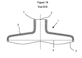
- Figures 12, 13, 14 and 15 illustrate the application of the invention to the production of flexible tube head.
- the flexible tubes consist of a molded head and a flexible skirt. The head and the skirt can be assembled by welding or overmoulding during manufacture of the head.
- Figure 12 shows the tube head in plan view. This tube head 1 of oval geometry has an orifice 7. The center of supply of the dose is located at the intersection of the major axis and the minor axis of the oval.
- Figure 13 shows the tube head in side view. The multilayer portion of the object extends to the end 4.
- the end 4 of the multilayer structure is located in the object such that the multilayer skirt assembled on said head is superimposed on the multilayer structure 5 It is interesting to note that the end 3 of the object has been modified with respect to a conventional tube head geometry in order to allow a correct distribution of the multilayer structure 5.
- FIG. 14 shows the sectional view according to FIG. large axis of the tube head.
- the end 4 of the multilayer structure 5 has spread to the level of the end 3 of the object.
- Figure 15 shows the sectional view according to the small axis. It is observed that the end 4 of the multilayer structure 5 has not propagated to the level of the end 3 of the object.
- Figures 16 to 18 illustrate the application of the invention for the realization of square packaging head. These square heads are used for "brick" type packaging. Often the sidewall associated with the head forms a multilayer structure of cardboard and thermoplastic resin. A difficulty is the production of multilayer molded heads in order to have good barrier properties. The invention can be used to produce this type of multilayer parts.
- Figure 16 shows the multilayer head seen from above. This object has an orifice 7 forming a neck and intended to extract the product from the package. The feeding center 2 of the dose is located at the intersection of the symmetry sections of the object.
- Figures 17 and 18 show two sectional views of the object. These figures make it possible to visualize the propagation of the multilayer structure in two directions.
- the multilayer structure 5 has spread in the side walls and homogeneously around the entire periphery of the object.
- the geometry of the head has been modified as indicated by the end 3 of the object.
- the end 3 of the object has been modified so that the multilayer portion 5 of the object is superimposed with the cylindrical portion assembled on the head by welding or overmolding.
- the methods described in the prior art, for making multi-layer objects by compression molding a multilayer dose consist in using a forming dose having an axis of symmetry to mold an object having an axis of symmetry. According to this method, there is an obvious geometric relationship linking the dose to the object. This method allows in particular that the creep of the material is identical in all directions. Based on this teaching, one skilled in the art would seek to use a dose without axis of symmetry to achieve objects without axis of symmetry so that the flow lengths are identical in all directions. He would seek for example to make an oval object from an oval dose.
- the method of producing a multilayer object described in the disclosure of the invention differs clearly from the prior art since it is proposed to use a dose having an axis of symmetry for to make an object without an axis of symmetry.
- an object of oval geometry is obtained from a circular dose.
- the flow lengths are no longer identical in all directions, which means that the creep of the dose is variable according to the direction of flow.
- the originality of the method consists in using an axisymmetric multilayer dose to produce an object without an axis of symmetry.
- This method consists in forming an axisymmetric multilayer dose of melt resins, feeding said dose in a mold; and then compressing said dose to create a flow and fill the cavity of said mold. During the compression of the dose, the flow of the resin layers leads to the development of a multilayer structure in the thickness of the object.
- the doses used in the context of the invention form a body of revolution. These doses described in the prior art have an axis of symmetry and are generally manufactured by continuous or discontinuous coextrusion. Many doses described in the prior art can be used. By way of example, the doses described in the patents US4876052 , JP2098415 and patent applications W02005087473 , W02005087601 , W02005084904 , W02005084903 , W02005084902 are illustrated in Figure 19. These doses comprise at least two resins 8 and 9, the resin 9 having for example a low permeability to gases or aromas. The number of resin in the dose is not limited to two. A great advantage of co-extrusion dose manufacturing is the possibility of having a large number of layers in the dose with adhesive resin layers interposed between layers of different nature.
- the compression of the dose leads to multilayer objects that can contain many layers in their thickness.
- the multilayer structure obtained during the formation of the object by compression of the dose has been widely described in US Pat. US4876052 , JP2098415 and patent applications WO2005087473 , WO2005087601 , WO2005084904 , WO2005084903 , WO2005084902 .
- the objects of the present invention differ from the objects of the art prior to the distribution of the multilayer structure, said objects having a variable distance between the end 4 of the multilayer structure and the end 3 forming the periphery of the object.
- the molding method consists in compressing an axisymmetric multilayer dose to form an object without an axis of symmetry.
- the simplest method of molding is to compress the dose by closing the mold cavity.
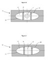
- FIGS. 20 to 23 This method is illustrated in FIGS. 20 to 23.
- FIG. 20 shows the first step of this method which consists in positioning a dose 11 in the cavity 13 of a mold 12.
- Said mold further comprises means 16 intended to separate the cavity 13 in two parts 14 and 15.
- Figure 21 illustrates the first step of compression which consists of filling the portion 14 of the cavity 13 of the mold; the means 15 preventing the flow of the dose in the portion 15 of said cavity 13.
- Figure 22 shows the dose 11 in the cavity 13 after said first compression step.
- the second step is to compress the dose 11 to fill the entire cavity 13 and form the object.
- FIG. 23 illustrates the end of the compression, when the dose 11 completely fills the cavity 11 of the
- FIGS. 20 to 22 make it possible to guide the flow of the dose during compression. It has been observed that this method makes it possible to increase the multilayer fraction of the object.
- Figures 20 to 22 show a method which consists in a first compression step to guide the flow along the minor axis of the object; then in a second step to guide the flow in the direction corresponding to the major axis of the object. This method is advantageous for increasing the multilayer fraction of the object.
- the means used to guide flow during compression are known; said means being for example moving parts of the mold. Movement of said movable portions obstructs or releases a portion of the cavity and thereby guides flow in a precise direction.
- the resins used in the context of the invention correspond to the thermoplastic resins commonly used, and more particularly those used in the packaging sector.
- the barrier resins include copolymers of ethylene vinyl alcohol (EVOH), polyamides such as nylon-MXD6, acrylonitrile methyl acrylate copolymers (BAREX), fluoropolymers such as PVDF.
- EVOH ethylene vinyl alcohol
- BAREX acrylonitrile methyl acrylate copolymers
- fluoropolymers such as PVDF.
- some resins that can be used for the layers forming the structure of the object polyethylene (PE), polypropylene (PP), polystyrene (PS), polyamide (PA), polyester (PET). This list is not exhaustive. When choosing resins, it is important to select products with similar viscosities. In general, it is preferable to use resins which at the working temperature have a viscosity ratio of less than 10, and preferably a viscosity ratio of less than 3 will be selected.
- the devices used to produce objects according to the invention are known.
- the device comprises at least means for co-extruding multilayer doses, means for transferring the multilayer dose into a compression mold, and means for compressing the dose to form the object.
- the invention has the advantage of allowing the production of multilayer objects at high production rates without significant modification compared to a device used to produce monolayer objects.
- the invention requires in particular to replace the single-layer extrusion device by a multilayer extrusion device.
Landscapes
- Engineering & Computer Science (AREA)
- Mechanical Engineering (AREA)
- Physics & Mathematics (AREA)
- Geometry (AREA)
- Manufacturing & Machinery (AREA)
- Ceramic Engineering (AREA)
- Casting Or Compression Moulding Of Plastics Or The Like (AREA)
Priority Applications (2)
| Application Number | Priority Date | Filing Date | Title |
|---|---|---|---|
| EP06110994A EP1832414A1 (de) | 2006-03-10 | 2006-03-10 | Synthetischer mehrschichtiger Gegenstand |
| PCT/IB2007/050696 WO2007105135A1 (fr) | 2006-03-10 | 2007-03-03 | Objet synthetique multicouche |
Applications Claiming Priority (1)
| Application Number | Priority Date | Filing Date | Title |
|---|---|---|---|
| EP06110994A EP1832414A1 (de) | 2006-03-10 | 2006-03-10 | Synthetischer mehrschichtiger Gegenstand |
Publications (1)
| Publication Number | Publication Date |
|---|---|
| EP1832414A1 true EP1832414A1 (de) | 2007-09-12 |
Family
ID=36781949
Family Applications (1)
| Application Number | Title | Priority Date | Filing Date |
|---|---|---|---|
| EP06110994A Withdrawn EP1832414A1 (de) | 2006-03-10 | 2006-03-10 | Synthetischer mehrschichtiger Gegenstand |
Country Status (2)
| Country | Link |
|---|---|
| EP (1) | EP1832414A1 (de) |
| WO (1) | WO2007105135A1 (de) |
Cited By (4)
| Publication number | Priority date | Publication date | Assignee | Title |
|---|---|---|---|---|
| WO2009031066A1 (fr) * | 2007-09-05 | 2009-03-12 | Aisapack Holding S.A. | Objet multicouche d'epaisseur variable |
| CN102205585A (zh) * | 2011-01-07 | 2011-10-05 | 湖南大学 | 大型薄壳结构风洞试验完全气弹模型制作方法 |
| FR2967977A1 (fr) * | 2010-11-30 | 2012-06-01 | Alsacienne De Fabrication Soc | Capsules pour flacons contenant des produits liquides ou cremeux. |
| US10688748B2 (en) * | 2013-03-14 | 2020-06-23 | Milacron Llc | Techniques to mold parts with injection-formed aperture in gate area |
Citations (5)
| Publication number | Priority date | Publication date | Assignee | Title |
|---|---|---|---|---|
| US4876052A (en) * | 1986-02-10 | 1989-10-24 | Toyo Seikan Kaisha, Ltd. | Method of extruding and compression molding a multilayered article |
| JPH0298415A (ja) * | 1988-10-06 | 1990-04-10 | Ueno Hiroshi | 多層構造圧縮成形物製造方法 |
| JPH04169207A (ja) * | 1990-11-01 | 1992-06-17 | Kurata:Kk | 樹脂成形体の製造方法 |
| JPH09216315A (ja) * | 1996-02-15 | 1997-08-19 | Kishimoto Akira | 複合合成樹脂製蓋体 |
| WO2005087601A1 (fr) * | 2004-03-01 | 2005-09-22 | Aisapack Holding S.A. | Structure multicouche |
-
2006
- 2006-03-10 EP EP06110994A patent/EP1832414A1/de not_active Withdrawn
-
2007
- 2007-03-03 WO PCT/IB2007/050696 patent/WO2007105135A1/fr not_active Ceased
Patent Citations (5)
| Publication number | Priority date | Publication date | Assignee | Title |
|---|---|---|---|---|
| US4876052A (en) * | 1986-02-10 | 1989-10-24 | Toyo Seikan Kaisha, Ltd. | Method of extruding and compression molding a multilayered article |
| JPH0298415A (ja) * | 1988-10-06 | 1990-04-10 | Ueno Hiroshi | 多層構造圧縮成形物製造方法 |
| JPH04169207A (ja) * | 1990-11-01 | 1992-06-17 | Kurata:Kk | 樹脂成形体の製造方法 |
| JPH09216315A (ja) * | 1996-02-15 | 1997-08-19 | Kishimoto Akira | 複合合成樹脂製蓋体 |
| WO2005087601A1 (fr) * | 2004-03-01 | 2005-09-22 | Aisapack Holding S.A. | Structure multicouche |
Non-Patent Citations (3)
| Title |
|---|
| PATENT ABSTRACTS OF JAPAN vol. 014, no. 305 (M - 0992) 29 June 1990 (1990-06-29) * |
| PATENT ABSTRACTS OF JAPAN vol. 016, no. 471 (M - 1318) 30 September 1992 (1992-09-30) * |
| PATENT ABSTRACTS OF JAPAN vol. 1997, no. 12 25 December 1997 (1997-12-25) * |
Cited By (5)
| Publication number | Priority date | Publication date | Assignee | Title |
|---|---|---|---|---|
| WO2009031066A1 (fr) * | 2007-09-05 | 2009-03-12 | Aisapack Holding S.A. | Objet multicouche d'epaisseur variable |
| FR2967977A1 (fr) * | 2010-11-30 | 2012-06-01 | Alsacienne De Fabrication Soc | Capsules pour flacons contenant des produits liquides ou cremeux. |
| CN102205585A (zh) * | 2011-01-07 | 2011-10-05 | 湖南大学 | 大型薄壳结构风洞试验完全气弹模型制作方法 |
| CN102205585B (zh) * | 2011-01-07 | 2013-05-08 | 湖南大学 | 大型薄壳结构风洞试验完全气弹模型制作方法 |
| US10688748B2 (en) * | 2013-03-14 | 2020-06-23 | Milacron Llc | Techniques to mold parts with injection-formed aperture in gate area |
Also Published As
| Publication number | Publication date |
|---|---|
| WO2007105135A1 (fr) | 2007-09-20 |
Similar Documents
| Publication | Publication Date | Title |
|---|---|---|
| EP2129505B1 (de) | Verfahren zur herstellung eines mehrschichtigen objekts und hergestellte objekte | |
| EP2043839A2 (de) | Durch blasformung hergestellte vorform für einen behälter | |
| EP2900453B1 (de) | Verfahren zur herstellung von rohren | |
| EP1727657B1 (de) | Verfahren zur Herstellung mehrschichtiger Kunstharzdosen | |
| WO2007105135A1 (fr) | Objet synthetique multicouche | |
| FR2872792A1 (fr) | Tubes souples legers en matiere plastique et leur procede de fabrication | |
| EP2861505B1 (de) | Rohrförmiger stumpfgeschweisster verpackungskörper | |
| WO2016097543A1 (fr) | Récipient à large col à manchon fileté rapporté | |
| EP2183087B1 (de) | Mehrschichtiges objekt mit variabler dicke | |
| EP1919680B1 (de) | Mehrschichtige objekte und herstellungsverfahren dafür | |
| WO2004030895A1 (fr) | Preforme plastique a large col avec zone d'etancheite interne protegee contre les deteriorations mecaniques | |
| FR3141371A1 (fr) | Procédé de traitement d’une structure de tête de tube et produit associé | |
| WO2004020168A2 (fr) | Procede de fabrication d’une piece en matiere plastique ayant un goulot muni d’un orifice de distribution destine a etre obture par un bouchon |
Legal Events
| Date | Code | Title | Description |
|---|---|---|---|
| PUAI | Public reference made under article 153(3) epc to a published international application that has entered the european phase |
Free format text: ORIGINAL CODE: 0009012 |
|
| AK | Designated contracting states |
Kind code of ref document: A1 Designated state(s): AT BE BG CH CY CZ DE DK EE ES FI FR GB GR HU IE IS IT LI LT LU LV MC NL PL PT RO SE SI SK TR |
|
| AX | Request for extension of the european patent |
Extension state: AL BA HR MK YU |
|
| AKX | Designation fees paid | ||
| REG | Reference to a national code |
Ref country code: DE Ref legal event code: 8566 |
|
| STAA | Information on the status of an ep patent application or granted ep patent |
Free format text: STATUS: THE APPLICATION IS DEEMED TO BE WITHDRAWN |
|
| 18D | Application deemed to be withdrawn |
Effective date: 20080323 |