EP1832420A2 - Dispositif de pliagede doté d'appareils de pliage à différentes hauteurs - Google Patents
Dispositif de pliagede doté d'appareils de pliage à différentes hauteurs Download PDFInfo
- Publication number
- EP1832420A2 EP1832420A2 EP07103537A EP07103537A EP1832420A2 EP 1832420 A2 EP1832420 A2 EP 1832420A2 EP 07103537 A EP07103537 A EP 07103537A EP 07103537 A EP07103537 A EP 07103537A EP 1832420 A2 EP1832420 A2 EP 1832420A2
- Authority
- EP
- European Patent Office
- Prior art keywords
- folding
- printing
- folding device
- cylinder
- cutting
- Prior art date
- Legal status (The legal status is an assumption and is not a legal conclusion. Google has not performed a legal analysis and makes no representation as to the accuracy of the status listed.)
- Withdrawn
Links
Images


Classifications
-
- B—PERFORMING OPERATIONS; TRANSPORTING
- B41—PRINTING; LINING MACHINES; TYPEWRITERS; STAMPS
- B41F—PRINTING MACHINES OR PRESSES
- B41F13/00—Common details of rotary presses or machines
- B41F13/54—Auxiliary folding, cutting, collecting or depositing of sheets or webs
- B41F13/56—Folding or cutting
- B41F13/60—Folding or cutting crosswise
Definitions
- the invention relates to a folding device with folders arranged at different heights and to a rotary printing press comprising such a folding device.
- the invention can be realized in particular in web-fed rotary printing, preferably in offset printing and particularly preferably in newspaper printing.
- the folders are depending on the requirementssanfordeiungen and the associated web paths either at a front end or in a central area of the printing press.
- double folding apparatus For a flexible production change between large runs and split several smaller editions, the construction of so-called double folding apparatus has proven economically. Double-folding machines were even used to divide the copy stream of a production into two half-power copies. If this division served in former times to be able to cope with the partial manual or mechanical removal of printed copies, these so-called split displays soon gave way to the actual synchronous double displays with increasing efficiency of the forwarding installations. H. laying out two different productions at the same speed.
- the problem is solved by means of a folding device comprising at least two folders, one of which is arranged above the other and to this preferably with a lateral offset.
- the folding device therefore comprises a lower folding apparatus and an upper folding apparatus, which is arranged above the lower folding apparatus and this at least partially, preferably only partially covered. Due to the arrangement of the upper folder above the lower footprint is saved.
- the folding device indeed requires more footprint than in the case of a full coverage, on the other hand can be created by the offset and thereby only partially overlap a disability-free enema in the lower folder.
- the upper folder has an upper quill cutting device for cross-cutting a first print product web into printed products, ie printed copies, and an upper folding cylinder for cross-folding the printed products.
- the lower folding apparatus accordingly comprises a lower transverse cutting device for cross-cutting a second printed product web into further printed products and a lower folding cylinder for transverse folding of the further printed products.
- the folders should have an offset from one another in a direction transverse to the axis of rotation of one of the folding cylinders, preferably only in this direction, and be arranged in the axial direction of the respective folding cylinder at least substantially vertically in alignment one above the other.
- the two folders are preferably offset from one another so far that the second printed product web can be conveyed past the upper folder by a short path into the lower cross-cutter. This is possible in particular when the second printed product web is conveyable parallel to the first printed product web in the lower transverse cutting device parallel to the first printed product web and after its entry into the upper cross-cutting direction when conveyed vertically. This does not mean that the second print product web must be required in all circumstances just vertically past the upper folder or the first print product web vertically into the upper cross cutter, although such conveyance is preferred to provide the shortest possible print paths for the transverse fold to demand the respective folder.
- the second printed product web in the case of a smaller or non-existent offset before entering the lower cross-cutting device to be deflected towards this again to guide them past the upper folder.
- the offset should be as small as possible, so that the folding device takes up as little floor space.
- An offset, which makes the web guide described as being preferred, is therefore particularly preferred.
- the folding device can be arranged in a printing machine with a plurality of printing towers arranged next to one another at one end of the printing tower row. More preferably, however, it is located in a central area of the printing press between two printing towers so that printed product webs can be conveyed from two sides to the folding device.
- the folders may basically be set up so that the axis of rotation of the upper folding cylinder is inclined to the axis of rotation of the lower folding cylinder, it is preferred that the folders have the same orientation, i. H. when the axes of rotation of their folding cylinders are parallel to each other.
- the folders are preferably oriented so that they lay the transversely folded printed products on the same page.
- the upper folder is arranged in preferred embodiments not only on but on the lower folder, d. H. it rests directly on a frame, preferably the side walls of the lower folder.
- a storage table or other support means for the upper folder is saved.
- the height of the folding device is reduced to a minimum.
- the lower folder may be arranged together with roll changer on a bottom of a roll tray.
- the upper folder can stand together with the printing units on a plant-forming ceiling above the roll cell, so that the ceiling forms the above-mentioned support means. More preferably, however, the upper folder rests on the lower folder as stated.
- the arrangement of the lower folding apparatus in the roller cellar allows the arrangement of the upper folding apparatus at advantageously low level, on the other hand impairs a standing in the roll cell on reel changer folding folder, however, the logistics in the roll cell, at least in the case of the arrangement of the folding device in the central area of the printing press.
- the lower folder is therefore preferably above the bottom of the roll cellar, either on a false ceiling or on the Plant level on which the printing units are supported.
- the roll changers may also be installed at the plant level.
- the false ceiling on which the lower folder is placed lifted from the basement floor, has a clear distance from the basement floor, which is preferably so large that a web roll between the basement floor and the false ceiling can be transported through.
- the false ceiling can be suspended from a ceiling forming the plant level or formed by a storage table. Preference is given to a combination of suspended ceiling and support of the false ceiling on support elements, such as columns.
- the folding device also comprises a longitudinal folding device for longitudinal folding of the printed product webs.
- the Lssensfalz preferably comprises a plurality of juxtaposed at the same height former. It may also comprise a balloon funnel arrangement, i. H. arranged at different heights funnel. In a preferred variant, it comprises or consists of three seam tails (n), which are arranged side by side at the same height, and three further (n) Former (n), which are also arranged next to each other at a different height, preferably over the first three funnels mentioned , To save room height, a preferred other variant provides the arrangement of formers only at the same height next to each other, wherein the number of funnels is preferably greater than the number of printable double pages in the printing units.
- the folding device for example, for a printing press which prints four pages wide or is installed in such a machine, preferably at least three, particularly preferably exactly three, three folding formers are arranged side by side at the same height.
- three folding formers are arranged side by side at the same height.
- four folding hoppers are arranged side by side at the same height.
- the invention relates not only to a folding device as such, which may be provided, for example, only for installation in a printing press, but also a Druclanaschine with a folding device according to the invention.
- the printing press is preferably a rotary printing press, particularly preferably a web-fed rotary printing press.
- the rotary printing machine comprises the already mentioned several times printing units with printing cylinders that form pressure gaps for multiple webs.
- the printing units may in particular satellite printing units, for example, 9- or 10-cylinder units, or so be mentioned rubber / rubber printing units.
- Preferred printing units and drives for such printing units are in the EP 0 644 048 A1 described in this regard.
- the folding device is preferably driven by its own drive. Particularly preferably, each of the folders is equipped with its own drive. Preferred drives for folders are in the EP 0 741 019 A1 described in this regard.
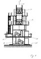
- Figures 1 and 2 show a web-fed rotary printing press with a folding device in a first embodiment.
- Figure 1 shows a view of the folding device in the longitudinal direction of the printing press.
- FIG. 2 shows a central area of the printing press in a side view.
- the printing press comprises a plurality of printing towers, each having a plurality of printing units 30 each comprising a transfer cylinder, a forme cylinder and associated inking units, and preferably also associated dampening units for offset printing, preferably wet offset printing.
- the printing units 30 form four printing gaps per printing tower for double-sided printing on both sides. Within the printing towers, the printing units 30 are arranged in so-called H printing units.
- the printing towers could also be designed as ten or twelve towers, ie have five or six pressure gaps on top of each other.
- extended printing towers can be particularly flexible from one production to the other, by conveying the web through more pressure gaps in one production than actually used for production.
- the transfer cylinders of the previously unused printing nip or the previously unused printing nip can be delivered and the transfer cylinders of a printing nip previously used for the printing or of previously used printing nips are turned off from each other.
- Such flexibility with regard to the conversion from one production to the other as the web continues to run can also be obtained in the same way with satellite printing works.
- At least one further printing tower is arranged in each case in the longitudinal direction Y of the printing press, which can be formed in particular like the two illustrated printing towers as a four-high tower or alternatively as a ten or twelve tower.
- the neighboring printing towers can also have printing units in satellite construction or consist of such.
- a device 31 for merging printed webs is disposed above the two central printing towers.
- the devices 31 are turning bar devices.
- a folding device with two folders 1 and 11 is arranged for the transverse folding of printed products.
- the folders 1 and 11 are arranged vertically one above the other, wherein the lower folding apparatus 11, d. H. a frame of the lower folding apparatus 11, the upper folding apparatus 1 is supported.
- the folders 1 and 11 are thus stacked on each other.
- two L jossfalz coupleden 23 are arranged, which as Figure 1 shows, are designed as a so-called balloon funnel arrangement, each with three at the same height juxtaposed formers.
- the folding device 1, 11, the folding structure and the folding superstructure including the longitudinal folding means 23 is placed on a false ceiling 27.
- the false ceiling 27 is a mounting plane which is vertically retracted between a floor 25 forming a reel changer level of a roller basement and a ceiling 26.
- the ceiling 27 forms the plant level on which the printing towers stand.
- On the floor 25 of the roller basement are several reel changer, preferably a paster, per printing tower.
- the false ceiling 27 is suspended from the ceiling 26 forming the installation level and is additionally supported by support elements 28, in the exemplary embodiments support columns.
- the vertical clear distance between the bottom 25 of the roller basement and the false ceiling 27 has slightly more than man height on.
- the support elements 28 are spaced so far apart that web rolls between the support elements 28 can be transported through, preferably both in the direction parallel to the axes of rotation of the printing cylinder X-direction and in the longitudinal direction Y of the printing press.
- FIG. 1 shows, the folders 1 and 1 are arranged offset to one another in the X direction.
- FIG. 2 shows that there is no offset with respect to the Y-direction, but rather that the folding apparatuses 1 and 11, in particular their cylinders, are aligned vertically exactly with respect to the Y-direction.
- the upper folding apparatus 1 comprises a cross-cutting device consisting of a cutting cylinder 2 and a collecting cylinder 3, further comprising a folding cylinder 4, a paddle wheel 5 and a delivery 6 in the form of a belt delivery.
- the corresponding components of the lower folding apparatus 11 are provided with the reference numbers increased by the number 10. A difference exists only with respect to the display 16, which is extended in relation to the upper display 6 in accordance with the offset.
- the folding cylinders 4 and 14 may in particular be jaw cylinders. Alternatively, however, they may be formed as rotating folding cylinders and the folders 1 and 11 accordingly as rotating folders. Also advantageous is the combination of a Klappenfalzapparat and a rotating folder.
- the axes of rotation of the cylinders of the folders 1 and 11 have at right angles to the axes of rotation of the printing cylinder, the cross-cut printed products are therefore conveyed to the web plane in the towers at right angles through the folders 1 and 11.
- the folders 1 and 11 set to the same page.
- the cross-sectional means 2, 3 and 12, 13 each form a gap into which enters the respectively associated print product web B1 or B2.
- the upper folding apparatus 1 is offset to the side of the displays 6 and 16 relative to the lower folding apparatus 11 so far that the printed product web B2 next to the upper folding apparatus 1 vertically downwards in a straight path in the gap of the lower transverse cutting device 12, 13 can be promoted.
- the offset of the folders 1 and 11 is accordingly between the inlet gap of the upper Querschneidcin therapies 2, 3 and the inlet gap of the lower Querschncid issued 12, 13 measured.
- the offset should be as small as possible in order to keep the required footprint in the X-direction, ie, parallel to the axes of rotation of the printing cylinders, as short as possible.
- the offset should therefore be so small that the inlet gap of the upper cross-cutting device 2, 3 is at least still in register with the lower folding cylinder 14 or possibly even in overlap with the lower collecting cylinder 13.
- Optimal is an offset in which the upper collecting cylinder 3 is to a greater extent preferably to a predominant part, still in a vertical overlap with the lower folding cylinder 14, as Figure 1 shows this by way of example.
- the two folders 1 and 11 are each about the same length to one in the -X direction and the other are offset in the + direction with respect to each exactly centered arrangement.
- Each of the folders 1 and 2 is thus offset by at least substantially the same length relative to an exactly central arrangement. Particularly favorable conditions arise when the axis of rotation of the upper collecting cylinder 3 to the side of the upper delivery 6 a small piece next to the central vertical axis Z and the axis of rotation of the lower folding cylinder 14 to the other side a small piece next to the central vertical axis Z come to rest. These two cylinders 3 and 4 will thus not cover completely in the case of the same diameter, but only to a greater extent.
- the folding device 1, 11 further comprises a Whodeck 29, which is designed as an intermediate deck and rests on the lower folding apparatus 11.
- the upper folder 1 stands on the Whydeck 29.
- the Whodeck 29 is exposed, i. architecturally unsupported. Alternatively, it would also be possible not to support the Whydeck 29 by the printing press, in particular not by the folding apparatus 11, but otherwise structurally.
- the movable components of the folders 1 and 11 are supported by stable side walls 7 and 17.
- the side wall 17 of the lower folding apparatus 11 is extended to support the upper folding apparatus 1 to the side of the display 16 out to a support wall 18.
- the side wall 7 of the upper folding apparatus 1 is extended to the other side, in the region of the continuous print product web B2 to an intermediate wall 8, however, no comparable supporting function, but primarily only the function of storage of guide rollers, such as pull rollers, for the printed product web B2 takes over.
- Figure 3 shows a folding device of a second embodiment in a view in the longitudinal direction Y of the printing machine.
- the folding device 1, 11 of the second embodiment corresponds to the folding apparatuses 1 and 11 of those of the first embodiment.
- the statements made with regard to the first exemplary embodiment for lateral offset apply.
- the folders 1 and 11 and their components are accordingly provided with the same reference numerals. Differences exist only with regard to the installation of the folding device 1, 11 overall and the longitudinal folding device, which is provided in the second embodiment for differentiation by the reference numeral 33.
- the folding device 1, 11 of the second embodiment does not rest on a false ceiling, but together with the printing units 30 on the abutment plane forming ceiling 26.
- the folders 1 and 11 of the second embodiment accordingly take relative to the printing units .30 Higher vertical positions than the folders. 1 and 11 of the first embodiment.
- the Leksfalz coupled 33 includes only former, which are arranged at the same height next to each other.
- the Leksfalz coupled 33 consists of four juxtaposed formers.
- a second funnel level does not exist.
- the machine is preferably a six-page printing machine. In order to be able to fold the resulting three double pages in a booklet, basically only three of the funnels are needed.
- the fourth hopper allows for the formation of a fourth booklet, which is advantageous especially for productions with large page number per page printed product.
- the formation of a fourth booklet can reduce the volume of individual booklets or the volume of a thickest booklet.
- the respective, longitudinally cut web strands need only be turned on the fourth funnel accordingly.
- the four longitudinally folded booklets or even only a part of the four longitudinally folded booklets can be split as shown by way of example in FIG. 3 behind the formers and fed as the printing product bellows B 1 and B2 to the downstream folders 1 and 11.
- two identical or unequal print product webs B1 and B2 and correspondingly identical or unequal printed products can be produced in this way.
- FIG. 4 shows a third variant of the two folders 1 and 11.
- the lower folder 11 stands on the base 25 of the roller cellar forming the roller leveler
- the upper folder 1 stands on the ceiling 26 forming the contact surface
Landscapes
- Engineering & Computer Science (AREA)
- Mechanical Engineering (AREA)
- Folding Of Thin Sheet-Like Materials, Special Discharging Devices, And Others (AREA)
Applications Claiming Priority (1)
| Application Number | Priority Date | Filing Date | Title |
|---|---|---|---|
| DE102006010602A DE102006010602A1 (de) | 2006-03-06 | 2006-03-06 | Falzvorrichtung mit auf unterschiedlichen Höhen angeordneten Falzapparaten |
Publications (2)
| Publication Number | Publication Date |
|---|---|
| EP1832420A2 true EP1832420A2 (fr) | 2007-09-12 |
| EP1832420A3 EP1832420A3 (fr) | 2009-10-21 |
Family
ID=38171272
Family Applications (1)
| Application Number | Title | Priority Date | Filing Date |
|---|---|---|---|
| EP07103537A Withdrawn EP1832420A3 (fr) | 2006-03-06 | 2007-03-05 | Dispositif de pliagede doté d'appareils de pliage à différentes hauteurs |
Country Status (3)
| Country | Link |
|---|---|
| US (1) | US20080011169A1 (fr) |
| EP (1) | EP1832420A3 (fr) |
| DE (1) | DE102006010602A1 (fr) |
Families Citing this family (2)
| Publication number | Priority date | Publication date | Assignee | Title |
|---|---|---|---|---|
| DE102008054831B4 (de) * | 2008-12-17 | 2016-05-19 | Manroland Web Systems Gmbh | Falzaufbau einer Rollendruckmaschine |
| KR20160065504A (ko) * | 2014-12-01 | 2016-06-09 | 엘지전자 주식회사 | 멀티미디어 디바이스 및 그 제어 방법 |
Citations (2)
| Publication number | Priority date | Publication date | Assignee | Title |
|---|---|---|---|---|
| EP0107126A1 (fr) | 1982-10-09 | 1984-05-02 | Koenig & Bauer Aktiengesellschaft | Dispositif de guidage de la bande de papier dans une rotative d'impression |
| DE10106985A1 (de) | 2001-02-15 | 2002-08-29 | Roland Man Druckmasch | Falzapparat für stehende und liegende Produktion |
Family Cites Families (10)
| Publication number | Priority date | Publication date | Assignee | Title |
|---|---|---|---|---|
| DE59410108D1 (de) * | 1993-12-29 | 2002-05-23 | Wifag Maschf | Rotationsdruckmaschine |
| WO1996029204A1 (fr) * | 1995-03-18 | 1996-09-26 | Koenig & Bauer-Albert Ag | Procede d'actionnement d'une unite, par ex. une plieuse de presse rotative |
| DE19516445A1 (de) * | 1995-05-04 | 1996-11-07 | Wifag Maschf | Rotationsdruckmaschine mit frei aufstellbarem Falzapparat |
| DE19516443A1 (de) * | 1995-05-04 | 1996-11-07 | Wifag Maschf | Einzeln angetriebener Falzapparat für eine Rotationsdruckmaschine |
| FR2759995B1 (fr) * | 1997-02-26 | 1999-11-26 | Heidelberg Harris Sa | Plieuse d'une machine rotative a imprimer |
| DE19856422C2 (de) * | 1998-12-08 | 2001-11-08 | Koenig & Bauer Ag | Warenbahnzuführung zu einem Falzwerk |
| DE19959152A1 (de) * | 1999-12-08 | 2001-06-13 | Heidelberger Druckmasch Ag | Einrichtung zur Führung von Materialbahnen in Rotationsdruckmaschinen |
| WO2003031181A1 (fr) * | 2001-10-05 | 2003-04-17 | Koenig & Bauer Aktiengesellschaft | Dispositif de traitement d'une bande, element de pliage d'une presse rotative a imprimer et presse rotative a imprimer |
| DE10238010B4 (de) * | 2002-08-20 | 2006-04-13 | Man Roland Druckmaschinen Ag | Falzeinheit für Rollenrotationsdruckmaschinen mit kombinierter Zeitungs- und Selected Commercial-Produktion |
| EP1644191B1 (fr) * | 2003-07-11 | 2009-02-18 | Koenig & Bauer Aktiengesellschaft | Machine d'impression rotative a bobines |
-
2006
- 2006-03-06 DE DE102006010602A patent/DE102006010602A1/de not_active Ceased
-
2007
- 2007-03-05 EP EP07103537A patent/EP1832420A3/fr not_active Withdrawn
- 2007-03-06 US US11/714,674 patent/US20080011169A1/en not_active Abandoned
Patent Citations (2)
| Publication number | Priority date | Publication date | Assignee | Title |
|---|---|---|---|---|
| EP0107126A1 (fr) | 1982-10-09 | 1984-05-02 | Koenig & Bauer Aktiengesellschaft | Dispositif de guidage de la bande de papier dans une rotative d'impression |
| DE10106985A1 (de) | 2001-02-15 | 2002-08-29 | Roland Man Druckmasch | Falzapparat für stehende und liegende Produktion |
Also Published As
| Publication number | Publication date |
|---|---|
| DE102006010602A1 (de) | 2007-09-20 |
| EP1832420A3 (fr) | 2009-10-21 |
| US20080011169A1 (en) | 2008-01-17 |
Similar Documents
| Publication | Publication Date | Title |
|---|---|---|
| EP1742796A1 (fr) | Presses rotatives a imprimer | |
| DE10236864B4 (de) | Heatset-Druckmaschine | |
| EP1999051B1 (fr) | Dispositifs et procédé d'acheminement une bande de matière à une unité d'impression d'une rotative d'imprimerie | |
| DE19728207A1 (de) | Wendeturmanordnung | |
| EP1590283B1 (fr) | Machine a imprimer comprenant au moins un groupe d'impression, un appareil de pliage et au moins un niveau de retournement et de melange | |
| EP1742794A1 (fr) | Formes d'impression d'une machine d'impression, et presse rotative a imprimer | |
| DE102007047842B3 (de) | Druckwerk und Druckmaschine | |
| DE102007032831A1 (de) | Druckmaschine, Druckmaschinenanlage sowie Verfahren zur Verwendung der Druckmaschinenanlage bzw. der Druckmaschine | |
| EP1742793A1 (fr) | Groupe d'impression offset d'une imprimeuse destinee a l'impression de journaux | |
| EP2193918B1 (fr) | Agencement de cône plieur | |
| EP1832420A2 (fr) | Dispositif de pliagede doté d'appareils de pliage à différentes hauteurs | |
| EP2223806A1 (fr) | Dispositif et procédé d'écartement de bandes se déroulant dans le sens transversal par rapport à l'axe longitudinal d'une presse d'impression rotative | |
| EP1839855A2 (fr) | Dispositif et procédé destinés à l'introduction d'une bande dans un dispositif de traitement de bandes | |
| WO2006000527A1 (fr) | Presse rotative a imprimer a barre de retournement | |
| EP1615773B1 (fr) | Procede permettant de generer un produit d'impression | |
| DE10163211C2 (de) | Vorrichtung zur Herstellung von Falzprodukten | |
| DE102006013954B4 (de) | Druckmaschine mit einer Einrichtung zum Zuführen einer Materialbahn | |
| DE102008042085B4 (de) | Verfahren und Vorrichtung zum Führen von Bahnen in einer Rollenrotationsdruckmaschine | |
| EP2014595B1 (fr) | Presse, installation de presse et procédé de fonctionnement d'une presse ou d'une installation de presse | |
| EP2344335B1 (fr) | Imprimeuse et procédé avec unité de retournement | |
| DE102011088780B4 (de) | Rollen-Rotationsdruckmaschine | |
| DE102016124332A1 (de) | Rotationsdruckmaschine |
Legal Events
| Date | Code | Title | Description |
|---|---|---|---|
| PUAI | Public reference made under article 153(3) epc to a published international application that has entered the european phase |
Free format text: ORIGINAL CODE: 0009012 |
|
| AK | Designated contracting states |
Kind code of ref document: A2 Designated state(s): AT BE BG CH CY CZ DE DK EE ES FI FR GB GR HU IE IS IT LI LT LU LV MC MT NL PL PT RO SE SI SK TR |
|
| AX | Request for extension of the european patent |
Extension state: AL BA HR MK YU |
|
| PUAL | Search report despatched |
Free format text: ORIGINAL CODE: 0009013 |
|
| AK | Designated contracting states |
Kind code of ref document: A3 Designated state(s): AT BE BG CH CY CZ DE DK EE ES FI FR GB GR HU IE IS IT LI LT LU LV MC MT NL PL PT RO SE SI SK TR |
|
| AX | Request for extension of the european patent |
Extension state: AL BA HR MK RS |
|
| 17P | Request for examination filed |
Effective date: 20100112 |
|
| AKX | Designation fees paid |
Designated state(s): AT BE BG CH CY CZ DE DK EE ES FI FR GB GR HU IE IS IT LI LT LU LV MC MT NL PL PT RO SE SI SK TR |
|
| STAA | Information on the status of an ep patent application or granted ep patent |
Free format text: STATUS: THE APPLICATION IS DEEMED TO BE WITHDRAWN |
|
| 18D | Application deemed to be withdrawn |
Effective date: 20121002 |