EP1832452B1 - Dispositif d'écoulement d'air avec rétrosignal visuel - Google Patents
Dispositif d'écoulement d'air avec rétrosignal visuel Download PDFInfo
- Publication number
- EP1832452B1 EP1832452B1 EP07003538A EP07003538A EP1832452B1 EP 1832452 B1 EP1832452 B1 EP 1832452B1 EP 07003538 A EP07003538 A EP 07003538A EP 07003538 A EP07003538 A EP 07003538A EP 1832452 B1 EP1832452 B1 EP 1832452B1
- Authority
- EP
- European Patent Office
- Prior art keywords
- light
- air outlet
- component
- axis
- air
- Prior art date
- Legal status (The legal status is an assumption and is not a legal conclusion. Google has not performed a legal analysis and makes no representation as to the accuracy of the status listed.)
- Not-in-force
Links
Images


Classifications
-
- B—PERFORMING OPERATIONS; TRANSPORTING
- B60—VEHICLES IN GENERAL
- B60H—ARRANGEMENTS OF HEATING, COOLING, VENTILATING OR OTHER AIR-TREATING DEVICES SPECIALLY ADAPTED FOR PASSENGER OR GOODS SPACES OF VEHICLES
- B60H1/00—Heating, cooling or ventilating devices
- B60H1/34—Nozzles; Air-diffusers
-
- B—PERFORMING OPERATIONS; TRANSPORTING
- B60—VEHICLES IN GENERAL
- B60Q—ARRANGEMENT OF SIGNALLING OR LIGHTING DEVICES, THE MOUNTING OR SUPPORTING THEREOF OR CIRCUITS THEREFOR, FOR VEHICLES IN GENERAL
- B60Q3/00—Arrangement of lighting devices for vehicle interiors; Lighting devices specially adapted for vehicle interiors
- B60Q3/20—Arrangement of lighting devices for vehicle interiors; Lighting devices specially adapted for vehicle interiors for lighting specific fittings of passenger or driving compartments; mounted on specific fittings of passenger or driving compartments
-
- B—PERFORMING OPERATIONS; TRANSPORTING
- B60—VEHICLES IN GENERAL
- B60Q—ARRANGEMENT OF SIGNALLING OR LIGHTING DEVICES, THE MOUNTING OR SUPPORTING THEREOF OR CIRCUITS THEREFOR, FOR VEHICLES IN GENERAL
- B60Q3/00—Arrangement of lighting devices for vehicle interiors; Lighting devices specially adapted for vehicle interiors
- B60Q3/60—Arrangement of lighting devices for vehicle interiors; Lighting devices specially adapted for vehicle interiors characterised by optical aspects
- B60Q3/62—Arrangement of lighting devices for vehicle interiors; Lighting devices specially adapted for vehicle interiors characterised by optical aspects using light guides
- B60Q3/64—Arrangement of lighting devices for vehicle interiors; Lighting devices specially adapted for vehicle interiors characterised by optical aspects using light guides for a single lighting device
Definitions
- the invention relates to an air vent, in particular for a motor vehicle, which allows a visual assessment of its operating state even in low ambient light.
- Air vents in motor vehicles usually have devices for regulating operating states, such as the amount of air flowing out, the direction of the air flow and possibly the flow characteristics.
- Such a Heilausströmer is from the DE 10 2004 038 016 A1 known. With sufficient lighting, z.
- the set operating conditions of a driver of the motor vehicle are usually to capture at a glance and can be just as uncomplicated and intuitive.
- checking and adjusting these devices requires a higher level of attention, as the air vents and the more the devices are poorly visible. Solutions that partially chromed or chromated these devices do not solve the problem.
- the air vent according to the invention comprises at least one component which is visible from a space to be ventilated by the air vent and can be wetted by an air stream which can be flowed through the air vent.
- the device is at least partially formed of a photoconductive material and it can be fed to him light. When light is supplied to the component, at least the parts formed of the photoconductive material are visible from the room to be ventilated even in the dark, so that a driver of a motor vehicle whose interior is ventilated can easily find out about set operating states of the air vent can. Due to the luminous component, only a small part of the driver's attention is required for this, so that traffic safety remains unimpaired.
- the component is designed as an air duct, in particular for a direct, jet-shaped air outlet.
- the driver can control and optionally adjust in which direction the airflow exits.
- the air duct is formed as an elongated hollow body with open ends and an axis oriented in the normal direction to a longitudinal axis of symmetry (also called air duct axis) and is pivotable about this axis, so that pivoting of the air duct, the direction of the air flow changes.
- a longitudinal axis of symmetry also called air duct axis
- the axis is a part of the air duct in order not to hinder the light conduction between the axis and the air duct, since the axis is particularly suitable for coupling the light into the air duct.
- the air vent has a device for influencing the direction of the air flow on a side of the air vent facing the space to be ventilated, which influences the direction of the air flow by means of at least one slat, in particular in the vertical direction.
- the lamella is designed as a component photoconductive, so that the driver receives a simple control option for this direction of the air flow.
- This lamella preferably has a longitudinally arranged axis (also called lamellar axis) about which it is pivotable. Such an axle provides easy pivoting.
- the axis is particularly suitable for coupling in the light. In the interest of a low-loss light pipe, the axis is a component of the lamella.
- the light is supplied to the device at an end face of at least one end of an axis (e.g., the fin axis or the air passage axis), there is no need to connect a light source or a light transmitting medium to the device so as to follow its movements and be subject to wear.
- an axis e.g., the fin axis or the air passage axis
- the light is supplied to the device via another surface of at least one end of the axis, e.g. with cylindrical axes over the cylindrical surface.
- an at least partially photoconductive bearing element which in turn can be supplied with light
- a plurality of slats a plurality of bearings corresponding to the number of slats are expediently provided in the bearing element.
- a suitable mechanism ensures synchronous pivoting of all slats as soon as a single slat is swiveled.
- the lamellae can also be pivoted asynchronously by means of a suitable adjusting mechanism.
- a light-conducting Reiterverstellknopf is arranged longitudinally displaceable on a blade as a component to which light from this slat can be fed.
- a Reiterverstellknopf serves to actuate an adjustment kinematics, such as a linkage, which in turn causes a pivoting of the air duct.
- an adjustment kinematics such as a linkage
- the horizontal pivoting direction of the air flow can be visualized alternatively or additionally.
- additional, ie redundant, information is cognitively advantageous because it allows the driver to grasp the situation more quickly.
- Reiterverstellnopfs can be used as lichleitfixedes component for adjustment and a joystick, a ball adjustment knob, a lever mechanism, an adjusting or the like are used, which are preferably arranged outside the Heilausströmers or the air duct.
- the supply of light into the component and / or the bearing element is effected by a light source attached thereto and / or by a housing in which the light source is arranged.
- the housing for this purpose has a photoconductive prism, e.g. plastic, on.
- the component and / or the bearing element have a complementary to this prism plug-in device to accommodate the prism can.
- the component and / or the bearing element light from an optical fiber can be supplied, in turn, the light from the light source can be coupled. In this way, an air vent with a complicated geometry and many components to be illuminated with only one light source can be operated.
- the light source is designed as a light emitting diode (LED).
- LED light emitting diode
- the low power consumption of a light emitting diode is advantageous for both economic reasons and because of the consequently low heat output.
- the photoconductive material is at least partially colored. In this way, the visual impression can be easily adapted even with a white light source.
- the component and / or the bearing element is at least partially painted with an opaque paint, so that light exits only at the non-painted locations of the component and / or the bearing element.
- the bearing element it can be ensured that the light exits only at the bearing points for the axes, when all other areas, except for the point at which the light is coupled, are painted.
- the component only the ends of the axes used for coupling in light and the parts intended for lighting are accordingly not painted.
- the Reiterverstellknopfes the lamella in the area on which the Reiterverstellknopf is arranged longitudinally displaceable, must have a non-painted surface.
- the Reiterverstellknopf needs a matching, unpainted surface in order to couple the light from the slat can. With sufficient illumination, the component no light is supplied and it appears in the color of the opaque paint.
- the same effect is more easily achievable if the opaque paint is removed from the device at at least one selected location.
- the component could first be painted completely and then the paint partially removed according to the design specifications, e.g. by means of a laser.
- the component and / or the bearing element contains at least one opaque material component, so that it is composed of at least two components, a photoconductive and an opaque.
- the device can be designed in this way so that it shines only in places and directs light, which are formed from the photoconductive component, so as to achieve a desired appearance.
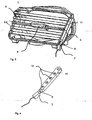
- a device 4 for influencing a direction of an air flow is provided which is provided with slats 5.
- a Reiterverstellknopf 6 is arranged longitudinally displaceable, which serves to actuate a Verstellkinematik not shown for changing the direction of the air flow.
- a light source in particular a light-emitting diode, is arranged in a housing 7 with a prism 8. For receiving this housing 7, the lower part of the axis 3.1 at its end face on a plug-in device 9, which is complementary to the housing 7 is formed.
- the air ducts 2 are pivotable about their axes 3.1, so that the direction of the air flow in the horizontal direction can be influenced.
- the actuation takes place with the Reiterverstellknopf 6.
- the housing 7 is inserted once for better illustration in the plug-in device 9 and once shown separately
- Fig. 2 is an air duct 2 from the in Fig. 1 shown Heilausströmer shown, which is particularly suitable for the outflow of a direct, jet-shaped air flow.
- the air channel 2 and the axis 3.1 are formed of a photoconductive material and coated with an opaque paint, which was selectively removed at the plug-in device 9 and at the front edge 10 of the air channel 2 with a laser, so that only the luminous edge 10 of the air channel 2 is perceived by a driver of a motor vehicle in which the air vent 1 is arranged.
- the axis 3.1 is not continuous, but mounted in the manner of half-axes at the top and bottom of the air duct 2. A consistent design would also be possible.
- a further embodiment of a Lucasausströmers 1 is shown, which has on the side facing the space to be ventilated of the Lucasausströmers 1 a device 4 for influencing the direction of the air flow, which is provided with fins 5.
- a suitable mechanism not shown here, it is achieved that the pivoting of a lamella 5 causes a synchronous pivoting of all the other lamellae 5.
- On one of the slats 5 is a Reiterverstellknopf 6 for operating another device, in particular one in Fig. 1 and Fig. 2 shown air duct, arranged longitudinally displaceable.
- the axles 3.2 of the lamellae 5 are mounted in a bearing element 11, which has a plug-in device 9 concealed here for receiving a housing 7 provided with a prism 8 of a light source.
- the insertion device 9 is shaped to be complementary to the shape of the housing 7.
- the bearing element 11, the slats 5, the axes connected integrally with the slats 5 3.2 and the Reiterverstettknopf 6 are made of a photoconductive material and painted with an opaque lacquer. This is located at the points provided for the light exit and in the areas required for the light transmission between the individual parts areas, for example by means of a laser.
- Fig. 4 is a bearing element 11, as in the air vent 1 from Fig. 3 is used, shown from a different perspective, so that the bearings 12, in which the axes can be stored 3.2 of the fins 5, visible.
- the housing 7 provided with a prism 8 of the light source is shown in the position in which it can be inserted into the insertion device 9.
- the bearing element 11 is made of rindleitJem material and painted with an opaque lacquer. At the plug-in device 9 and at the bearings 12, the paint was removed with a laser to allow entry and exit of the light.
- Fig. 5 shows a blade 5, as in an air vent 1 from Fig. 3 is used.
- the lamella 5 is formed of a photoconductive material and painted with an opaque lacquer.
- the lacquer is removed by means of a laser.
- Light can be coupled into the lateral surface and / or end face of the axle 5 from the bearing 12 of the bearing element 11.
- the arrangement of a Reiterverstellknopfes 6 is provided, which can be lekssverschofben within the adjustment range 13 on the lamella 5.
- the lamella 5 must have a surface which is not covered with the opaque paint.
- Fig. 3 visible, formed of photoconductive material and coated with an opaque lacquer Reiterverstellknopf 6 has on its complementary to the shape of the lamella 5 formed, not shown back, also a surface which is not covered with the opaque lacquer, so that light from the lamella. 5 can be coupled into the Reiterverstellknopf 6.
- the paint on the room to be ventilated facing side of the Reiterverstellknopfes 6 locally removed to allow the design specifications corresponding light output.
- the light source could also be inserted directly into a suitably adapted insertion device 9, also elsewhere in the air duct 2, the lamella 5, the Reiterverstellknopfes 6 and / or the bearing element 11. It would also be possible to couple light from an optical fiber Other than the shapes shown for the housing 7 are possible.
- Inserting devices 9 and / or bearing elements 11 may be provided at both ends of the axles 3.1, 3.2.
- the air duct 2, the blade 5, the Reiterverstellknopf 6 or the bearing element 11 may be selectively painted with the opaque paint, so that it does not have to be removed in a further step.
- the air duct 2, the lamella 5, the Reiterverstellknopf 6 or the bearing element 11 may contain a further opaque material component which forms the surface at all the places from which no light should escape.
- the photoconductive material may be colored.
Landscapes
- Engineering & Computer Science (AREA)
- Mechanical Engineering (AREA)
- Physics & Mathematics (AREA)
- Thermal Sciences (AREA)
- Air-Conditioning For Vehicles (AREA)
- Electrostatic Spraying Apparatus (AREA)
- Respiratory Apparatuses And Protective Means (AREA)
- Filtering Materials (AREA)
- Duct Arrangements (AREA)
- Cooling, Air Intake And Gas Exhaust, And Fuel Tank Arrangements In Propulsion Units (AREA)
Claims (16)
- Diffuseur d'air (1) comprenant au moins un composant qui est visible à partir d'un espace devant être ventilé par le diffuseur d'air (1) et qui peut être baigné par un flux d'air pouvant circuler à travers le diffuseur d'air (1), où le composant est formé au moins partiellement par un matériau photoconducteur, et de la lumière peut être fournie à ce composant, où un boîtier (7) est disposé sur le composant et / ou sur l'élément support (11), boîtier dans lequel est disposée une source de lumière,
caractérisé en ce que le boîtier (7) présente un prisme (8) photoconducteur servant au découplage de la lumière, et le composant et / ou l'élément support (11) présente un dispositif d'emboîtement (9) servant au couplage de la lumière, dispositif d'emboîtement qui est approprié pour le logement du prisme (8). - Diffuseur d'air (1) selon la revendication 1, caractérisé en ce que le composant est configuré comme un conduit d'air (2).
- Diffuseur d'air (1) selon la revendication 2, caractérisé en ce que le conduit d'air (2) est configuré comme un corps creux allongé à extrémités ouvertes et présente un axe (3.1) orienté dans une direction verticale par rapport à un axe de symétrie s'étendant longitudinalement, axe autour duquel le conduit d'air peut pivoter, où l'axe (3.1) peut être une pièce faisant partie du conduit d'air (2).
- Diffuseur d'air (1) selon l'une quelconque des revendications précédentes, caractérisé en ce qu'il est prévu, sur un côté du diffuseur d'air (1), tourné vers l'espace à ventiler, un dispositif (4) servant à influencer une direction du flux d'air, où le composant est configuré comme une lamelle (5) de ce dispositif (4).
- Diffuseur d'air (1) selon la revendication 4, caractérisé en ce que la lamelle (5) présente un axe (3.2) disposé longitudinalement, axe autour duquel la lamelle peut pivoter, où l'axe (3.2) peut être une pièce faisant partie de la lamelle (5).
- Diffuseur d'air (1) selon l'une quelconque des revendications 3 à 5, caractérisé en ce que la lumière peut être fournie au composant, sur une surface frontale d'au moins une extrémité de l'axe (3.1, 3.2).
- Diffuseur d'air (1) selon l'une quelconque des revendications 3 à 6, caractérisé en ce que la lumière peut être fournie au composant, par une autre surface d'au moins une extrémité de l'axe (3.1, 3.2).
- Diffuseur d'air (1) selon l'une quelconque des revendications 3 à 7, caractérisé en ce que l'axe (3.1, 3.2) est logé dans un élément support (11) au moins partiellement photoconducteur, élément support auquel de la lumière peut être fournie.
- Diffuseur d'air (1) selon l'une quelconque des revendications 4 à 8, caractérisé en ce que le composant est configuré comme un bouton de réglage à curseur (6), en particulier servant à commander une cinématique de réglage permettant la modification de la direction du flux d'air, bouton de réglage à curseur qui est disposé en pouvant coulisser longitudinalement sur la lamelle (5) et auquel peut être fournie de la lumière provenant de cette lamelle (5).
- Diffuseur d'air (1) selon l'une quelconque des revendications précédentes, caractérisé en ce que de la lumière provenant d'une fibre optique peut être fournie au composant et / ou à l'élément support (11), fibre optique dans laquelle peut être couplée de la lumière provenant de la source de lumière.
- Diffuseur d'air (1) selon l'une quelconque des revendications précédentes, caractérisé en ce que la source de lumière est configurée comme une diode électroluminescente.
- Diffuseur d'air (1) selon l'une quelconque des revendications précédentes, caractérisé en ce que la source de lumière émet de la lumière de couleur blanche et / ou jaune et / ou orange et / ou verte et / ou rouge et / ou bleue.
- Diffuseur d'air (1) selon l'une quelconque des revendications précédentes, caractérisé en ce que le matériau photoconducteur est au moins partiellement en couleur.
- Diffuseur d'air (1) selon l'une quelconque des revendications précédentes, caractérisé en ce que le composant et / ou l'élément support (11) est verni au moins partiellement avec un vernis opaque.
- Diffuseur d'air (1) selon la revendication 14, caractérisé en ce que le vernis opaque, au moins au niveau d'un emplacement, est enlevé du composant.
- Diffuseur d'air (1) selon l'une quelconque des revendications précédentes, caractérisé en ce que le composant et / ou l'élément support (11) comporte au moins un composant de matière opaque.
Applications Claiming Priority (1)
| Application Number | Priority Date | Filing Date | Title |
|---|---|---|---|
| DE102006011125A DE102006011125A1 (de) | 2006-03-08 | 2006-03-08 | Luftausströmer mit visueller Rückmeldung |
Publications (3)
| Publication Number | Publication Date |
|---|---|
| EP1832452A2 EP1832452A2 (fr) | 2007-09-12 |
| EP1832452A3 EP1832452A3 (fr) | 2008-10-15 |
| EP1832452B1 true EP1832452B1 (fr) | 2010-11-24 |
Family
ID=38121912
Family Applications (1)
| Application Number | Title | Priority Date | Filing Date |
|---|---|---|---|
| EP07003538A Not-in-force EP1832452B1 (fr) | 2006-03-08 | 2007-02-21 | Dispositif d'écoulement d'air avec rétrosignal visuel |
Country Status (3)
| Country | Link |
|---|---|
| EP (1) | EP1832452B1 (fr) |
| AT (1) | ATE489248T1 (fr) |
| DE (2) | DE102006011125A1 (fr) |
Cited By (4)
| Publication number | Priority date | Publication date | Assignee | Title |
|---|---|---|---|---|
| USD811566S1 (en) | 2016-02-12 | 2018-02-27 | Dometic Sweden Ab | Recreational vehicle air-conditioning unit |
| USD817466S1 (en) | 2016-01-19 | 2018-05-08 | Dometic Sweden Ab | Air shroud assembly |
| USD824499S1 (en) | 2016-04-28 | 2018-07-31 | Dometic Sweden Ab | Air-conditioning unit |
| DE102021212344A1 (de) | 2021-11-02 | 2023-05-04 | Faurecia Innenraum Systeme Gmbh | Lüftungsauslass mit einem Steuerelement und einem Betätigungsknopf |
Families Citing this family (26)
| Publication number | Priority date | Publication date | Assignee | Title |
|---|---|---|---|---|
| US8535127B2 (en) | 2006-11-22 | 2013-09-17 | Dometic Corporation | Air distribution apparatus |
| DE202008008877U1 (de) * | 2008-10-17 | 2009-02-26 | Dr. Schneider Kunststoffwerke Gmbh | Verschwenkbar gelagerte Lamelle in einer Lamellenanordnung in einem Gehäuse einer Luftdüse |
| DE102011016417A1 (de) * | 2011-04-08 | 2012-10-11 | GM Global Technology Operations LLC (n. d. Gesetzen des Staates Delaware) | Leuchtendes Formteil, insbesondere Dekorteil und/oder Verkleidungsteil für einen Fahrzeuginnenraum |
| DE102012020539B4 (de) * | 2012-10-19 | 2020-07-30 | Volkswagen Aktiengesellschaft | Ausströmer für eine Klimaanlage und Kraftfahrzeug mit einer Klimaanlage |
| DE102012020712A1 (de) | 2012-10-23 | 2014-04-24 | Volkswagen Aktiengesellschaft | Beleuchtungseinrichtung für ein Fahrzeugteil umfassend einen Lichtleiter und Fahrzeugteil mit einer Beleuchtungseinrichtung |
| US9975405B2 (en) | 2013-03-14 | 2018-05-22 | Dometic Corporation | Modular air grill assembly |
| DE202013012323U1 (de) | 2013-12-02 | 2016-03-18 | Trw Automotive Electronics & Components Gmbh | Luftausströmer |
| DE202013105590U1 (de) | 2013-12-09 | 2014-01-28 | Dr. Schneider Kunststoffwerke Gmbh | Beleuchtbares Luftleitelement |
| DE102015113158B3 (de) * | 2015-08-10 | 2016-10-27 | Dr. Schneider Kunststoffwerke Gmbh | Beleuchtbare Lamelle und Verfahren zur Herstellung einer beleuchtbaren Lamelle |
| USD850609S1 (en) | 2015-10-15 | 2019-06-04 | Dometic Sweden Ab | Modular air grill |
| DE102016220671B4 (de) | 2015-12-09 | 2023-02-23 | Ford Global Technologies, Llc | Luftausströmer für Heizungs- und Belüftungs- oder Klimaanlagen von Kraftfahrzeugen |
| DE102016000067A1 (de) | 2016-01-06 | 2017-07-06 | GM Global Technology Operations LLC (n. d. Ges. d. Staates Delaware) | Lüftungsdüsenanordnung für ein Cockpit eines Fahrzeugs und Fahrzeug mit der Lüftungsdüsenanordnung |
| AU2017101887A4 (en) | 2016-01-16 | 2020-10-08 | Dometic Sweden Ab | Parking cooler |
| WO2017143393A1 (fr) | 2016-02-22 | 2017-08-31 | Dometic Sweden Ab | Climatiseur pour véhicule |
| WO2017143394A1 (fr) | 2016-02-22 | 2017-08-31 | Dometic Sweden Ab | Commande de climatiseur |
| AU201712794S (en) | 2016-11-23 | 2017-05-23 | Dometic Sweden Ab | Ventilation and air conditioning apparatus |
| USD915569S1 (en) | 2017-02-17 | 2021-04-06 | Dometic Sweden Ab | Shroud assembly |
| DE112018005883B4 (de) | 2017-11-16 | 2025-12-18 | Dometic Sweden Ab | Klimatisierungsvorrichtung für Wohnmobile, Wohnmobil und Verfahren zur Zufuhr von klimatisierter Luft in einem Wohnmobil |
| CN110744983A (zh) * | 2018-07-24 | 2020-02-04 | 上海博泰悦臻网络技术服务有限公司 | 车辆及其可视化车载温度调节装置和方法 |
| USD905217S1 (en) | 2018-09-05 | 2020-12-15 | Dometic Sweden Ab | Air conditioning apparatus |
| DE102018219702A1 (de) * | 2018-11-16 | 2020-05-20 | Faurecia Innenraum Systeme Gmbh | Luftausströmer mit einem Leuchtmittel |
| FR3092038B1 (fr) * | 2019-01-25 | 2022-01-14 | Faurecia Interieur Ind | Dispositif d’aération de véhicule comprenant des éléments de guidage éclairés |
| DE102019003359A1 (de) | 2019-05-13 | 2020-11-19 | Daimler Ag | Luftausströmer für ein Fahrzeug |
| CN110406460B (zh) * | 2019-07-02 | 2023-05-16 | 重庆长安汽车股份有限公司 | 一种出风口氛围灯结构 |
| IT201900019193A1 (it) | 2019-10-17 | 2021-04-17 | Dometic Sweden Ab | Apparato di condizionamento dell'aria per veicoli ricreativi |
| DE102023114515B4 (de) | 2023-06-02 | 2026-02-19 | Audi Aktiengesellschaft | Ausströmeranordnung für ein Fahrzeug |
Family Cites Families (10)
| Publication number | Priority date | Publication date | Assignee | Title |
|---|---|---|---|---|
| DE8815072U1 (de) * | 1988-12-03 | 1989-01-19 | Hörauf & Kohler KG, 8900 Augsburg | Beleuchtete Reguliervorrichtung zur Betätigung einer Belüftungseinrichtung o.dgl.in einem Kraftfahrzeug |
| DE3909645A1 (de) * | 1989-03-23 | 1990-10-04 | Preh Elektro Feinmechanik | Stellvorrichtung einer heizungs- oder lueftungsanlage eines kraftfahrzeuges |
| JPH0658616A (ja) * | 1992-08-04 | 1994-03-04 | Nippon Plast Co Ltd | ベンチレータ |
| DE59902037D1 (de) * | 1999-05-18 | 2002-08-22 | Trw Automotive Electron & Comp | Lamellensystem |
| DE29916755U1 (de) * | 1999-09-23 | 1999-12-09 | Reitter & Schefenacker GmbH & Co. KG, 73730 Esslingen | Ausströmer in Fahrzeugen, vorzugsweise Kraftfahrzeugen |
| FR2816251B1 (fr) * | 2000-11-06 | 2003-02-21 | Peugeot Citroen Automobiles Sa | Dispositif formant diffuseur d'air pouvant etre utilise dans l'habitacle d'un vehicule automobile |
| DE20118014U1 (de) * | 2001-11-06 | 2002-01-31 | Dr. Franz Schneider Kunststoffwerke GmbH & Co. KG, 96317 Kronach | Luftdüse für den Auslass eines Luftstromes aus einem Luftzuführschacht |
| DE10313325B4 (de) * | 2003-03-25 | 2010-06-10 | Continental Automotive Gmbh | Innenraumbelüftung für ein Kraftfahrzeug |
| WO2005016673A1 (fr) * | 2003-08-11 | 2005-02-24 | Behr Gmbh & Co. Kg | Systeme d'echappement d'air, notamment pour une automobile |
| DE10339833B4 (de) * | 2003-08-29 | 2006-07-06 | Dr. Schneider Engineering Gmbh | Beleuchtetes Stellrad |
-
2006
- 2006-03-08 DE DE102006011125A patent/DE102006011125A1/de not_active Withdrawn
-
2007
- 2007-02-21 AT AT07003538T patent/ATE489248T1/de active
- 2007-02-21 DE DE502007005720T patent/DE502007005720D1/de active Active
- 2007-02-21 EP EP07003538A patent/EP1832452B1/fr not_active Not-in-force
Cited By (5)
| Publication number | Priority date | Publication date | Assignee | Title |
|---|---|---|---|---|
| USD817466S1 (en) | 2016-01-19 | 2018-05-08 | Dometic Sweden Ab | Air shroud assembly |
| USD811566S1 (en) | 2016-02-12 | 2018-02-27 | Dometic Sweden Ab | Recreational vehicle air-conditioning unit |
| USD824499S1 (en) | 2016-04-28 | 2018-07-31 | Dometic Sweden Ab | Air-conditioning unit |
| DE102021212344A1 (de) | 2021-11-02 | 2023-05-04 | Faurecia Innenraum Systeme Gmbh | Lüftungsauslass mit einem Steuerelement und einem Betätigungsknopf |
| US12246575B2 (en) | 2021-11-02 | 2025-03-11 | Faurecia Innenraum Systeme Gmbh | Ventilation outlet with a control element and an actuating knob |
Also Published As
| Publication number | Publication date |
|---|---|
| ATE489248T1 (de) | 2010-12-15 |
| EP1832452A3 (fr) | 2008-10-15 |
| DE502007005720D1 (de) | 2011-01-05 |
| DE102006011125A1 (de) | 2007-09-13 |
| EP1832452A2 (fr) | 2007-09-12 |
Similar Documents
| Publication | Publication Date | Title |
|---|---|---|
| EP1832452B1 (fr) | Dispositif d'écoulement d'air avec rétrosignal visuel | |
| EP2881273B1 (fr) | Élément de conduction d'air pouvant être éclairé | |
| DE102008051251B4 (de) | Versorgungsvorrichtung für ein Verkehrsmittel | |
| DE102022109769A1 (de) | Anzeigevorrichtung für ein Fahrzeug | |
| EP3553374B1 (fr) | Dispositif d'éclairage à base de semi-conducteur | |
| DE102019120453A1 (de) | Fahrzeugbeleuchtungsbaugruppe | |
| EP2878488A1 (fr) | Dispositif d'écoulement d'air | |
| DE202009005100U1 (de) | Luftdüse | |
| DE102014018302B4 (de) | Belüftungsvorrichtung | |
| DE102019003366B4 (de) | Luftausströmer für ein Fahrzeug | |
| DE102013106557A1 (de) | Lamelle für eine horizontale oder vertikale Lamellenanordnung in einem Gehäuse einer Luftdüse | |
| DE102016003974A1 (de) | Luftausströmer für ein Fahrzeug, insbesondere für ein Kraftfahrzeug | |
| DE20118014U1 (de) | Luftdüse für den Auslass eines Luftstromes aus einem Luftzuführschacht | |
| DE102017218626A1 (de) | Instrumententafel mit einer Luftauslassvorrichtung sowie hiermit ausgestattetes Kraftfahrzeug | |
| DE102017215989A1 (de) | Luftklappenvorrichtung mit integrierten Lichtleitern für ein Kraftfahrzeug | |
| WO2017144042A1 (fr) | Serrure de véhicule automobile | |
| WO2020011462A1 (fr) | Plafond intérieur de véhicule, système d'éclairage avec un tel plafond intérieur de véhicule, véhicule de transport de personnes et utilisation | |
| DE102008015343A1 (de) | Anzeigeeinrichtung für eine Komfortdüse | |
| DE102012020712A1 (de) | Beleuchtungseinrichtung für ein Fahrzeugteil umfassend einen Lichtleiter und Fahrzeugteil mit einer Beleuchtungseinrichtung | |
| DE102017213369A1 (de) | Beleuchtbare Abdeckung für einen Funktionsraum eines Fahrzeugs | |
| DE102016200393B4 (de) | Beleuchtungseinrichtung für Fahrzeuge, insbesondere zur Integration in Fahrzeugtüren | |
| DE102007010724A1 (de) | Leuchte für Fahrzeuge, insbesondere für Kraftfahrzeuge | |
| DE102018005462A1 (de) | Heckleuchtenmodul und Heckleuchte | |
| DE102017119618A1 (de) | Luftleitanordnung | |
| DE202006019347U1 (de) | Anordnung zur Steuerung einer LED-Rundumkennleuchte |
Legal Events
| Date | Code | Title | Description |
|---|---|---|---|
| PUAI | Public reference made under article 153(3) epc to a published international application that has entered the european phase |
Free format text: ORIGINAL CODE: 0009012 |
|
| AK | Designated contracting states |
Kind code of ref document: A2 Designated state(s): AT BE BG CH CY CZ DE DK EE ES FI FR GB GR HU IE IS IT LI LT LU LV MC NL PL PT RO SE SI SK TR |
|
| AX | Request for extension of the european patent |
Extension state: AL BA HR MK YU |
|
| PUAL | Search report despatched |
Free format text: ORIGINAL CODE: 0009013 |
|
| AK | Designated contracting states |
Kind code of ref document: A3 Designated state(s): AT BE BG CH CY CZ DE DK EE ES FI FR GB GR HU IE IS IT LI LT LU LV MC NL PL PT RO SE SI SK TR |
|
| AX | Request for extension of the european patent |
Extension state: AL BA HR MK RS |
|
| 17P | Request for examination filed |
Effective date: 20090415 |
|
| 17Q | First examination report despatched |
Effective date: 20090525 |
|
| AKX | Designation fees paid |
Designated state(s): AT BE BG CH CY CZ DE DK EE ES FI FR GB GR HU IE IS IT LI LT LU LV MC NL PL PT RO SE SI SK TR |
|
| GRAP | Despatch of communication of intention to grant a patent |
Free format text: ORIGINAL CODE: EPIDOSNIGR1 |
|
| RIN1 | Information on inventor provided before grant (corrected) |
Inventor name: ROEHM, KLAUS Inventor name: KLINGLER, DIETRICH |
|
| GRAS | Grant fee paid |
Free format text: ORIGINAL CODE: EPIDOSNIGR3 |
|
| GRAA | (expected) grant |
Free format text: ORIGINAL CODE: 0009210 |
|
| AK | Designated contracting states |
Kind code of ref document: B1 Designated state(s): AT BE BG CH CY CZ DE DK EE ES FI FR GB GR HU IE IS IT LI LT LU LV MC NL PL PT RO SE SI SK TR |
|
| REG | Reference to a national code |
Ref country code: GB Ref legal event code: FG4D Free format text: NOT ENGLISH |
|
| REG | Reference to a national code |
Ref country code: CH Ref legal event code: EP |
|
| REG | Reference to a national code |
Ref country code: IE Ref legal event code: FG4D |
|
| REF | Corresponds to: |
Ref document number: 502007005720 Country of ref document: DE Date of ref document: 20110105 Kind code of ref document: P |
|
| REG | Reference to a national code |
Ref country code: NL Ref legal event code: VDEP Effective date: 20101124 |
|
| LTIE | Lt: invalidation of european patent or patent extension |
Effective date: 20101124 |
|
| PG25 | Lapsed in a contracting state [announced via postgrant information from national office to epo] |
Ref country code: LT Free format text: LAPSE BECAUSE OF FAILURE TO SUBMIT A TRANSLATION OF THE DESCRIPTION OR TO PAY THE FEE WITHIN THE PRESCRIBED TIME-LIMIT Effective date: 20101124 |
|
| PG25 | Lapsed in a contracting state [announced via postgrant information from national office to epo] |
Ref country code: SE Free format text: LAPSE BECAUSE OF FAILURE TO SUBMIT A TRANSLATION OF THE DESCRIPTION OR TO PAY THE FEE WITHIN THE PRESCRIBED TIME-LIMIT Effective date: 20101124 Ref country code: CY Free format text: LAPSE BECAUSE OF FAILURE TO SUBMIT A TRANSLATION OF THE DESCRIPTION OR TO PAY THE FEE WITHIN THE PRESCRIBED TIME-LIMIT Effective date: 20101124 Ref country code: LV Free format text: LAPSE BECAUSE OF FAILURE TO SUBMIT A TRANSLATION OF THE DESCRIPTION OR TO PAY THE FEE WITHIN THE PRESCRIBED TIME-LIMIT Effective date: 20101124 Ref country code: PT Free format text: LAPSE BECAUSE OF FAILURE TO SUBMIT A TRANSLATION OF THE DESCRIPTION OR TO PAY THE FEE WITHIN THE PRESCRIBED TIME-LIMIT Effective date: 20110324 Ref country code: NL Free format text: LAPSE BECAUSE OF FAILURE TO SUBMIT A TRANSLATION OF THE DESCRIPTION OR TO PAY THE FEE WITHIN THE PRESCRIBED TIME-LIMIT Effective date: 20101124 Ref country code: BG Free format text: LAPSE BECAUSE OF FAILURE TO SUBMIT A TRANSLATION OF THE DESCRIPTION OR TO PAY THE FEE WITHIN THE PRESCRIBED TIME-LIMIT Effective date: 20110224 Ref country code: FI Free format text: LAPSE BECAUSE OF FAILURE TO SUBMIT A TRANSLATION OF THE DESCRIPTION OR TO PAY THE FEE WITHIN THE PRESCRIBED TIME-LIMIT Effective date: 20101124 Ref country code: IS Free format text: LAPSE BECAUSE OF FAILURE TO SUBMIT A TRANSLATION OF THE DESCRIPTION OR TO PAY THE FEE WITHIN THE PRESCRIBED TIME-LIMIT Effective date: 20110324 Ref country code: SI Free format text: LAPSE BECAUSE OF FAILURE TO SUBMIT A TRANSLATION OF THE DESCRIPTION OR TO PAY THE FEE WITHIN THE PRESCRIBED TIME-LIMIT Effective date: 20101124 |
|
| REG | Reference to a national code |
Ref country code: IE Ref legal event code: FD4D |
|
| PG25 | Lapsed in a contracting state [announced via postgrant information from national office to epo] |
Ref country code: GR Free format text: LAPSE BECAUSE OF FAILURE TO SUBMIT A TRANSLATION OF THE DESCRIPTION OR TO PAY THE FEE WITHIN THE PRESCRIBED TIME-LIMIT Effective date: 20110225 |
|
| PG25 | Lapsed in a contracting state [announced via postgrant information from national office to epo] |
Ref country code: ES Free format text: LAPSE BECAUSE OF FAILURE TO SUBMIT A TRANSLATION OF THE DESCRIPTION OR TO PAY THE FEE WITHIN THE PRESCRIBED TIME-LIMIT Effective date: 20110307 Ref country code: CZ Free format text: LAPSE BECAUSE OF FAILURE TO SUBMIT A TRANSLATION OF THE DESCRIPTION OR TO PAY THE FEE WITHIN THE PRESCRIBED TIME-LIMIT Effective date: 20101124 Ref country code: IE Free format text: LAPSE BECAUSE OF FAILURE TO SUBMIT A TRANSLATION OF THE DESCRIPTION OR TO PAY THE FEE WITHIN THE PRESCRIBED TIME-LIMIT Effective date: 20101124 Ref country code: EE Free format text: LAPSE BECAUSE OF FAILURE TO SUBMIT A TRANSLATION OF THE DESCRIPTION OR TO PAY THE FEE WITHIN THE PRESCRIBED TIME-LIMIT Effective date: 20101124 |
|
| BERE | Be: lapsed |
Owner name: BEHR G.M.B.H. & CO. KG Effective date: 20110228 |
|
| PG25 | Lapsed in a contracting state [announced via postgrant information from national office to epo] |
Ref country code: DK Free format text: LAPSE BECAUSE OF FAILURE TO SUBMIT A TRANSLATION OF THE DESCRIPTION OR TO PAY THE FEE WITHIN THE PRESCRIBED TIME-LIMIT Effective date: 20101124 Ref country code: PL Free format text: LAPSE BECAUSE OF FAILURE TO SUBMIT A TRANSLATION OF THE DESCRIPTION OR TO PAY THE FEE WITHIN THE PRESCRIBED TIME-LIMIT Effective date: 20101124 Ref country code: RO Free format text: LAPSE BECAUSE OF FAILURE TO SUBMIT A TRANSLATION OF THE DESCRIPTION OR TO PAY THE FEE WITHIN THE PRESCRIBED TIME-LIMIT Effective date: 20101124 Ref country code: SK Free format text: LAPSE BECAUSE OF FAILURE TO SUBMIT A TRANSLATION OF THE DESCRIPTION OR TO PAY THE FEE WITHIN THE PRESCRIBED TIME-LIMIT Effective date: 20101124 |
|
| PG25 | Lapsed in a contracting state [announced via postgrant information from national office to epo] |
Ref country code: MC Free format text: LAPSE BECAUSE OF NON-PAYMENT OF DUE FEES Effective date: 20110228 |
|
| PLBE | No opposition filed within time limit |
Free format text: ORIGINAL CODE: 0009261 |
|
| REG | Reference to a national code |
Ref country code: CH Ref legal event code: PL |
|
| STAA | Information on the status of an ep patent application or granted ep patent |
Free format text: STATUS: NO OPPOSITION FILED WITHIN TIME LIMIT |
|
| PG25 | Lapsed in a contracting state [announced via postgrant information from national office to epo] |
Ref country code: LI Free format text: LAPSE BECAUSE OF NON-PAYMENT OF DUE FEES Effective date: 20110228 Ref country code: CH Free format text: LAPSE BECAUSE OF NON-PAYMENT OF DUE FEES Effective date: 20110228 |
|
| 26N | No opposition filed |
Effective date: 20110825 |
|
| PG25 | Lapsed in a contracting state [announced via postgrant information from national office to epo] |
Ref country code: BE Free format text: LAPSE BECAUSE OF NON-PAYMENT OF DUE FEES Effective date: 20110228 |
|
| REG | Reference to a national code |
Ref country code: DE Ref legal event code: R097 Ref document number: 502007005720 Country of ref document: DE Effective date: 20110825 |
|
| PG25 | Lapsed in a contracting state [announced via postgrant information from national office to epo] |
Ref country code: IT Free format text: LAPSE BECAUSE OF FAILURE TO SUBMIT A TRANSLATION OF THE DESCRIPTION OR TO PAY THE FEE WITHIN THE PRESCRIBED TIME-LIMIT Effective date: 20101124 |
|
| PGFP | Annual fee paid to national office [announced via postgrant information from national office to epo] |
Ref country code: GB Payment date: 20120315 Year of fee payment: 6 |
|
| REG | Reference to a national code |
Ref country code: AT Ref legal event code: MM01 Ref document number: 489248 Country of ref document: AT Kind code of ref document: T Effective date: 20120221 |
|
| PG25 | Lapsed in a contracting state [announced via postgrant information from national office to epo] |
Ref country code: LU Free format text: LAPSE BECAUSE OF NON-PAYMENT OF DUE FEES Effective date: 20110221 |
|
| PG25 | Lapsed in a contracting state [announced via postgrant information from national office to epo] |
Ref country code: AT Free format text: LAPSE BECAUSE OF NON-PAYMENT OF DUE FEES Effective date: 20120221 |
|
| PG25 | Lapsed in a contracting state [announced via postgrant information from national office to epo] |
Ref country code: TR Free format text: LAPSE BECAUSE OF FAILURE TO SUBMIT A TRANSLATION OF THE DESCRIPTION OR TO PAY THE FEE WITHIN THE PRESCRIBED TIME-LIMIT Effective date: 20101124 |
|
| GBPC | Gb: european patent ceased through non-payment of renewal fee |
Effective date: 20130221 |
|
| PG25 | Lapsed in a contracting state [announced via postgrant information from national office to epo] |
Ref country code: HU Free format text: LAPSE BECAUSE OF FAILURE TO SUBMIT A TRANSLATION OF THE DESCRIPTION OR TO PAY THE FEE WITHIN THE PRESCRIBED TIME-LIMIT Effective date: 20101124 |
|
| PG25 | Lapsed in a contracting state [announced via postgrant information from national office to epo] |
Ref country code: GB Free format text: LAPSE BECAUSE OF NON-PAYMENT OF DUE FEES Effective date: 20130221 |
|
| REG | Reference to a national code |
Ref country code: DE Ref legal event code: R082 Ref document number: 502007005720 Country of ref document: DE Representative=s name: GRAUEL, ANDREAS, DIPL.-PHYS. DR. RER. NAT., DE |
|
| REG | Reference to a national code |
Ref country code: DE Ref legal event code: R081 Ref document number: 502007005720 Country of ref document: DE Owner name: MAHLE INTERNATIONAL GMBH, DE Free format text: FORMER OWNER: BEHR GMBH & CO. KG, 70469 STUTTGART, DE Effective date: 20150302 Ref country code: DE Ref legal event code: R082 Ref document number: 502007005720 Country of ref document: DE Representative=s name: GRAUEL, ANDREAS, DIPL.-PHYS. DR. RER. NAT., DE Effective date: 20150302 |
|
| REG | Reference to a national code |
Ref country code: FR Ref legal event code: PLFP Year of fee payment: 10 |
|
| REG | Reference to a national code |
Ref country code: FR Ref legal event code: PLFP Year of fee payment: 11 |
|
| REG | Reference to a national code |
Ref country code: FR Ref legal event code: PLFP Year of fee payment: 12 |
|
| PGFP | Annual fee paid to national office [announced via postgrant information from national office to epo] |
Ref country code: DE Payment date: 20190304 Year of fee payment: 13 |
|
| PGFP | Annual fee paid to national office [announced via postgrant information from national office to epo] |
Ref country code: FR Payment date: 20190224 Year of fee payment: 13 Ref country code: DE Payment date: 20190304 Year of fee payment: 13 |
|
| REG | Reference to a national code |
Ref country code: DE Ref legal event code: R119 Ref document number: 502007005720 Country of ref document: DE |
|
| PG25 | Lapsed in a contracting state [announced via postgrant information from national office to epo] |
Ref country code: DE Free format text: LAPSE BECAUSE OF NON-PAYMENT OF DUE FEES Effective date: 20200901 Ref country code: FR Free format text: LAPSE BECAUSE OF NON-PAYMENT OF DUE FEES Effective date: 20200229 |