EP3553374B1 - Dispositif d'éclairage à base de semi-conducteur - Google Patents
Dispositif d'éclairage à base de semi-conducteur Download PDFInfo
- Publication number
- EP3553374B1 EP3553374B1 EP19166963.9A EP19166963A EP3553374B1 EP 3553374 B1 EP3553374 B1 EP 3553374B1 EP 19166963 A EP19166963 A EP 19166963A EP 3553374 B1 EP3553374 B1 EP 3553374B1
- Authority
- EP
- European Patent Office
- Prior art keywords
- light
- lighting device
- emitting diodes
- cones
- brightness
- Prior art date
- Legal status (The legal status is an assumption and is not a legal conclusion. Google has not performed a legal analysis and makes no representation as to the accuracy of the status listed.)
- Active
Links
Images


Classifications
-
- F—MECHANICAL ENGINEERING; LIGHTING; HEATING; WEAPONS; BLASTING
- F21—LIGHTING
- F21V—FUNCTIONAL FEATURES OR DETAILS OF LIGHTING DEVICES OR SYSTEMS THEREOF; STRUCTURAL COMBINATIONS OF LIGHTING DEVICES WITH OTHER ARTICLES, NOT OTHERWISE PROVIDED FOR
- F21V23/00—Arrangement of electric circuit elements in or on lighting devices
- F21V23/04—Arrangement of electric circuit elements in or on lighting devices the elements being switches
- F21V23/0442—Arrangement of electric circuit elements in or on lighting devices the elements being switches activated by means of a sensor, e.g. motion or photodetectors
- F21V23/0485—Arrangement of electric circuit elements in or on lighting devices the elements being switches activated by means of a sensor, e.g. motion or photodetectors the sensor sensing the physical interaction between a user and certain areas located on the lighting device, e.g. a touch sensor
-
- B—PERFORMING OPERATIONS; TRANSPORTING
- B60—VEHICLES IN GENERAL
- B60Q—ARRANGEMENT OF SIGNALLING OR LIGHTING DEVICES, THE MOUNTING OR SUPPORTING THEREOF OR CIRCUITS THEREFOR, FOR VEHICLES IN GENERAL
- B60Q3/00—Arrangement of lighting devices for vehicle interiors; Lighting devices specially adapted for vehicle interiors
- B60Q3/10—Arrangement of lighting devices for vehicle interiors; Lighting devices specially adapted for vehicle interiors for dashboards
- B60Q3/12—Arrangement of lighting devices for vehicle interiors; Lighting devices specially adapted for vehicle interiors for dashboards lighting onto the surface to be illuminated
-
- B—PERFORMING OPERATIONS; TRANSPORTING
- B60—VEHICLES IN GENERAL
- B60Q—ARRANGEMENT OF SIGNALLING OR LIGHTING DEVICES, THE MOUNTING OR SUPPORTING THEREOF OR CIRCUITS THEREFOR, FOR VEHICLES IN GENERAL
- B60Q3/00—Arrangement of lighting devices for vehicle interiors; Lighting devices specially adapted for vehicle interiors
- B60Q3/10—Arrangement of lighting devices for vehicle interiors; Lighting devices specially adapted for vehicle interiors for dashboards
- B60Q3/16—Circuits; Control arrangements
- B60Q3/18—Circuits; Control arrangements for varying the light intensity
-
- B—PERFORMING OPERATIONS; TRANSPORTING
- B60—VEHICLES IN GENERAL
- B60Q—ARRANGEMENT OF SIGNALLING OR LIGHTING DEVICES, THE MOUNTING OR SUPPORTING THEREOF OR CIRCUITS THEREFOR, FOR VEHICLES IN GENERAL
- B60Q3/00—Arrangement of lighting devices for vehicle interiors; Lighting devices specially adapted for vehicle interiors
- B60Q3/40—Arrangement of lighting devices for vehicle interiors; Lighting devices specially adapted for vehicle interiors specially adapted for specific vehicle types
- B60Q3/41—Arrangement of lighting devices for vehicle interiors; Lighting devices specially adapted for vehicle interiors specially adapted for specific vehicle types for mass transit vehicles, e.g. buses
- B60Q3/44—Spotlighting, e.g. reading lamps
-
- B—PERFORMING OPERATIONS; TRANSPORTING
- B60—VEHICLES IN GENERAL
- B60Q—ARRANGEMENT OF SIGNALLING OR LIGHTING DEVICES, THE MOUNTING OR SUPPORTING THEREOF OR CIRCUITS THEREFOR, FOR VEHICLES IN GENERAL
- B60Q3/00—Arrangement of lighting devices for vehicle interiors; Lighting devices specially adapted for vehicle interiors
- B60Q3/40—Arrangement of lighting devices for vehicle interiors; Lighting devices specially adapted for vehicle interiors specially adapted for specific vehicle types
- B60Q3/41—Arrangement of lighting devices for vehicle interiors; Lighting devices specially adapted for vehicle interiors specially adapted for specific vehicle types for mass transit vehicles, e.g. buses
- B60Q3/47—Circuits; Control arrangements
-
- B—PERFORMING OPERATIONS; TRANSPORTING
- B60—VEHICLES IN GENERAL
- B60Q—ARRANGEMENT OF SIGNALLING OR LIGHTING DEVICES, THE MOUNTING OR SUPPORTING THEREOF OR CIRCUITS THEREFOR, FOR VEHICLES IN GENERAL
- B60Q3/00—Arrangement of lighting devices for vehicle interiors; Lighting devices specially adapted for vehicle interiors
- B60Q3/70—Arrangement of lighting devices for vehicle interiors; Lighting devices specially adapted for vehicle interiors characterised by the purpose
- B60Q3/74—Arrangement of lighting devices for vehicle interiors; Lighting devices specially adapted for vehicle interiors characterised by the purpose for overall compartment lighting; for overall compartment lighting in combination with specific lighting, e.g. room lamps with reading lamps
- B60Q3/745—Arrangement of lighting devices for vehicle interiors; Lighting devices specially adapted for vehicle interiors characterised by the purpose for overall compartment lighting; for overall compartment lighting in combination with specific lighting, e.g. room lamps with reading lamps using lighting panels or mats, e.g. electro-luminescent panels, LED mats
-
- B—PERFORMING OPERATIONS; TRANSPORTING
- B60—VEHICLES IN GENERAL
- B60Q—ARRANGEMENT OF SIGNALLING OR LIGHTING DEVICES, THE MOUNTING OR SUPPORTING THEREOF OR CIRCUITS THEREFOR, FOR VEHICLES IN GENERAL
- B60Q3/00—Arrangement of lighting devices for vehicle interiors; Lighting devices specially adapted for vehicle interiors
- B60Q3/70—Arrangement of lighting devices for vehicle interiors; Lighting devices specially adapted for vehicle interiors characterised by the purpose
- B60Q3/76—Arrangement of lighting devices for vehicle interiors; Lighting devices specially adapted for vehicle interiors characterised by the purpose for spotlighting, e.g. reading lamps
-
- B—PERFORMING OPERATIONS; TRANSPORTING
- B60—VEHICLES IN GENERAL
- B60Q—ARRANGEMENT OF SIGNALLING OR LIGHTING DEVICES, THE MOUNTING OR SUPPORTING THEREOF OR CIRCUITS THEREFOR, FOR VEHICLES IN GENERAL
- B60Q3/00—Arrangement of lighting devices for vehicle interiors; Lighting devices specially adapted for vehicle interiors
- B60Q3/80—Circuits; Control arrangements
- B60Q3/85—Circuits; Control arrangements for manual control of the light, e.g. of colour, orientation or intensity
-
- F—MECHANICAL ENGINEERING; LIGHTING; HEATING; WEAPONS; BLASTING
- F21—LIGHTING
- F21S—NON-PORTABLE LIGHTING DEVICES; SYSTEMS THEREOF; VEHICLE LIGHTING DEVICES SPECIALLY ADAPTED FOR VEHICLE EXTERIORS
- F21S8/00—Lighting devices intended for fixed installation
- F21S8/04—Lighting devices intended for fixed installation intended only for mounting on a ceiling or the like overhead structures
-
- F—MECHANICAL ENGINEERING; LIGHTING; HEATING; WEAPONS; BLASTING
- F21—LIGHTING
- F21V—FUNCTIONAL FEATURES OR DETAILS OF LIGHTING DEVICES OR SYSTEMS THEREOF; STRUCTURAL COMBINATIONS OF LIGHTING DEVICES WITH OTHER ARTICLES, NOT OTHERWISE PROVIDED FOR
- F21V14/00—Controlling the distribution of the light emitted by adjustment of elements
- F21V14/02—Controlling the distribution of the light emitted by adjustment of elements by movement of light sources
-
- F—MECHANICAL ENGINEERING; LIGHTING; HEATING; WEAPONS; BLASTING
- F21—LIGHTING
- F21V—FUNCTIONAL FEATURES OR DETAILS OF LIGHTING DEVICES OR SYSTEMS THEREOF; STRUCTURAL COMBINATIONS OF LIGHTING DEVICES WITH OTHER ARTICLES, NOT OTHERWISE PROVIDED FOR
- F21V23/00—Arrangement of electric circuit elements in or on lighting devices
- F21V23/003—Arrangement of electric circuit elements in or on lighting devices the elements being electronics drivers or controllers for operating the light source, e.g. for a LED array
-
- F—MECHANICAL ENGINEERING; LIGHTING; HEATING; WEAPONS; BLASTING
- F21—LIGHTING
- F21V—FUNCTIONAL FEATURES OR DETAILS OF LIGHTING DEVICES OR SYSTEMS THEREOF; STRUCTURAL COMBINATIONS OF LIGHTING DEVICES WITH OTHER ARTICLES, NOT OTHERWISE PROVIDED FOR
- F21V23/00—Arrangement of electric circuit elements in or on lighting devices
- F21V23/04—Arrangement of electric circuit elements in or on lighting devices the elements being switches
-
- G—PHYSICS
- G06—COMPUTING OR CALCULATING; COUNTING
- G06F—ELECTRIC DIGITAL DATA PROCESSING
- G06F3/00—Input arrangements for transferring data to be processed into a form capable of being handled by the computer; Output arrangements for transferring data from processing unit to output unit, e.g. interface arrangements
- G06F3/01—Input arrangements or combined input and output arrangements for interaction between user and computer
- G06F3/03—Arrangements for converting the position or the displacement of a member into a coded form
- G06F3/033—Pointing devices displaced or positioned by the user, e.g. mice, trackballs, pens or joysticks; Accessories therefor
- G06F3/0338—Pointing devices displaced or positioned by the user, e.g. mice, trackballs, pens or joysticks; Accessories therefor with detection of limited linear or angular displacement of an operating part of the device from a neutral position, e.g. isotonic or isometric joysticks
-
- G—PHYSICS
- G06—COMPUTING OR CALCULATING; COUNTING
- G06F—ELECTRIC DIGITAL DATA PROCESSING
- G06F3/00—Input arrangements for transferring data to be processed into a form capable of being handled by the computer; Output arrangements for transferring data from processing unit to output unit, e.g. interface arrangements
- G06F3/01—Input arrangements or combined input and output arrangements for interaction between user and computer
- G06F3/03—Arrangements for converting the position or the displacement of a member into a coded form
- G06F3/033—Pointing devices displaced or positioned by the user, e.g. mice, trackballs, pens or joysticks; Accessories therefor
- G06F3/0354—Pointing devices displaced or positioned by the user, e.g. mice, trackballs, pens or joysticks; Accessories therefor with detection of two-dimensional [2D] relative movements between the device, or an operating part thereof, and a plane or surface, e.g. 2D mice, trackballs, pens or pucks
- G06F3/03547—Touch pads, in which fingers can move on a surface
-
- G—PHYSICS
- G06—COMPUTING OR CALCULATING; COUNTING
- G06F—ELECTRIC DIGITAL DATA PROCESSING
- G06F3/00—Input arrangements for transferring data to be processed into a form capable of being handled by the computer; Output arrangements for transferring data from processing unit to output unit, e.g. interface arrangements
- G06F3/01—Input arrangements or combined input and output arrangements for interaction between user and computer
- G06F3/048—Interaction techniques based on graphical user interfaces [GUI]
- G06F3/0487—Interaction techniques based on graphical user interfaces [GUI] using specific features provided by the input device, e.g. functions controlled by the rotation of a mouse with dual sensing arrangements, or of the nature of the input device, e.g. tap gestures based on pressure sensed by a digitiser
- G06F3/0488—Interaction techniques based on graphical user interfaces [GUI] using specific features provided by the input device, e.g. functions controlled by the rotation of a mouse with dual sensing arrangements, or of the nature of the input device, e.g. tap gestures based on pressure sensed by a digitiser using a touch-screen or digitiser, e.g. input of commands through traced gestures
-
- H—ELECTRICITY
- H05—ELECTRIC TECHNIQUES NOT OTHERWISE PROVIDED FOR
- H05B—ELECTRIC HEATING; ELECTRIC LIGHT SOURCES NOT OTHERWISE PROVIDED FOR; CIRCUIT ARRANGEMENTS FOR ELECTRIC LIGHT SOURCES, IN GENERAL
- H05B45/00—Circuit arrangements for operating light-emitting diodes [LED]
- H05B45/10—Controlling the intensity of the light
-
- H—ELECTRICITY
- H05—ELECTRIC TECHNIQUES NOT OTHERWISE PROVIDED FOR
- H05B—ELECTRIC HEATING; ELECTRIC LIGHT SOURCES NOT OTHERWISE PROVIDED FOR; CIRCUIT ARRANGEMENTS FOR ELECTRIC LIGHT SOURCES, IN GENERAL
- H05B47/00—Circuit arrangements for operating light sources in general, i.e. where the type of light source is not relevant
- H05B47/10—Controlling the light source
- H05B47/16—Controlling the light source by timing means
-
- H—ELECTRICITY
- H05—ELECTRIC TECHNIQUES NOT OTHERWISE PROVIDED FOR
- H05B—ELECTRIC HEATING; ELECTRIC LIGHT SOURCES NOT OTHERWISE PROVIDED FOR; CIRCUIT ARRANGEMENTS FOR ELECTRIC LIGHT SOURCES, IN GENERAL
- H05B47/00—Circuit arrangements for operating light sources in general, i.e. where the type of light source is not relevant
- H05B47/10—Controlling the light source
- H05B47/175—Controlling the light source by remote control
-
- B—PERFORMING OPERATIONS; TRANSPORTING
- B60—VEHICLES IN GENERAL
- B60Q—ARRANGEMENT OF SIGNALLING OR LIGHTING DEVICES, THE MOUNTING OR SUPPORTING THEREOF OR CIRCUITS THEREFOR, FOR VEHICLES IN GENERAL
- B60Q3/00—Arrangement of lighting devices for vehicle interiors; Lighting devices specially adapted for vehicle interiors
- B60Q3/80—Circuits; Control arrangements
- B60Q3/82—Switches specially adapted for vehicle interior lighting, e.g. switching by tilting the lens
-
- B—PERFORMING OPERATIONS; TRANSPORTING
- B60—VEHICLES IN GENERAL
- B60Y—INDEXING SCHEME RELATING TO ASPECTS CROSS-CUTTING VEHICLE TECHNOLOGY
- B60Y2200/00—Type of vehicle
- B60Y2200/30—Railway vehicles
-
- B—PERFORMING OPERATIONS; TRANSPORTING
- B60—VEHICLES IN GENERAL
- B60Y—INDEXING SCHEME RELATING TO ASPECTS CROSS-CUTTING VEHICLE TECHNOLOGY
- B60Y2200/00—Type of vehicle
- B60Y2200/50—Aeroplanes, Helicopters
- B60Y2200/51—Aeroplanes
-
- F—MECHANICAL ENGINEERING; LIGHTING; HEATING; WEAPONS; BLASTING
- F21—LIGHTING
- F21W—INDEXING SCHEME ASSOCIATED WITH SUBCLASSES F21K, F21L, F21S and F21V, RELATING TO USES OR APPLICATIONS OF LIGHTING DEVICES OR SYSTEMS
- F21W2106/00—Interior vehicle lighting devices
-
- F—MECHANICAL ENGINEERING; LIGHTING; HEATING; WEAPONS; BLASTING
- F21—LIGHTING
- F21W—INDEXING SCHEME ASSOCIATED WITH SUBCLASSES F21K, F21L, F21S and F21V, RELATING TO USES OR APPLICATIONS OF LIGHTING DEVICES OR SYSTEMS
- F21W2131/00—Use or application of lighting devices or systems not provided for in codes F21W2102/00-F21W2121/00
- F21W2131/30—Lighting for domestic or personal use
- F21W2131/301—Lighting for domestic or personal use for furniture
-
- F—MECHANICAL ENGINEERING; LIGHTING; HEATING; WEAPONS; BLASTING
- F21—LIGHTING
- F21Y—INDEXING SCHEME ASSOCIATED WITH SUBCLASSES F21K, F21L, F21S and F21V, RELATING TO THE FORM OR THE KIND OF THE LIGHT SOURCES OR OF THE COLOUR OF THE LIGHT EMITTED
- F21Y2113/00—Combination of light sources
-
- F—MECHANICAL ENGINEERING; LIGHTING; HEATING; WEAPONS; BLASTING
- F21—LIGHTING
- F21Y—INDEXING SCHEME ASSOCIATED WITH SUBCLASSES F21K, F21L, F21S and F21V, RELATING TO THE FORM OR THE KIND OF THE LIGHT SOURCES OR OF THE COLOUR OF THE LIGHT EMITTED
- F21Y2115/00—Light-generating elements of semiconductor light sources
- F21Y2115/10—Light-emitting diodes [LED]
-
- G—PHYSICS
- G06—COMPUTING OR CALCULATING; COUNTING
- G06F—ELECTRIC DIGITAL DATA PROCESSING
- G06F2203/00—Indexing scheme relating to G06F3/00 - G06F3/048
- G06F2203/033—Indexing scheme relating to G06F3/033
- G06F2203/0339—Touch strips, e.g. orthogonal touch strips to control cursor movement or scrolling; single touch strip to adjust parameter or to implement a row of soft keys
-
- G—PHYSICS
- G06—COMPUTING OR CALCULATING; COUNTING
- G06F—ELECTRIC DIGITAL DATA PROCESSING
- G06F3/00—Input arrangements for transferring data to be processed into a form capable of being handled by the computer; Output arrangements for transferring data from processing unit to output unit, e.g. interface arrangements
- G06F3/01—Input arrangements or combined input and output arrangements for interaction between user and computer
- G06F3/048—Interaction techniques based on graphical user interfaces [GUI]
- G06F3/0484—Interaction techniques based on graphical user interfaces [GUI] for the control of specific functions or operations, e.g. selecting or manipulating an object, an image or a displayed text element, setting a parameter value or selecting a range
- G06F3/04847—Interaction techniques to control parameter settings, e.g. interaction with sliders or dials
-
- Y—GENERAL TAGGING OF NEW TECHNOLOGICAL DEVELOPMENTS; GENERAL TAGGING OF CROSS-SECTIONAL TECHNOLOGIES SPANNING OVER SEVERAL SECTIONS OF THE IPC; TECHNICAL SUBJECTS COVERED BY FORMER USPC CROSS-REFERENCE ART COLLECTIONS [XRACs] AND DIGESTS
- Y02—TECHNOLOGIES OR APPLICATIONS FOR MITIGATION OR ADAPTATION AGAINST CLIMATE CHANGE
- Y02B—CLIMATE CHANGE MITIGATION TECHNOLOGIES RELATED TO BUILDINGS, e.g. HOUSING, HOUSE APPLIANCES OR RELATED END-USER APPLICATIONS
- Y02B20/00—Energy efficient lighting technologies, e.g. halogen lamps or gas discharge lamps
- Y02B20/40—Control techniques providing energy savings, e.g. smart controller or presence detection
Definitions
- the invention relates generally to semiconductor-based lighting devices.
- the invention relates to luminaires with a spatially variable light field.
- Lights that can be adjusted to the location to be illuminated are used in particular as reading lights.
- the direction of the light and thus the location to be illuminated should be easily adjustable in order to provide local lighting on the one hand and to be adaptable to the changing positions of the user on the other.
- the lights are equipped with a movable head that allows the light cone produced by the light to be swivelled.
- a reading lamp is used, for example, in the EP 2 439 105 A2 described. This reading lamp has a light source and a movable cover to which the light source can be attached.
- the cover and the light source can be moved around the longitudinal axis of the reading lamp and by operating the cover around a transverse axis running perpendicular to the longitudinal axis.
- the disadvantage of moving the light source is that the mechanical elements used for this are subject to wear or require a certain amount of maintenance.
- the reading light has a first plurality of immobile light sources whose central axes lie in a first plane and are inclined to one another and a second plurality of light sources whose central axes lie in a second plane and are inclined to one another, the second row being parallel to the first row, wherein a control device is connected to the first and second plurality of light sources and is designed to selectively control one of the light sources in each case.
- a detection device for detecting a position of the passenger seat is provided, wherein the control device selectively automatically controls one of the light sources depending on the position of the passenger seat detected by the detection device.
- Such an arrangement requires a large number of light sources, most of which are not used. The arrangement is accordingly comparatively large and complex. Further solutions are known from EN 10 2015 203890 A1 and DE 102 51 133 B3 .
- the invention is therefore based on the object of specifying a lighting device according to claim 1, which is compact and not very susceptible to failure or requires little maintenance and allows a simple alignment of the lighting field or light field. This object is solved by the subject matter of the independent claims. Advantageous embodiments of the invention are specified in the dependent claims.
- the invention provides a lighting device with a light source arrangement with several semiconductor-based light sources in the form of light-emitting diodes, which are collimated such that they each emit light in differently directed light cones, such that adjacent light cones overlap, and wherein the lighting device has an adjusting device for emitting an adjusting signal for adjusting the direction of illumination and a control circuit which is connected to the adjusting device, wherein intermediate stages can be set with the adjusting device, in which the light-emitting diodes of adjacent and overlapping light cones can be operated jointly by the control circuit and in varying light intensity such that the center axis or the center of gravity of the light field generated by the light-emitting diodes in the intermediate stages lies between the center axes or centers of gravity of adjacent light cones.
- the light-emitting diodes of a lighting device according to the invention are therefore not discretely switched on or off in order to achieve a specific lighting direction or the illumination of a designated area. Rather, adjacent light fields with different intensities are superimposed in order to obtain an overall light field which is located locally or directionally between adjacent light fields of individually operated light-emitting diodes radiating in different directions. In this way, a continuous or at least quasi-continuous alignment of the lighting direction can be achieved with a relatively small number of light-emitting diodes.
- the lighting device can preferably be designed as a reading light.
- the lighting device can also be described as follows: It is a lighting device with a light source arrangement with several semiconductor-based Light sources in the form of light-emitting diodes are provided, the emitted light of which is bundled in such a way that it forms differently directed light cones which overlap in a light field, wherein the lighting device has an adjusting device for emitting an adjusting signal for adjusting the direction of illumination and a control circuit which is connected to the adjusting device, wherein intermediate stages can be set with the adjusting device, in which light-emitting diodes of adjacent and overlapping light cones can be operated jointly by the control circuit and in variable light intensity in such a way that the center of gravity of the light field generated by the light-emitting diodes lies at the intermediate stages between the centers of gravity of adjacent light cones.
- a spatial adjustment of the illumination area can therefore preferably be carried out by varying the brightness of the individual light cones in the intermediate stages, even with stationary light cones.
- the adjustment can also be used to set a spatially fixed or stationary light field, whereby these settings can be changed as required, for example when configuring the lighting device.
- the lighting device is configured before use, for example as a reading light, so that it permanently illuminates a certain area.
- no control element accessible to the user for moving the light field needs to be provided.
- this spatial adjustment can also include a movement, in particular a pivoting of the light field.
- the movement of the light field is preferably not, or at least not solely, caused by pivoting one or more light cones, but rather by adjusting the brightness. It is therefore intended that the light sources each emit light into an immobile light cone and are preferably arranged in a fixed location.
- the control circuit is designed to control the LEDs in such a way that the brightness of the light field in the various intermediate stages remains the same or fluctuates by a maximum of 20%, preferably a maximum of 10%.
- the setting of the LEDs by the control circuit can also be carried out in such a way that the center brightness or maximum brightness in the intermediate positions or intermediate stages remains the same or fluctuates by a maximum of 20%, preferably a maximum of 10%. Under certain circumstances, a fluctuation in the maximum brightness, typically in the center of the light field or near the center of gravity, can be more clearly visible than a fluctuation in the overall brightness.
- control circuit is also designed to set an intermediate position with a time delay in response to the change in a control value of the control element, such that the brightness of the LEDs is set gradually over time or in several intermediate positions. This not only makes operation more pleasant, but the smooth setting also makes it easier for an operator to find the optimal lighting.
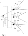
- Fig.1 1 schematically shows a lighting device 1 according to the invention with some basic components.
- the lighting device 1 comprises a light source arrangement 3 with several semiconductor-based light sources in the form of light-emitting diodes 31, 32, 33.
- a control circuit 7 is provided to which the light-emitting diodes 31, 32, 33 are connected, wherein the light-emitting diodes can be controlled individually to emit different light intensities.
- the light sources are preferably arranged rigidly or immovably. However, this does not rule out the possibility of the light sources having an adjustment option, for example for adjustment. Due to the fixed arrangement, the emitted light cones are immovable in relation to the lighting device.
- the lighting device 1 nevertheless enables a movable light field or, more generally, an adjustment of the spatial position of the light field through the mode of operation explained in more detail below.
- An adjusting device 5 is connected to the control circuit 7.
- a simple possibility for such an adjusting device 5 would be, for example, a potentiometer as shown.
- a large number of adjusting devices 5 are possible and the design of the Fig.1 is not limited to a specific control device.
- the control device 5 Depending on its position or the duration or type of actuation, the control device 5 generates a control signal, based on which the currents through the light-emitting diodes 31, 32, 33 and thus their light intensities are individually adjusted by the control circuit.
- the potentiometer is an example of an adjusting device 5 which interacts with the control circuit 7 in such a way that with a successive actuation of the adjusting means the center of gravity of the light field or its center axis progressively moves in one direction. If the rotary knob of the potentiometer is rotated successively in one direction, the light field and thus the center of gravity or the center axis of the light field moves in one direction by varying the light intensities of the LEDs 31, 32, 33; if rotated in the opposite direction, the light field also moves back in the opposite direction.
- a potentiometer is also an example of a sliding or rotary adjusting device (depending on whether it is a sliding or rotary potentiometer), whereby the adjusting device and the control circuit interact in such a way that different sliding or rotary positions of the sliding or rotary adjusting device correspond to different lighting directions.
- the center of gravity is understood to be the center of the light distribution, which is the mean of the spatial positions of the light distribution weighted by the light intensity.
- the center of gravity can therefore also be referred to as the spatial intensity center.
- the center axis of a light cone, or of the light field generated by one or more light cones, runs from the light source through the center of gravity, i.e. the intensity center.
- the light-emitting diodes 31, 32, 33 are further provided with collimation devices which collimate or focus the light of the light-emitting diodes 31, 32, 33 into light cones 41, 42, 43.
- the collimation devices are also referred to below as light bundling devices.
- the light cones 41, 42, 43 are generally directed differently by means of the light bundling devices 13, so that the light-emitting diodes illuminate different areas on an illuminated object.
- the light bundling devices 13 are designed so that adjacent light cones, i.e. those light cones that have the most similar directions overlap. In the representation of the Fig.1 the light cones 41 and 42 and the light cones 42 and 43 are adjacent. Accordingly, the areas of an illuminated object illuminated by the individual LEDs also overlap.
- the light bundling devices 13 can be designed for different positions in such a way that they collimate the light to different degrees, so that a light spot of the same size is achieved at the desired position (direction and distance). In order to keep the additional effort and/or the risk of confusion between different elements during assembly to a minimum, this can be achieved, for example, when using collimating lenses by adjusting the distance to the light-emitting diode.
- the control circuit 7 can now be set in one or more intermediate stages so that the LEDs of adjacent light cones are controlled and operated simultaneously.
- a light field is created whose center of gravity or central axis lies between the centers of gravity or central axes of the light fields or light cones of the individual LEDs 31, 32, 33.
- the center of gravity of the illuminated area can be shifted in the intermediate stages more towards one of the centers of gravity of the areas illuminated by the individual LEDs.
- the term “light cone” in the sense of the invention does not necessarily refer to a cone with a round cross-section. Rather, a light cone is generally understood to be a light field of any shape that widens with increasing distance. Accordingly, the area of an illuminated object illuminated by a light-emitting diode does not have to be round.
- the angle ⁇ between the directions of the centers of gravity or center axes of the light cones of maximum deflection, i.e. between the maximum deflection to the left and the maximum deflection to the right, is 30° to 80°, preferably 35° to 55°. This angle would correspond to the swivel angle in a mechanically pivotable lamp.
- the angle ⁇ can also be related to the number of different directions of the light cones. In the case of the Fig.1 In the example shown, at an angle of 30° to 60°, three light cones of different directions present. This means that each light cone covers 10° to 20° of the entire angle ⁇ .
- the lighting device 1 comprises several light-emitting diodes 31, 32, 33 with one or more light bundling devices 13, which emit light in several light cones 41, 42, 43 in different directions, with an angle in the range of 10° to 20° being included between the directions.
- This embodiment is in particular not limited to the Fig.1 shown number of three LEDs or three light cones.
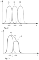
- Fig. 2 shows a schematic diagram of the light intensities of the light cones 41, 42, 43 along a location coordinate x, for example on an illuminated object.
- the focal points 410, 420, 430 of the light cones 41, 42, 43 are offset along the spatial coordinate due to their different directions.
- the adjacent light cones 41, 42, and 42, 43 overlap, so that in general, without being limited to the specific diagram, an area between the adjacent focal points is illuminated by both adjacent light cones.
- the example is also schematic with regard to the overlap of the individual light cones. The overlap is comparatively small. In practical applications, it is usually advisable to provide a larger overlap, although a smaller overlap, such as that shown, can also result in an aesthetically acceptable form of a pivoting light field.
- Fig.3 now shows an intermediate stage in the lighting in the same diagram.
- the two light-emitting diodes 31, 32 are operated together so that their light is emitted in the overlapping light cones 41, 42.
- the light-emitting diodes can now be operated by means of the adjusting device 5 such that the center of gravity of the light field 11 generated by the light-emitting diodes lies between the centers of gravity 410, 420 of the adjacent light cones 41, 42 when an intermediate stage is set.
- an intermediate stage is set in which the light cone 42 has a lower light intensity than the light cone 41.
- the center of gravity 11 of the light field 9 of the lighting device 1 is arranged between the centers of gravity 410, 420 in this setting and is shifted towards the center of gravity of the brighter light cone 410.
- the control circuit 7 is designed such that the respective currents through the light-emitting diodes 31, 32, 33 are selected such that the brightness of the light field 9 remains the same in various intermediate positions or fluctuates by a maximum of 20%, preferably a maximum of 10%.
- the currents through the LEDs and accordingly the light intensities of the light cones 41, 42 are reduced compared to the case where a light cone is generated with only one of the LEDs.
- the currents can also be adjusted such that the center brightness or maximum brightness in the intermediate positions remains the same or fluctuates by a maximum of 20%, preferably by a maximum of 10%.
- the intensities of the light cones 41, 42, 43 are adjusted accordingly, for example by further reducing the current through the LED 32 and further increasing the current through the LED 31 in order to shift the center of gravity of the light field 9 further towards the center of gravity 410 of the light cone 41 generated by the LED 31.
- this adjustment and readjustment can also be carried out gradually instead of abruptly setting the new parameters.
- control circuit 7 can be set up to set an intermediate position or the new parameters with a time delay when the actuating element 5 is actuated and the actuating value is thus changed, by setting the brightness of the LEDs 31, 32, 33, if they are involved, in a sliding manner over time or in several successive intermediate positions.
- the time delay and/or the parameters for controlling the light-emitting diodes via the various adjustable positions can be calculated in a microcontroller and/or stored as values in a memory of the control circuit.
- Fig.1 Three LEDs 31, 32, 33 are provided.
- the example of the Fig.3 but also shows that a displacement of the light field 9, or of its center of gravity 11, according to the invention is easily possible with just two light-emitting diodes.
- a major advantage of the invention is that the alignment of the light field can be carried out without mechanical parts. This not only enables a compact design, but also a robust and easy-to-clean configuration. Protruding mechanical components, which are more difficult to clean and ultimately increase the risk of injury, especially when used in vehicle or aircraft cabins, can be completely dispensed with.
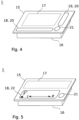
- the lighting device has a front panel behind which the light-emitting diodes are arranged.
- the lighting device can also be designed as a recessed light with a front panel.
- the recessed light comprises a housing 16 with a front panel 15 attached.
- the light-emitting diodes are arranged in the housing 16 and shine through the front panel 15 during operation.
- the control circuit 7 is preferably also accommodated in the housing 16.
- the front panel 15 has an operating element, or if an operating element is integrated into the front panel 15 with which the control device can be operated.
- the operating element comprises a touch element.
- the operating element is designed as a touch operating element.
- a touch-sensitive slider (a so-called “slider") is particularly advantageous for intuitive operation.
- an operating element 18 in the form of a touch-sensitive slider 20 is provided in order to actuate the adjusting device 5 or, more generally, to generate adjusting values for adjusting the beam direction of the lighting device 1.
- the embodiment with a common front panel for several light sources enables a very flat structure precisely due to the mode of operation with fixed light sources and movement of the light field by adjusting intermediate levels. There are clear advantages here, especially as a built-in light in vehicles or passenger cabins.
- a lighting device 1 which comprises a plurality of light sources, in particular a plurality of semiconductor-based light sources in the form of light-emitting diodes, as well as a common front panel for the plurality of light sources, wherein the front panel is at least partially transparent so that the light emitted by the light sources can pass through the front panel to the outside, wherein at least the transparent areas of the front panel are made of glass or plastic.
- This embodiment of the lighting device is also independent of the mode of operation with permanently installed light-emitting diodes and a movement of the light field by setting intermediate brightness levels.
- the light-emitting diodes are again installed in such a way that they emit light in light cones in different directions.
- the light sources can also simply emit light stationary in an immobile light field preset in terms of its spatial position.
- a control element for the user to move the light field does not then have to be provided.
- opaque areas of the front panel can be present due to opaque sections of the carrier material of the front panel or due to opaque coatings.
- the front panel is flat or uniaxially curved in order to ensure a good adaptation to the shape of larger panel parts in which the light is installed.
- control elements can also be used, as shown in the examples of the Fig. 4 and Fig. 5 are provided. As mentioned, touch controls are particularly suitable in order to keep the surface of the front panel flat.
- a touch-sensitive slide control 20 is not restricted to a recessed light with a front panel 15 as the lighting device 1. Rather, such a control element can also be used in other configurations. Accordingly, in one embodiment, a touch-sensitive control element 18, preferably a touch-sensitive slide control, is generally provided for actuating the adjusting device 5. This can be separate from the recessed light, for example in the form of a control element in an armrest and/or in the form of a remote control and/or as a control element in an entertainment system, for example with a touch-sensitive screen.
- an on-off switching element 21 is also provided. This can also be designed as a touch-sensitive operating element if it is integrated into the front panel 15.
- a further control device connected to the control circuit 7 in order to adjust the brightness of the light-emitting diodes 31, 32, 33, or the total light intensity emitted.
- a further control element 19 in the form of a touch-sensitive slider 20 is provided in order to be able to adjust the brightness of the lighting device 1.
- Fig.5 shows a variant of the embodiment according to Fig.4
- This variant is also designed as a recessed light with a front panel 15.
- no separate control elements 18, 19 are provided for brightness and direction.
- a single control element 18 is provided as a two-dimensional control panel in the form of a touch-sensitive matrix controller 22.
- the lighting direction can be adjusted in one direction and the brightness in the direction perpendicular to this can be adjusted by the position of the touch.
- control element is not integrated in the housing, or if an additional control element is provided that is separate from the built-in light. This applies in cases where the light is difficult to reach from the sitting or lying position, for example because there is no installation space available in a favorable position, because a favorable position is not desirable for reasons of design aesthetics, or because an easily accessible position is visually unfavorable. This can also be the case if the person has only limited mobility, e.g. in a hospital bed, but their position can be changed using the bed's electrical adjustment options, so that the lighting direction must also be adapted to the respective situation in order to use the light.
- a mechanically adjustable light would require a motor to change the setting of the light cone in response to a signal from the control device (18, 19).
- a control element can be integrated in an armrest of a seat to be illuminated with the lighting device.
- the control element can comprise a remote control.
- the front panel 15 can be opaque for aesthetic reasons.
- a window 17 can then be provided behind which the LEDs 31, 32, 33 are arranged and which lets the light from the LEDs through.
- the window 17 can in turn be provided with a coating or masking in order to achieve a so-called dead-front effect.
- the interior of the lighting device is illuminated by the Coating or masking conceals the viewer, but the LEDs can shine through the coating or masking.
- a semi-transparent coating that sufficiently darkens the inside of the housing.
- Another example is masking in the form of a structured coating that leaves small areas of the aperture free, for example in a grid pattern, through which the light from the LEDs can escape.
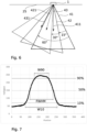
- Fig.6 shows an embodiment for the configuration of the lighting parameters of a lighting device 1 according to the invention.
- the lighting device 1 is designed as a ceiling light that can be installed in a ceiling 25 of the interior of a vehicle or aircraft.
- the light-emitting diodes of the lighting device emit light cones 41, 42, 43, each of which has an opening angle of 60°.
- the directions of adjacent, overlapping light cones in this example each have an angle of 15°.
- the direction of the light cone 43 to the light cone 41 has an angle of 30°.
- the adjacent light cones overlap, but also the next but one light cones, i.e. in the example shown the light cones 41 and 43.
- one embodiment of the invention provides that at least some of the light-emitting diodes 31, 32, 33 are collimated such that the opening angle of the light cones 41, 42, 43 is greater than the angle between the light cones, or between the center axes 411, 421, 431 of the light cones.
- the light-emitting diodes 31, 32, 33 are collimated such that the angle between adjacent light cones is at most equal to half the opening angle of the light cones 41, 42, 43.
- the overlap is expressed in such a way that at least some of the light-emitting diodes 31, 32, 33 are collimated so that at least one of the light cones overlaps both with a second, adjacent light cone and with a third light cone which is adjacent to the second light cone.
- the features described above serve to achieve a smooth transition of the shape of the light fields when moving the light field or when swiveling the resulting light cone in the intermediate positions.
- a so-called top hat profile with a sharp border is therefore rather disadvantageous.
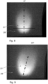
- Fig.7 shows a brightness gradient on an illuminated surface along a line, as generated by one of the collimated light-emitting diodes.
- a photographic image of the associated light spot 27 on a surface 28 illuminated by the lighting device 1 shows Fig.8 .
- the line along which the brightness gradient was extracted from the gray values of the image is shown in Fig.8 as a horizontal bar, which runs through the brightness maximum of the light spot 27.
- Three lines are drawn which mark the levels of 10%, 50% and 90% of the maximum brightness. The width of the brightness distribution at the 50% line is therefore the half-width of the distribution.
- a distribution which is favourable to support an optical impression of a light spot which can be continuously adjusted in its position can be achieved if the flanks do not rise too abruptly, as explained above.
- the values W90, W10 and FWHM are in Fig.7 Without being limited to the examples shown, it is preferred if the above-mentioned parameter has a value of at least 0.5. On the other hand, it is also advantageous not to let the distribution become too flat. In this case, the light field would become too wide, which is undesirable in a reading light, for example, since the brightness is to be concentrated on the object to be illuminated. The pivoting of the light field is then also less clearly perceptible. According to another embodiment, it is therefore provided that the above-mentioned parameter (W10-W90) / FWHM has a value of less than 1.6.
- the brightness distribution of the light of one of the light-emitting diodes preferably all light-emitting diodes 31, 32, 33 on a surface 28 illuminated by the lighting device 1 along a line through the brightness maximum of the light distribution of the parameters (W10-W90) / FWHM has a value in the range of 0.5 to 1.6.
- the Fig. 9 to 11 show further photographic images of the area illuminated by a lighting device, or light spot 27 on a surface 28.
- the Fig. 8 to 10 show light spots 27, which are formed by light cones of individual light-emitting diodes 31, 32, 33, but according to the Fig.6 shown configuration were created at different angles.
- the angle is 0°
- the light cone has to the light cone to Fig.8 an angle of 15°
- in the example of Fig.10 an angle of 30°.
- the light spot is created by superimposing adjacent light cones of two light-emitting diodes, or by superimposing the light spots from Fig.9 and Fig.10
- the light intensity of both LEDs is halved, so that the total brightness of the light field corresponds to that of the light cones of the individual LEDs.
- This superposition results in an effective angle of the central axis, or the direction of the center of gravity, to the direction of the center of gravity of the light spot from Fig.8 of 22.5°.
- the extension of the light spot at the intermediate position is Fig. 11 not noticeably enlarged.
- Fig. 12 shows various possibilities for the construction of a lighting device 1, with which a collimation of the light from the LEDs into light cones in different directions is possible.
- the LEDs 31, 32, 33 are mounted on pedestals 35, as shown in example (a), which have partially inclined holding surfaces, so that the LEDs 31, 32, 33 together with the light bundling devices 13 are tilted at the intended angle with respect to the surface of the circuit board.
- the LEDs can be attached to inclined mounting elements on a base, in particular a circuit board.
- Lenses are provided here as collimating elements 13, for example.
- suitable collimating elements or light bundling devices 13 can also be provided, which capture unwanted light emitted from the side.
- open tubes can cover the LEDs at the sides for this purpose.
- a base 37 with a curved surface is provided. If the light-emitting diodes 31, 32, 33 are connected to the light bundling devices 13 with this base, they assume a certain angle according to the local inclination of the surface. inclination.
- a flexible circuit board 29 can also be provided for this purpose, on which the light-emitting diodes are mounted.
- optical deflection elements 38 can generally be provided in order to generate light cones in different directions.
- This embodiment offers the advantage that the light-emitting diodes can be mounted directly on a flat circuit board 29.
- the function of the light bundling devices 13 and the deflection elements 38 can also be combined in an optical element (not shown). This is then designed, for example, as an optical free-form element.
- the optical elements can also be particularly advantageously integrated into the housing cover or the front panel.
- the front panel can have sections shaped as lenses.
- optical elements can also be located as elements of a component on a common base plate.
- this would be a lens array and in example 12 (c) an array of free-form elements. This can simplify the manufacture of the optical elements and also the assembly in the luminaire.
- Fig. 13 shows a swivel line 45 of an area illuminated by a conventional lighting device when a surface is illuminated at an angle.
- the light field 9 moves along this swivel line 45 when the light source is mechanically swiveled between an angle of -30° and an angle of +30° and the surface to be illuminated is illuminated at an angle. Since the swivel axis is at an angle to the surface, the line is not straight.
- the swivel line represents the edge of a conic section and is typically a hyperbola.
- a pivot line 45 of basically any shape can now be set by suitable alignment of the individual light sources and light bundling devices 13, even when an area to be illuminated is illuminated at an angle.
- Fig. 14 an area to be illuminated is illuminated at an angle by the lighting device 1.
- the individual light cones of the LEDs are aligned in such a way that these support points lie on a straight line. Accordingly, the intermediate positions created by superimposing the light cones also lie on the straight pivot line 45. Differently shaped paths or pivot lines 45 can also be created by appropriately aligning the light cones of the LEDs.
- FIG. 15 shows another example in which part of the swivel line 45 is deviated from a straight path Such a path could be desirable, for example, if part of the surface to be illuminated is curved, so that the non-linear path of the swivel line compensates for the curvature and the impression of a straight-line swivel is created.
- the embodiments of the Fig. 14 and Fig. 15 What is common, without limitation to the specific embodiments shown, is that the beam directions of the light cones of the at least three light-emitting diodes do not all lie in one plane.
- the light spot positions generated by the lighting device can therefore be arranged along a - not necessarily straight - one-dimensional line.
- they can also cover a two-dimensional field, so that the positions can be adjusted not only in one but in two dimensions.
- any light spot position can be achieved not by blending just two light cones, but by several light cones, in particular three light cones in a triangular arrangement or four light cones in a square or rectangular arrangement.
- Fig. 16 shows an exemplary embodiment.
- the directions of the light cones of the LEDs, or the light spots generated by the light cones, are distributed in two spatial directions, so that the light field can be swiveled within a two-dimensional swivel range 46 by superimposing the light cones and setting intermediate positions.
- the swivel range 46 is a rectangular area in the example shown, but can also have any other shape.
- the invention provides that the light cones of the light-emitting diodes 31, 32, 33 are aligned such that the areas illuminated by the light cones are distributed in two spatial directions, so that by superimposing the light cones and thus by setting intermediate positions, the light field 9, or the area illuminated by the lighting device 1, can be moved, preferably pivoted, within a two-dimensional pivoting range 46.
- the lighting device 1 can be used in particular as a reading light for adjustable seating or reclining furniture, in which the position of the area to be illuminated changes with the sitting or reclining position. Typical applications for this are reading lights in airplanes, ships, trains, automobiles or other vehicles. In addition, this light is also particularly suitable for adjustable beds, in particular for hospital beds in hospitals or similar facilities.
- Lighting device 3 Light source arrangement 5 Adjustment device 7 Control circuit 9 Light field 11 Focus of 9 13 Light bundling device 15 Front panel 16 Housing 17 Window 18, 19 Control element 20 touch-sensitive slider 21 On-off switching element 22 touch-sensitive matrix controller 25 Ceiling 27 Light spot 28 illuminated area 29 Circuit board 31, 32, 33 LED 35 Podium 37 Base with curved surface 38 optical deflection element 41, 42, 43 Light cone 45 Swing line 46 two-dimensional swivel range 50 Sliding adjustment device 51 Rotary adjustment device 410, 420, 430 Focus of the light cones 411, 421, 431 Center axes of the light cones
Landscapes
- Engineering & Computer Science (AREA)
- General Engineering & Computer Science (AREA)
- Mechanical Engineering (AREA)
- Theoretical Computer Science (AREA)
- Human Computer Interaction (AREA)
- Physics & Mathematics (AREA)
- General Physics & Mathematics (AREA)
- Microelectronics & Electronic Packaging (AREA)
- Arrangements Of Lighting Devices For Vehicle Interiors, Mounting And Supporting Thereof, Circuits Therefore (AREA)
- Non-Portable Lighting Devices Or Systems Thereof (AREA)
- Fastening Of Light Sources Or Lamp Holders (AREA)
Claims (16)
- Dispositif d'éclairage (1) comprenant un agencement de source lumineuse (3) avec plusieurs sources lumineuses à base de semiconducteurs, sous forme de diodes électroluminescentes (31, 32, 33), dont la lumière émise est concentrée de manière à ce qu'elle forme des cônes de lumière (41, 42, 43) à orientations différentes, qui se chevauchent dans un champ lumineux, le dispositif d'éclairage (1) présentant un dispositif de réglage (5), destiné à émettre un signal de réglage pour l'ajustement de la direction d'éclairage, et un circuit d'activation (7) qui est relié au dispositif de réglage (5), le dispositif de réglage (5) permettant d'ajuster des niveaux intermédiaires dans lesquels des diodes électroluminescentes (31, 32, 33) de cônes de lumière (41, 42, 43) adjacents et se chevauchant peuvent être activées ensemble et avec une intensité lumineuse variable par le circuit d'activation (7), de manière à ce que la zone principale du champ lumineux (9) généré par les diodes électroluminescentes se situe pour les niveaux intermédiaires entre les zones principales (410, 420, 430) de cônes de lumière (41, 42, 43) adjacents,
sachant que les diodes électroluminescentes (31, 32, 33) peuvent être activées individuellement pour émettre des intensités lumineuses différentes, et qu'au moins une partie des diodes électroluminescentes (31, 32, 33) est soumise à une collimation telle qu'au moins un des cônes de lumière se chevauche aussi bien avec un deuxième cône de lumière adjacent qu'avec un troisième cône de lumière qui est adjacent au deuxième cône de lumière, la luminosité du champ lumineux restant la même dans les différents niveaux intermédiaires ou variant au maximum de 20 %, ce qui a pour effet que les sources lumineuses émettent de la lumière respectivement dans un cône de lumière immobile, l'angle α entre les directions des zones principales des cônes de lumière à déviation maximale étant de 30° à 80°, de préférence de 35° à 55°, le dispositif d'éclairage (1) étant réalisé comme luminaire encastrable doté d'un panneau frontal (15), les diodes électroluminescentes (31, 32, 33) étant disposées derrière le panneau frontal (15), et le panneau frontal étant transparent au moins en partie. - Dispositif d'éclairage (1) selon la revendication précédente, caractérisé en ce que les sources lumineuses sont installées de manière fixe.
- Dispositif d'éclairage (1) selon une des revendications précédentes, caractérisé en ce qu'il présente au moins une des caractéristiques suivantes :- le circuit d'activation (7) est conçu pour activer les diodes électroluminescentes (31, 32, 33) de manière à ce que la luminosité du champ lumineux (9) reste la même dans les niveaux intermédiaires ou varie au maximum de 10 %,- le réglage des diodes électroluminescentes (31, 32, 33) s'effectue de manière à ce que la luminosité au centre ou luminosité maximale reste la même dans les niveaux intermédiaires ou varie au maximum de 20 %, de préférence au maximum de 10 %.
- Dispositif d'éclairage selon la revendication précédente, caractérisé en ce que le dispositif de réglage (5) et le circuit d'activation (7) coopèrent de manière à ce que suite à un actionnement successif du moyen de réglage, la zone principale (11) du champ lumineux (10) se déplace.
- Dispositif d'éclairage selon une des revendications précédentes, caractérisé en ce que le dispositif de réglage (5) comprend un dispositif d'ajustement coulissant ou tournant (50, 51), le dispositif de réglage (5) et le circuit d'activation (7) coopérant de manière à ce que des positions de coulissement ou de rotation différentes du dispositif d'ajustement coulissant ou tournant (50, 51) correspondent à des dispositifs d'éclairage différents.
- Dispositif d'éclairage (1) selon une des revendications précédentes, caractérisé en ce qu'un élément de commande (18) est intégré dans le panneau frontal (15) et permet d'actionner l'élément de réglage (5).
- Dispositif d'éclairage selon une des revendications précédentes, caractérisé par un élément de commande (18) tactile, de préférence un régulateur à curseur tactile, destiné à actionner l'élément de réglage (5).
- Dispositif d'éclairage selon une des revendications précédentes, caractérisé par un dispositif de réglage supplémentaire relié au circuit d'activation (7) et destiné à régler l'intensité lumineuse totale émise par le dispositif d'éclairage (1).
- Dispositif d'éclairage selon une des revendications précédentes, caractérisé en ce que le circuit d'activation (7) est conçu pour effectuer, en réaction à la variation d'une valeur réglante de l'élément de réglage (5), un ajustement d'une position intermédiaire, avec un temps de retard, de manière à ce que les luminosités des diodes électroluminescentes (31, 32, 33) soient ajustées avec un glissement dans le temps ou avec plusieurs positions intermédiaires successives.
- Dispositif d'éclairage selon une des revendications précédentes, caractérisé en ce que la pluralité de diodes électroluminescentes (31, 32, 33) émet de la lumière dans plusieurs cônes de lumière (41, 42, 43) ayant des directions différentes, sachant qu'un angle compris dans la plage allant de 10° à 20° est formé entre les directions.
- Dispositif d'éclairage selon une des revendications précédentes, caractérisé en ce qu'il présente au moins une des caractéristiques suivantes :- au moins une partie des diodes électroluminescentes (31, 32, 33) fait l'objet d'une collimation telle que l'angle d'ouverture des cônes de lumière (41, 42, 43) soit plus grand que l'angle entre les cônes de lumière (41, 42, 43),- au moins une partie des diodes électroluminescentes (31, 32, 33) fait l'objet d'une collimation telle que l'angle entre des cônes de lumière (41, 42, 43) adjacents soit au maximum égal à la moitié de l'angle d'ouverture des cônes de lumière (41, 42, 43).
- Dispositif d'éclairage selon une des revendications précédentes, caractérisé en ce que pour la distribution de luminosité de la lumière de l'une des diodes électroluminescentes (31, 32, 33), de préférence de l'ensemble des diodes électroluminescentes (31, 32, 33), sur une surface (28) éclairée par le dispositif d'éclairage (1), le long d'une ligne passant par le maximum de luminosité de la répartition de lumière, le paramètre (W10-W90)/FWHM présente une valeur comprise dans la plage allant de 0,5 à 1,6, où W10 désigne la largeur de la distribution de luminosité pour 10 % de la luminosité maximale, W90 désigne la largeur de la distribution de luminosité pour 90 % de la luminosité maximale et FWHM désigne la largeur à mi-hauteur de la distribution de luminosité.
- Dispositif d'éclairage selon une des revendications précédentes, caractérisé en ce qu'il présente au moins une des caractéristiques suivantes :- les diodes électroluminescentes (31, 32, 33) sont fixées à des éléments de montage inclinés, sur un support, notamment une carte de circuit imprimé (29),- les diodes électroluminescentes (31, 32, 33) sont reliées à un support (37) à surface bombée,- il est prévu des éléments de déviation optiques (38) pour générer des cônes de lumière (41, 42, 43) ayant des directions différentes.
- Dispositif d'éclairage selon une des revendications précédentes, comprenant au moins trois diodes électroluminescentes (31, 32, 33), caractérisé en ce que les directions de rayonnement des cônes de lumière produits par les diodes électroluminescentes ne se situent pas toutes dans le même plan.
- Dispositif d'éclairage selon une des revendications précédentes, comprenant au moins trois diodes électroluminescentes (31, 32, 33), les cônes de lumière des diodes électroluminescentes (31, 32, 33) étant orientés de manière à ce que les zones éclairées par les cônes de lumière soient réparties dans deux directions dans l'espace, de sorte que le champ lumineux (9) peut être déplacé à l'intérieur d'une zone de pivotement (46) bidimensionnelle, par chevauchement des cônes de lumière et réglage de positions intermédiaires.
- Utilisation d'un dispositif d'éclairage (1) selon une des revendications précédentes, en tant que lampe de lecture- pour des meubles d'assise ou de couchage réglables, en particulier des lits de malade,- dans des avions, des navires, des trains, des automobiles ou d'autres véhicules.
Applications Claiming Priority (1)
| Application Number | Priority Date | Filing Date | Title |
|---|---|---|---|
| DE102018108278.9A DE102018108278A1 (de) | 2018-04-09 | 2018-04-09 | Halbleiterbasierte Beleuchtungsvorrichtung |
Publications (2)
| Publication Number | Publication Date |
|---|---|
| EP3553374A1 EP3553374A1 (fr) | 2019-10-16 |
| EP3553374B1 true EP3553374B1 (fr) | 2024-08-28 |
Family
ID=66217695
Family Applications (1)
| Application Number | Title | Priority Date | Filing Date |
|---|---|---|---|
| EP19166963.9A Active EP3553374B1 (fr) | 2018-04-09 | 2019-04-03 | Dispositif d'éclairage à base de semi-conducteur |
Country Status (3)
| Country | Link |
|---|---|
| US (1) | US10813185B2 (fr) |
| EP (1) | EP3553374B1 (fr) |
| DE (1) | DE102018108278A1 (fr) |
Families Citing this family (8)
| Publication number | Priority date | Publication date | Assignee | Title |
|---|---|---|---|---|
| US20220034497A1 (en) * | 2020-02-18 | 2022-02-03 | Exposure Illumination Architects, Inc. | Light emitting heat dissipating structure |
| US11898725B2 (en) * | 2020-07-01 | 2024-02-13 | Self Electronics Co., Ltd. | Jewelry lighting lamp and a jewelry lighting method |
| DE102021104700B4 (de) * | 2021-02-26 | 2026-04-02 | Schott Ag | Beleuchtungseinrichtung und optisches Element für eine Beleuchtungseinrichtung |
| DE202021102154U1 (de) * | 2021-04-22 | 2022-07-25 | Ledlenser GmbH & Co. KG | Leuchte |
| EP4242060B1 (fr) * | 2022-03-08 | 2025-04-23 | Goodrich Lighting Systems GmbH & Co. KG | Lampe de lecture de passager d'aéronef |
| DE102023125725A1 (de) | 2023-09-22 | 2025-03-27 | Schott Ag | Laser-strukturiertes optisches Element |
| DE102024205935B3 (de) * | 2024-06-26 | 2025-07-10 | Volkswagen Aktiengesellschaft | Fahrzeug und Beleuchtungssystem mit direkter Helligkeitswahl |
| WO2026077789A1 (fr) * | 2024-10-08 | 2026-04-16 | Signify Holding B.V. | Système de génération de lumière pour un éclairage général et un éclairage de fenêtre ou de paroi séparée |
Citations (4)
| Publication number | Priority date | Publication date | Assignee | Title |
|---|---|---|---|---|
| GB2473311A (en) * | 2010-05-21 | 2011-03-09 | Oliver Shakespeare | Lighting device with separately addressable, concentric sets of LEDs |
| JP2011222182A (ja) * | 2010-04-06 | 2011-11-04 | Minebea Co Ltd | 照明装置 |
| US20130250590A1 (en) * | 2007-11-16 | 2013-09-26 | Koninklijke Philips Electronics N.V. | Direction controllable lighting unit with ultrasound |
| US20160123564A1 (en) * | 2014-11-03 | 2016-05-05 | Osram Sylvania Inc. | Solid-state luminaire with electronically adjustable light beam distribution |
Family Cites Families (15)
| Publication number | Priority date | Publication date | Assignee | Title |
|---|---|---|---|---|
| DE10034594B4 (de) * | 2000-07-14 | 2006-03-16 | Sirona Dental Systems Gmbh | Zahnärztliche Behandlungsleuchte |
| US6796690B2 (en) * | 2002-03-14 | 2004-09-28 | The Boeing Company | LED light source |
| DE10251133B3 (de) * | 2002-10-31 | 2004-07-29 | Gerd Reime | Einrichtung zur Steuerung einer Beleuchtung, insbesondere für Fahrzeuginnenräume sowie Verfahren zu ihrer Steuerung |
| US7253744B2 (en) * | 2005-05-23 | 2007-08-07 | The Boeing Company | Automatically adjusting passenger reading light system and method |
| US20080315798A1 (en) * | 2005-12-23 | 2008-12-25 | Koninklijke Philips Electronics N.V. | User Interface For Lighting Systems |
| US7413327B2 (en) * | 2006-04-10 | 2008-08-19 | The Boeing Company | Vehicle lighting fixture |
| DE102006048711B4 (de) | 2006-10-14 | 2009-05-07 | Dae Systems Gmbh | Einbauleuchte |
| US9100124B2 (en) * | 2007-05-24 | 2015-08-04 | Federal Law Enforcement Development Services, Inc. | LED Light Fixture |
| DE102008055812B4 (de) | 2008-11-04 | 2011-02-17 | Airbus Operations Gmbh | Überkopf-Leseleuchtensystem für einen Passagiersitz |
| DE102010042287B9 (de) | 2010-10-11 | 2013-07-11 | Schott Ag | Beleuchtungsvorrichtung, insbesondere Leseleuchte |
| KR101265650B1 (ko) * | 2011-12-01 | 2013-05-22 | 엘지전자 주식회사 | 조명 장치 및 리모컨을 이용한 조명 제어 방법 |
| US9587805B2 (en) * | 2013-09-20 | 2017-03-07 | Osram Sylvania Inc. | Solid-state luminaire with electronically adjustable light beam distribution |
| EP3114902A1 (fr) * | 2014-02-28 | 2017-01-11 | Bombardier Inc. | Procédé, système et produit de programme exécutable de commande de services pour passager |
| DE102015203890A1 (de) * | 2015-03-04 | 2016-09-08 | Hella Kgaa Hueck & Co. | Verfahren zum Betreiben einer Beleuchtungsvorrichtung |
| US10272833B2 (en) * | 2016-12-19 | 2019-04-30 | Magna Mirrors Of America, Inc. | Vehicle glass roof with light controls and interior lights |
-
2018
- 2018-04-09 DE DE102018108278.9A patent/DE102018108278A1/de not_active Withdrawn
-
2019
- 2019-04-03 EP EP19166963.9A patent/EP3553374B1/fr active Active
- 2019-04-09 US US16/379,670 patent/US10813185B2/en active Active
Patent Citations (4)
| Publication number | Priority date | Publication date | Assignee | Title |
|---|---|---|---|---|
| US20130250590A1 (en) * | 2007-11-16 | 2013-09-26 | Koninklijke Philips Electronics N.V. | Direction controllable lighting unit with ultrasound |
| JP2011222182A (ja) * | 2010-04-06 | 2011-11-04 | Minebea Co Ltd | 照明装置 |
| GB2473311A (en) * | 2010-05-21 | 2011-03-09 | Oliver Shakespeare | Lighting device with separately addressable, concentric sets of LEDs |
| US20160123564A1 (en) * | 2014-11-03 | 2016-05-05 | Osram Sylvania Inc. | Solid-state luminaire with electronically adjustable light beam distribution |
Also Published As
| Publication number | Publication date |
|---|---|
| EP3553374A1 (fr) | 2019-10-16 |
| DE102018108278A1 (de) | 2019-10-10 |
| US20190313497A1 (en) | 2019-10-10 |
| US10813185B2 (en) | 2020-10-20 |
Similar Documents
| Publication | Publication Date | Title |
|---|---|---|
| EP3553374B1 (fr) | Dispositif d'éclairage à base de semi-conducteur | |
| DE102011005967B4 (de) | Beleuchtungssystem für ein Kraftfahrzeug | |
| EP1832452B1 (fr) | Dispositif d'écoulement d'air avec rétrosignal visuel | |
| EP2349781B1 (fr) | Plafonnier de lecture pour un siège de passager | |
| EP2239494B1 (fr) | Agencement destiné à l'éclairage ambiant | |
| EP3678878B1 (fr) | Véhicule à moteur avec un dispositif de sortie d'air pour un intérieur du véhicule à moteur | |
| EP3907107B1 (fr) | Système de projection pour un véhicule et véhicule pourvu de système de projection | |
| EP2495487A1 (fr) | Lumière d'opération et procédé d'illumination d'un point d'opération | |
| EP3765320A1 (fr) | Dispositif de ventilation pour une zone intérieure d'un véhicule automobile | |
| WO2021180492A1 (fr) | Dispositif d'éclairage d'environnement pour un véhicule automobile | |
| DE102008064283B3 (de) | Optische Sollwertanzeigevorrichtung für eine Fahrzeugkomponente | |
| DE102014202753A1 (de) | Flugzeugkabinenanordnung | |
| EP1834876A2 (fr) | Siège avec une unité d'éclairage de travail | |
| WO2013050175A1 (fr) | Hotte de laboratoire et en particulier poste de sécurité microbiologique comprenant un éclairage à diodes électroluminescentes | |
| WO2008061767A1 (fr) | Lampe d'examen médical ou d'intervention chirurgicale | |
| DE202015102061U1 (de) | Innenbeleuchtung eines Fahrzeugs | |
| DE202010015526U1 (de) | Leuchte, insbesondere Leuchte für einen Fahrzeugsitz, insbesondere für einen Fluggastsitz | |
| EP3081855B1 (fr) | Projecteur | |
| EP3836758B1 (fr) | Procédé de commande d'un système d'éclairage d'un salle sanitaire et système d'éclairage d'un salle sanitaire | |
| DE102009051026A1 (de) | LED-Beleuchtungsvorrichtung umfassend wenigstens eine LED und eine Platine, auf der die LED angeordnet ist, und Kraftfahrzeug | |
| DE102004054696B4 (de) | Lüftungsdüse für einen Lüftungsschacht in einem Kraftfahrzeug | |
| EP3446901B1 (fr) | Dispositif d'évacuation d'air permettant l'évacuation d'air dans un espace intérieur d'un véhicule | |
| DE10354236B4 (de) | Vorrichtung zur Illumination von Fahrgastsitzbereichen eines Verkehrsmittels und Verkehrsmittel | |
| WO2004015731A1 (fr) | Piece pouvant etre eclairee | |
| DE202006004307U1 (de) | Sitzvorrichtung |
Legal Events
| Date | Code | Title | Description |
|---|---|---|---|
| STAA | Information on the status of an ep patent application or granted ep patent |
Free format text: STATUS: EXAMINATION IS IN PROGRESS |
|
| PUAI | Public reference made under article 153(3) epc to a published international application that has entered the european phase |
Free format text: ORIGINAL CODE: 0009012 |
|
| 17P | Request for examination filed |
Effective date: 20190403 |
|
| AK | Designated contracting states |
Kind code of ref document: A1 Designated state(s): AL AT BE BG CH CY CZ DE DK EE ES FI FR GB GR HR HU IE IS IT LI LT LU LV MC MK MT NL NO PL PT RO RS SE SI SK SM TR |
|
| AX | Request for extension of the european patent |
Extension state: BA ME |
|
| RBV | Designated contracting states (corrected) |
Designated state(s): AL AT BE BG CH CY CZ DE DK EE ES FI FR GB GR HR HU IE IS IT LI LT LU LV MC MK MT NL NO PL PT RO RS SE SI SK SM TR |
|
| P01 | Opt-out of the competence of the unified patent court (upc) registered |
Effective date: 20230516 |
|
| REG | Reference to a national code |
Ref country code: DE Free format text: PREVIOUS MAIN CLASS: F21V0014020000 Ipc: F21V0023040000 Ref country code: DE Ref legal event code: R079 Ref document number: 502019011966 Country of ref document: DE Free format text: PREVIOUS MAIN CLASS: F21V0014020000 Ipc: F21V0023040000 |
|
| GRAP | Despatch of communication of intention to grant a patent |
Free format text: ORIGINAL CODE: EPIDOSNIGR1 |
|
| STAA | Information on the status of an ep patent application or granted ep patent |
Free format text: STATUS: GRANT OF PATENT IS INTENDED |
|
| INTG | Intention to grant announced |
Effective date: 20240424 |
|
| RIC1 | Information provided on ipc code assigned before grant |
Ipc: F21V 23/04 20060101AFI20240412BHEP |
|
| GRAS | Grant fee paid |
Free format text: ORIGINAL CODE: EPIDOSNIGR3 |
|
| GRAA | (expected) grant |
Free format text: ORIGINAL CODE: 0009210 |
|
| STAA | Information on the status of an ep patent application or granted ep patent |
Free format text: STATUS: THE PATENT HAS BEEN GRANTED |
|
| AK | Designated contracting states |
Kind code of ref document: B1 Designated state(s): AL AT BE BG CH CY CZ DE DK EE ES FI FR GB GR HR HU IE IS IT LI LT LU LV MC MK MT NL NO PL PT RO RS SE SI SK SM TR |
|
| REG | Reference to a national code |
Ref country code: GB Ref legal event code: FG4D Free format text: NOT ENGLISH |
|
| REG | Reference to a national code |
Ref country code: CH Ref legal event code: EP |
|
| REG | Reference to a national code |
Ref country code: DE Ref legal event code: R096 Ref document number: 502019011966 Country of ref document: DE |
|
| REG | Reference to a national code |
Ref country code: IE Ref legal event code: FG4D Free format text: LANGUAGE OF EP DOCUMENT: GERMAN |
|
| REG | Reference to a national code |
Ref country code: LT Ref legal event code: MG9D |
|
| PG25 | Lapsed in a contracting state [announced via postgrant information from national office to epo] |
Ref country code: NO Free format text: LAPSE BECAUSE OF FAILURE TO SUBMIT A TRANSLATION OF THE DESCRIPTION OR TO PAY THE FEE WITHIN THE PRESCRIBED TIME-LIMIT Effective date: 20241128 |
|
| PG25 | Lapsed in a contracting state [announced via postgrant information from national office to epo] |
Ref country code: PT Free format text: LAPSE BECAUSE OF FAILURE TO SUBMIT A TRANSLATION OF THE DESCRIPTION OR TO PAY THE FEE WITHIN THE PRESCRIBED TIME-LIMIT Effective date: 20241230 Ref country code: NL Free format text: LAPSE BECAUSE OF FAILURE TO SUBMIT A TRANSLATION OF THE DESCRIPTION OR TO PAY THE FEE WITHIN THE PRESCRIBED TIME-LIMIT Effective date: 20240828 Ref country code: GR Free format text: LAPSE BECAUSE OF FAILURE TO SUBMIT A TRANSLATION OF THE DESCRIPTION OR TO PAY THE FEE WITHIN THE PRESCRIBED TIME-LIMIT Effective date: 20241129 Ref country code: FI Free format text: LAPSE BECAUSE OF FAILURE TO SUBMIT A TRANSLATION OF THE DESCRIPTION OR TO PAY THE FEE WITHIN THE PRESCRIBED TIME-LIMIT Effective date: 20240828 Ref country code: PL Free format text: LAPSE BECAUSE OF FAILURE TO SUBMIT A TRANSLATION OF THE DESCRIPTION OR TO PAY THE FEE WITHIN THE PRESCRIBED TIME-LIMIT Effective date: 20240828 |
|
| PG25 | Lapsed in a contracting state [announced via postgrant information from national office to epo] |
Ref country code: BG Free format text: LAPSE BECAUSE OF FAILURE TO SUBMIT A TRANSLATION OF THE DESCRIPTION OR TO PAY THE FEE WITHIN THE PRESCRIBED TIME-LIMIT Effective date: 20240828 |
|
| PG25 | Lapsed in a contracting state [announced via postgrant information from national office to epo] |
Ref country code: LV Free format text: LAPSE BECAUSE OF FAILURE TO SUBMIT A TRANSLATION OF THE DESCRIPTION OR TO PAY THE FEE WITHIN THE PRESCRIBED TIME-LIMIT Effective date: 20240828 |
|
| REG | Reference to a national code |
Ref country code: NL Ref legal event code: MP Effective date: 20240828 |
|
| PG25 | Lapsed in a contracting state [announced via postgrant information from national office to epo] |
Ref country code: IS Free format text: LAPSE BECAUSE OF FAILURE TO SUBMIT A TRANSLATION OF THE DESCRIPTION OR TO PAY THE FEE WITHIN THE PRESCRIBED TIME-LIMIT Effective date: 20241228 |
|
| PG25 | Lapsed in a contracting state [announced via postgrant information from national office to epo] |
Ref country code: HR Free format text: LAPSE BECAUSE OF FAILURE TO SUBMIT A TRANSLATION OF THE DESCRIPTION OR TO PAY THE FEE WITHIN THE PRESCRIBED TIME-LIMIT Effective date: 20240828 |
|
| PG25 | Lapsed in a contracting state [announced via postgrant information from national office to epo] |
Ref country code: RS Free format text: LAPSE BECAUSE OF FAILURE TO SUBMIT A TRANSLATION OF THE DESCRIPTION OR TO PAY THE FEE WITHIN THE PRESCRIBED TIME-LIMIT Effective date: 20241128 Ref country code: ES Free format text: LAPSE BECAUSE OF FAILURE TO SUBMIT A TRANSLATION OF THE DESCRIPTION OR TO PAY THE FEE WITHIN THE PRESCRIBED TIME-LIMIT Effective date: 20240828 |
|
| PG25 | Lapsed in a contracting state [announced via postgrant information from national office to epo] |
Ref country code: RS Free format text: LAPSE BECAUSE OF FAILURE TO SUBMIT A TRANSLATION OF THE DESCRIPTION OR TO PAY THE FEE WITHIN THE PRESCRIBED TIME-LIMIT Effective date: 20241128 Ref country code: PT Free format text: LAPSE BECAUSE OF FAILURE TO SUBMIT A TRANSLATION OF THE DESCRIPTION OR TO PAY THE FEE WITHIN THE PRESCRIBED TIME-LIMIT Effective date: 20241230 Ref country code: PL Free format text: LAPSE BECAUSE OF FAILURE TO SUBMIT A TRANSLATION OF THE DESCRIPTION OR TO PAY THE FEE WITHIN THE PRESCRIBED TIME-LIMIT Effective date: 20240828 Ref country code: NO Free format text: LAPSE BECAUSE OF FAILURE TO SUBMIT A TRANSLATION OF THE DESCRIPTION OR TO PAY THE FEE WITHIN THE PRESCRIBED TIME-LIMIT Effective date: 20241128 Ref country code: NL Free format text: LAPSE BECAUSE OF FAILURE TO SUBMIT A TRANSLATION OF THE DESCRIPTION OR TO PAY THE FEE WITHIN THE PRESCRIBED TIME-LIMIT Effective date: 20240828 Ref country code: LV Free format text: LAPSE BECAUSE OF FAILURE TO SUBMIT A TRANSLATION OF THE DESCRIPTION OR TO PAY THE FEE WITHIN THE PRESCRIBED TIME-LIMIT Effective date: 20240828 Ref country code: IS Free format text: LAPSE BECAUSE OF FAILURE TO SUBMIT A TRANSLATION OF THE DESCRIPTION OR TO PAY THE FEE WITHIN THE PRESCRIBED TIME-LIMIT Effective date: 20241228 Ref country code: HR Free format text: LAPSE BECAUSE OF FAILURE TO SUBMIT A TRANSLATION OF THE DESCRIPTION OR TO PAY THE FEE WITHIN THE PRESCRIBED TIME-LIMIT Effective date: 20240828 Ref country code: GR Free format text: LAPSE BECAUSE OF FAILURE TO SUBMIT A TRANSLATION OF THE DESCRIPTION OR TO PAY THE FEE WITHIN THE PRESCRIBED TIME-LIMIT Effective date: 20241129 Ref country code: FI Free format text: LAPSE BECAUSE OF FAILURE TO SUBMIT A TRANSLATION OF THE DESCRIPTION OR TO PAY THE FEE WITHIN THE PRESCRIBED TIME-LIMIT Effective date: 20240828 Ref country code: ES Free format text: LAPSE BECAUSE OF FAILURE TO SUBMIT A TRANSLATION OF THE DESCRIPTION OR TO PAY THE FEE WITHIN THE PRESCRIBED TIME-LIMIT Effective date: 20240828 Ref country code: BG Free format text: LAPSE BECAUSE OF FAILURE TO SUBMIT A TRANSLATION OF THE DESCRIPTION OR TO PAY THE FEE WITHIN THE PRESCRIBED TIME-LIMIT Effective date: 20240828 |
|
| PG25 | Lapsed in a contracting state [announced via postgrant information from national office to epo] |
Ref country code: SM Free format text: LAPSE BECAUSE OF FAILURE TO SUBMIT A TRANSLATION OF THE DESCRIPTION OR TO PAY THE FEE WITHIN THE PRESCRIBED TIME-LIMIT Effective date: 20240828 Ref country code: RO Free format text: LAPSE BECAUSE OF FAILURE TO SUBMIT A TRANSLATION OF THE DESCRIPTION OR TO PAY THE FEE WITHIN THE PRESCRIBED TIME-LIMIT Effective date: 20240828 Ref country code: DK Free format text: LAPSE BECAUSE OF FAILURE TO SUBMIT A TRANSLATION OF THE DESCRIPTION OR TO PAY THE FEE WITHIN THE PRESCRIBED TIME-LIMIT Effective date: 20240828 |
|
| PG25 | Lapsed in a contracting state [announced via postgrant information from national office to epo] |
Ref country code: EE Free format text: LAPSE BECAUSE OF FAILURE TO SUBMIT A TRANSLATION OF THE DESCRIPTION OR TO PAY THE FEE WITHIN THE PRESCRIBED TIME-LIMIT Effective date: 20240828 |
|
| PG25 | Lapsed in a contracting state [announced via postgrant information from national office to epo] |
Ref country code: CZ Free format text: LAPSE BECAUSE OF FAILURE TO SUBMIT A TRANSLATION OF THE DESCRIPTION OR TO PAY THE FEE WITHIN THE PRESCRIBED TIME-LIMIT Effective date: 20240828 |
|
| PG25 | Lapsed in a contracting state [announced via postgrant information from national office to epo] |
Ref country code: IT Free format text: LAPSE BECAUSE OF FAILURE TO SUBMIT A TRANSLATION OF THE DESCRIPTION OR TO PAY THE FEE WITHIN THE PRESCRIBED TIME-LIMIT Effective date: 20240828 Ref country code: SK Free format text: LAPSE BECAUSE OF FAILURE TO SUBMIT A TRANSLATION OF THE DESCRIPTION OR TO PAY THE FEE WITHIN THE PRESCRIBED TIME-LIMIT Effective date: 20240828 |
|
| REG | Reference to a national code |
Ref country code: DE Ref legal event code: R097 Ref document number: 502019011966 Country of ref document: DE |
|
| PLBE | No opposition filed within time limit |
Free format text: ORIGINAL CODE: 0009261 |
|
| STAA | Information on the status of an ep patent application or granted ep patent |
Free format text: STATUS: NO OPPOSITION FILED WITHIN TIME LIMIT |
|
| PGFP | Annual fee paid to national office [announced via postgrant information from national office to epo] |
Ref country code: DE Payment date: 20250422 Year of fee payment: 7 |
|
| PGFP | Annual fee paid to national office [announced via postgrant information from national office to epo] |
Ref country code: GB Payment date: 20250423 Year of fee payment: 7 |
|
| PGFP | Annual fee paid to national office [announced via postgrant information from national office to epo] |
Ref country code: FR Payment date: 20250425 Year of fee payment: 7 |
|
| 26N | No opposition filed |
Effective date: 20250530 |
|
| PG25 | Lapsed in a contracting state [announced via postgrant information from national office to epo] |
Ref country code: SE Free format text: LAPSE BECAUSE OF FAILURE TO SUBMIT A TRANSLATION OF THE DESCRIPTION OR TO PAY THE FEE WITHIN THE PRESCRIBED TIME-LIMIT Effective date: 20240828 |
|
| REG | Reference to a national code |
Ref country code: CH Ref legal event code: H13 Free format text: ST27 STATUS EVENT CODE: U-0-0-H10-H13 (AS PROVIDED BY THE NATIONAL OFFICE) Effective date: 20251125 |
|
| PG25 | Lapsed in a contracting state [announced via postgrant information from national office to epo] |
Ref country code: LU Free format text: LAPSE BECAUSE OF NON-PAYMENT OF DUE FEES Effective date: 20250403 |
|
| PG25 | Lapsed in a contracting state [announced via postgrant information from national office to epo] |
Ref country code: MC Free format text: LAPSE BECAUSE OF FAILURE TO SUBMIT A TRANSLATION OF THE DESCRIPTION OR TO PAY THE FEE WITHIN THE PRESCRIBED TIME-LIMIT Effective date: 20240828 |
|
| REG | Reference to a national code |
Ref country code: BE Ref legal event code: MM Effective date: 20250430 |
|
| PG25 | Lapsed in a contracting state [announced via postgrant information from national office to epo] |
Ref country code: BE Free format text: LAPSE BECAUSE OF NON-PAYMENT OF DUE FEES Effective date: 20250430 |
|
| PG25 | Lapsed in a contracting state [announced via postgrant information from national office to epo] |
Ref country code: CH Free format text: LAPSE BECAUSE OF NON-PAYMENT OF DUE FEES Effective date: 20250430 |
|
| PG25 | Lapsed in a contracting state [announced via postgrant information from national office to epo] |
Ref country code: IE Free format text: LAPSE BECAUSE OF NON-PAYMENT OF DUE FEES Effective date: 20250403 |