EP1832545A2 - Fléche munie d un treuil pour un véhicule tout comme un véhicule destiné au couplage et/ou au découplage d'un dispositif d'ancrage sur un élément d'ancre fixe - Google Patents
Fléche munie d un treuil pour un véhicule tout comme un véhicule destiné au couplage et/ou au découplage d'un dispositif d'ancrage sur un élément d'ancre fixe Download PDFInfo
- Publication number
- EP1832545A2 EP1832545A2 EP07002919A EP07002919A EP1832545A2 EP 1832545 A2 EP1832545 A2 EP 1832545A2 EP 07002919 A EP07002919 A EP 07002919A EP 07002919 A EP07002919 A EP 07002919A EP 1832545 A2 EP1832545 A2 EP 1832545A2
- Authority
- EP
- European Patent Office
- Prior art keywords
- anchoring device
- guide
- anchoring
- traction
- winch
- Prior art date
- Legal status (The legal status is an assumption and is not a legal conclusion. Google has not performed a legal analysis and makes no representation as to the accuracy of the status listed.)
- Withdrawn
Links
Images
Classifications
-
- B—PERFORMING OPERATIONS; TRANSPORTING
- B66—HOISTING; LIFTING; HAULING
- B66C—CRANES; LOAD-ENGAGING ELEMENTS OR DEVICES FOR CRANES, CAPSTANS, WINCHES, OR TACKLES
- B66C1/00—Load-engaging elements or devices attached to lifting or lowering gear of cranes or adapted for connection therewith for transmitting lifting forces to articles or groups of articles
- B66C1/10—Load-engaging elements or devices attached to lifting or lowering gear of cranes or adapted for connection therewith for transmitting lifting forces to articles or groups of articles by mechanical means
- B66C1/22—Rigid members, e.g. L-shaped members, with parts engaging the under surface of the loads; Crane hooks
- B66C1/34—Crane hooks
- B66C1/36—Crane hooks with means, e.g. spring-biased detents, for preventing inadvertent disengagement of loads
-
- E—FIXED CONSTRUCTIONS
- E01—CONSTRUCTION OF ROADS, RAILWAYS, OR BRIDGES
- E01H—STREET CLEANING; CLEANING OF PERMANENT WAYS; CLEANING BEACHES; DISPERSING OR PREVENTING FOG IN GENERAL CLEANING STREET OR RAILWAY FURNITURE OR TUNNEL WALLS
- E01H4/00—Working on surfaces of snow or ice in order to make them suitable for traffic or sporting purposes, e.g. by compacting snow
- E01H4/02—Working on surfaces of snow or ice in order to make them suitable for traffic or sporting purposes, e.g. by compacting snow for sporting purposes, e.g. preparation of ski trails; Construction of artificial surfacings for snow or ice sports ; Trails specially adapted for on-the-snow vehicles, e.g. devices adapted for ski-trails
-
- Y—GENERAL TAGGING OF NEW TECHNOLOGICAL DEVELOPMENTS; GENERAL TAGGING OF CROSS-SECTIONAL TECHNOLOGIES SPANNING OVER SEVERAL SECTIONS OF THE IPC; TECHNICAL SUBJECTS COVERED BY FORMER USPC CROSS-REFERENCE ART COLLECTIONS [XRACs] AND DIGESTS
- Y10—TECHNICAL SUBJECTS COVERED BY FORMER USPC
- Y10T—TECHNICAL SUBJECTS COVERED BY FORMER US CLASSIFICATION
- Y10T24/00—Buckles, buttons, clasps, etc.
- Y10T24/34—Combined diverse multipart fasteners
- Y10T24/3484—Hook
- Y10T24/3485—Hook and hook
- Y10T24/3489—Hook and hook having securing means
- Y10T24/3492—Snap type
Definitions
- the invention relates to a winch for a vehicle, in particular for a piste grooming vehicle, with an elongated, flexible traction means, which is associated with a drive device which is designed for the introduction of tensile forces on the traction means, and with a guide device for supplying the traction means for Drive device is provided, as well as with an anchoring device which is attached to a free, the drive means remote end portion of the traction means and which is designed adjustable between an open position and a locking position to allow a positive anchoring of the traction means to a stationary anchor member, and a method for attaching and / or decoupling an anchoring device to a stationary anchor part.
- Such a winch is known from the Applicant's product range and is preferably used for piste grooming vehicles marketed by the Applicant under the brand name "Pistenbully" to care for and groom steep ski slopes.
- the known winch is rotatably mounted about a vertical axis on a chassis of the piste grooming vehicle and has a drive means for the traction means, which typically comprises a reel designed as a cable drum and a hydraulic motor for introducing a tensile force to the traction means, wherein the traction means wound on the cable drum or can be unwound from the cable drum.
- a preferably designed as Rundlitzenseil steel rope is used, wherein on a reel facing away, free end portion of the steel rope designed as a hook locking device in the manner of a crane hook, which is closable with a snap closure attached.
- the winch is provided with a guide means, which is typically designed as a boom with cable guide means and which is provided for a supply of the traction means to the drive means.
- the guide device makes it possible to guide the traction device from the reel over a driver's cabin of the piste grooming vehicle, so that a driver of the piste grooming vehicle has the traction device in view, at least in the main application case with a slope care vehicle oriented uphill.
- the guide device may have the task of aligning the traction means in the manner of positive guidance in a predeterminable direction in relation to the piste grooming vehicle in order to effect advantageous engagement of the traction forces that can be transmitted by the traction means on the piste grooming vehicle.
- the hook can be hooked to a fixed above a ski slope, provided with a cable loop or a bracket anchor part, which is typically designed as anchored in the ground stake.
- the snap closure of the hook preferably is held by a return spring in a closed locking position can be brought by manual application of an actuating force by the user in an open position to allow a hooking or unhooking of the hook on the anchor part.
- the hook is manually loaded and unloaded by an operator of the piste grooming vehicle, so the operator must leave the driver's cabin of the piste grooming vehicle for coupling or decoupling the hook attached to the traction device and run to the anchor part to perform the coupling process on site.
- a supported by the winch slope preparation is due to the risk of tensioning traction hazards preferably after the suspension of skiing on the slopes in the evening or at night. Due to these constraints, it is cumbersome for the user to have to hook the hook in the dark and cold and possibly in bad weather conditions on the anchor part.
- the object of the invention is to provide a winch that allows a remote controlled insertion and / or unmounting operation for the anchoring device.
- a winch of the type mentioned in which the anchoring device and / or the guide device is assigned an adjusting means which is designed for an opening and / or closing movement of the anchoring device.
- the adjusting means allows a coupling or decoupling of the locking device from the stationary anchor part, without the user of the winch has to take manual influence on the anchoring device. Rather, it is possible for the user of the winch, make the arrival and / or decoupling operation on the anchor part from a distance, so that when using the winch on a piste care vehicle leaving the cab can be avoided.
- the adjusting means can be designed for an active or passive opening and / or closing movement.
- an active opening and / or closing movement of the actuating means is a movement, which may be caused in particular by hydraulic, electrical or pneumatic energy, introduced directly into the locking device.
- a passive opening and / or closing movement the adjusting means is actuated by a relative movement with respect to the locking device and / or with respect to the guide device.
- the adjusting means is designed such that upon falling below a minimum distance between anchoring device and guide means a forced movement of the anchoring device is provided in the open position.
- an advantageous control of the actuating means can be realized, takes place in which solely by an approximation of the anchoring device to the guide means a forced opening movement of the anchoring device. This allows a good to be controlled, safe coupling and uncoupling of the anchoring device on the anchor part.
- the forced movement of the actuating means can preferably be effected by a positive coupling between the actuating means and the guide device and / or the anchoring device.
- the adjusting means is designed such that when exceeding a minimum distance between the anchoring device and the guide device, a forced movement of the anchoring device in the locking position is provided.
- a positive closing movement of the anchoring device takes place in the locked position.
- the closing movement takes place when the anchoring device is mounted on the anchor part and the winch is removed by unwinding the traction means from the drive means of the anchoring device, as is typical for the use of the winch.
- the forced movement of the anchoring device into the locking position can be carried out by an energy store assigned to the actuating means or the anchoring device, in particular a return spring.
- the energy store is charged in particular during an opening movement of the anchoring device with energy and can deliver the stored energy in reducing an externally applied external force on the anchoring device again, resulting in the desired locking movement.
- a positive guidance of the actuating means so that alone, or possibly supported by an energy storage, by the enlargement of a spacing of the anchoring device of the guide means a locking movement is effected.
- Such a positive guide can preferably be realized by a provided on the guide means or on the anchoring link guide, which leads in a relative movement between guide means and anchoring means to a forced movement of the actuating means.
- the guide device is tuned in an opening region for the traction means on an outer contour of the anchoring device, so that when a minimum distance between the anchoring device and guide means falls below an inevitable actuation of the actuating means is ensured.
- the mouth region is designed such that the anchoring device and the associated adjusting means falls below the minimum distance occupies a predetermined and reproducible position relative to the guide device in which the desired forced actuation of the actuating means can take place.
- the guide device is tuned in an opening region for the traction means to an outer contour of the anchoring device, so that a positive guidance for the anchoring device is ensured when falling below the minimum distance. This is preferably effected by a positive reception of the anchoring device on the guide device. In this way, an attachment and / or decoupling operation of the anchoring device can be effected by linear and / or rotational movements of the guide device, without a relative movement of the anchoring device relative to the guide device occurring, which would make it difficult to insert or remove the anchor part.
- the anchoring device is designed hook-shaped and is provided with a pivot lever for closing the hook, wherein the actuating means is designed for driving the pivot lever.
- a hook a compact and highly resilient anchoring device can be realized, in which a closure for secure locking on the anchor part by means of a preferably spring-loaded in the locking position pivot lever can be realized.
- the pivot lever can be transferred by the adjusting means against a restoring force of the energy storage device designed as a return spring from the locking position to the open position to allow a connection or disconnection to the anchor part.
- the adjusting means in particular in one piece, is attached to the pivot lever.
- the adjusting means is in one piece, so designed in one piece with the pivot lever or materially connected to the pivot lever.
- the pivot lever and the adjusting means are mounted in the manner of a rocker on the anchoring device.
- a rocker-like design of the pivot lever and the actuating means two substantially opposing directions are provided by a hinge region projecting leg, which are designed as a pivot lever and as adjusting means.
- a pivotable connection with the anchoring device is provided in the hinge region.
- the articulated connection is designed such that the pivoting lever can close the anchoring device embodied as a hook to form a closed eyelet, so that a cable loop or a retaining clip can be reliably held on the anchor part in order to ensure a transmission of traction from the traction device to the anchor part.
- the guide device has in a mouth region for the traction means a deflection surface for the actuating means, which is provided for a positive control of the actuating means when falling below a minimum distance between anchoring device and guide means.
- a positive guide means for a suitably designed adjusting means is provided which leads to a pivoting movement of the pivot lever in the open position.
- the deflection surface is preferably aligned substantially orthogonal to an outlet direction of the traction means in the mouth region, so that when approaching the anchoring device a substantially acting in the exit direction of the actuating force can act on the actuating means.
- the adjusting means is at least partially sickle-shaped for a sliding movement on the deflection surface of the guide device and for a supply of the traction means in the anchoring device.
- a jaw-like geometry is created, which allows a particularly advantageous receiving the anchoring device provided on the cable loop or the retaining clip, without for the coupling of the anchoring device to the anchor part a high-precision positioning of the winds must be ensured.
- the anchoring device is mounted freely movable on a traction means eye provided at the end at the free end of the traction means.
- the Buchschauge is preferably formed by an end-side cable loop, in which an end portion of the traction device is folded semicircular and the Glasstoffende is attached with cable clamps on a traction means section in front of the cable loop.
- the anchoring device has a fastening eye, through which the cable loop is guided, so that the anchoring device can adjust freely to different load directions of the traction device, without a significant, for the traction means harmful bending moment would be initiated on the cable loop.
- the guide means are associated with sensor means for a detection and displaying the open position and / or the locking position of the anchoring device are designed. With the aid of the sensor means, which are associated with the anchoring device, can be displayed far away from the anchoring device, whether the anchoring device is in the open position or in the locked position.
- at least one sensor means may be provided in the anchoring device or on the guide device, which device determines a correct opening and / or a correct closure of the anchoring device and represents it in a form perceptible to the user, for example optically or acoustically.
- the sensor means can also determine for the decoupling process, whether the anchoring device is in the open position, so that the decoupling process, for example by pivoting the winch about a vertical axis, can be performed.
- a remote-controllable, at least partially automated coupling of the anchoring device to an anchor part can be realized.
- the opening movement of the anchoring device necessarily takes place solely by the approach of the anchoring device to the guide device.
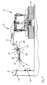
- a run as a tracked vehicle 1 Pistennostintz according to FIG. 1 is used for the preparation of ski slopes.
- the tracked vehicle 1 has in a fundamentally known manner behind a driver's cab on a functional platform on which a winch 2 is mounted in the illustrated embodiment.
- the winch 2 is provided with a according to the illustration of FIG. 1 abkragenden side of the tracked vehicle 1 winch 3, in which a winch rope 5 is guided, which protrudes to a front end 6 of the winch arm 3.
- the winch arm 3 is rotatably or pivotally driven about a vehicle vertical axis 4 by a hydraulic motor, not shown, and can be pivoted by means of a hydraulic cylinder 18 about a tilting axis 19 shown in FIG.
- a post 9 designed as a fixed anchor part is provided, which is equipped by way of example both with a cable loop 10 laid around the pile 9 and with a retaining bracket 11.
- Such a pile 9 is typically mounted above a ski slope to be prepared with the tracked vehicle 1 and allows a transmission of traction from the winch 2 of the tracked vehicle 1 to a ground.
- a considerable part of the drive power of the tracked vehicle 1 can be transmitted via the winch cable 5 and does not have to be introduced via the tracks 12 into the substrate to be prepared.
- a load on the ground can be reduced by the tracked vehicle 1 and a quality of the slope preparation can be increased.
- the guide member 7 In order to enable a remotely controlled, in particular from the driver's cab of the tracked vehicle 1, coupling and uncoupling of the winch cable 5 from the cable loop 10 or the retaining bracket 11, the guide member 7 according to the invention is attached to an end region of the winch arm 3 facing away from the tracked vehicle 1.
- the guide member 7 is pivotally mounted on the winch arm 3 about a pivot axis 13 oriented in the horizontal direction, wherein the pivot axis 13 is arranged coaxially to a rotation axis of a guide roller 14.
- the guide member 7 is shown in Figs. 1 to 3 in a lower pivot position, which is determined by a pivot stop, not shown.
- a pivoting of the guide member 7 clockwise in FIG. 1 upward is possible to ensure self-tracking angle adjustment of the guide member 7 and the guided therein winch 5 to different operating conditions of the tracked vehicle 1 when using the winch rope 5.
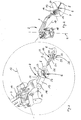
- the guide member 7, which is composed of several components, has in the side view of FIG. 1 an angled configuration, wherein a central axis 16 of a profile tube 15 of the guide member 7, the guide roller 14 at least almost tangentially touched to an advantageous supply of the winch rope 5 in to ensure the profile tube 15 and the guide roller 14.
- two mutually parallel limiting rollers 17 are provided, which each guide the winch cable 5 laterally.
- the profile tube 15 has a substantially circular cross section and is reinforced by laterally mounted box sections.
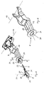
- the profile tube is widened in a funnel shape in the manner of an oval cone, as can be seen in particular from FIG. 6.
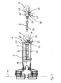
- the hook 8 is provided at the end with a correspondingly shaped oval cone-like, funnel-shaped guide surface 20, which merges into a fastening eye 21. Due to the coordinated, oval-conical surfaces of the mouth region 28 and the guide surface 20 of the hook 8, a shown in FIGS. 3, 4 and 5, predetermined by form-fitting, substantially horizontal alignment of the hook 8 relative to the guide member 7 can be ensured, the one Connecting or disconnecting the hook 8 from the anchor part 9 facilitates.
- the free end of the winch rope 5 is passed through the attachment eye 21, folded around a semicircle and fixed to the end portion of the winch cable 5 with two retaining clips 22.
- the hook 8 can move almost completely free relative to the end region of the winch cable 5, so that an introduction of bending forces into the winch cable 5 can be almost completely avoided.
- the hook 8 is associated with a non-illustrated return spring in the closing direction of the hook 8 biased pivot lever 23, which can be pivoted about a pivot axis 24 between a locking position shown on the right in FIG. 4 and an opening position shown on the left in FIG. 4.
- the pivot lever 23 is assigned a designed as a sickle-shaped opener 25 actuating means.
- the opener 25 is welded to the pivot lever 23 and protrudes in the locking position of the pivot lever 23 into a slot 26 which is provided in the guide surface 20 of the hook 8.
- the approach of the hook 8 to the deflection surface 27 and the resulting opening movement of the pivot lever 23 is effected in a simple manner by exerting a tensile force by the drive means.
- the pulling force exerted by the drive device is reduced or a pulling force pointing away from the winch arm 3 is exerted on the hook 8 so that the hook 8 moves away from the deflection surface 27 and the positive connection of the opener 25 is lifted with the deflection surface 27. Due to the deformation energy stored in the return spring The opener 25 slides on the deflection surface 27 in the direction of the locking position until the pivot lever 23 assumes the locking position shown in the left-hand illustration of FIG.
- the hook 8 is first approximated by exerting a tensile force by means of the drive means on the winch cable 5 to the deflection surface 27 of the guide member 7.
- the crescent-shaped opener 25 slides on the deflection surface 27 and leads to an opening movement of the pivot lever 23.
- the oval-conical, funnel-shaped design of the mouth 28 and the guide surface 20 of the hook 8 takes place an inevitable orientation of the hook 8 in a substantially horizontal position in which a beneficial hooking of the hook 8 in the cable loop 10 or in the headband 11 can be done solely by pivoting the winch 2 about the vehicle vertical axis 4.
- the crescent-shaped opener 25 serves as an insertion aid between the hook 8 and the cable loop 10 or headband 11. Subsequently, the tracked vehicle 1 can move away from the pile 9.
- the positive connection between opener 25 and deflection 27 automatically and inevitably canceled and the pivot lever 23 is transferred by the restoring force of the return spring in the locked position, so that the winch rope 5 safely on the post 9th is anchored and a tensile force from the tracked vehicle 1 can be done in the pile 9.
- a decoupling of the hook 8 from the pile takes place in an analogous manner.
Landscapes
- Engineering & Computer Science (AREA)
- Mechanical Engineering (AREA)
- Architecture (AREA)
- Civil Engineering (AREA)
- Structural Engineering (AREA)
- Refuge Islands, Traffic Blockers, Or Guard Fence (AREA)
- Jib Cranes (AREA)
- Load-Engaging Elements For Cranes (AREA)
Applications Claiming Priority (1)
| Application Number | Priority Date | Filing Date | Title |
|---|---|---|---|
| DE102006011906A DE102006011906B4 (de) | 2006-03-09 | 2006-03-09 | Winde für ein Fahrzeug, insbesondere für eine Pistenpflegefahrzeug |
Publications (2)
| Publication Number | Publication Date |
|---|---|
| EP1832545A2 true EP1832545A2 (fr) | 2007-09-12 |
| EP1832545A3 EP1832545A3 (fr) | 2008-07-09 |
Family
ID=37998373
Family Applications (1)
| Application Number | Title | Priority Date | Filing Date |
|---|---|---|---|
| EP07002919A Withdrawn EP1832545A3 (fr) | 2006-03-09 | 2007-02-12 | Fléche munie d un treuil pour un véhicule tout comme un véhicule destiné au couplage et/ou au découplage d'un dispositif d'ancrage sur un élément d'ancre fixe |
Country Status (4)
| Country | Link |
|---|---|
| US (1) | US7413172B2 (fr) |
| EP (1) | EP1832545A3 (fr) |
| CA (1) | CA2581760A1 (fr) |
| DE (1) | DE102006011906B4 (fr) |
Cited By (2)
| Publication number | Priority date | Publication date | Assignee | Title |
|---|---|---|---|---|
| DE102009056482A1 (de) * | 2009-12-01 | 2011-06-09 | Ludwig Giritzer | Vorrichtung zum Anhängen eines Gegenstandes |
| EP3042875B1 (fr) * | 2015-01-08 | 2017-12-27 | Ricca Andrea & C. S.n.c. | Treuil pour la foresterie, machines agricoles et similaires |
Families Citing this family (5)
| Publication number | Priority date | Publication date | Assignee | Title |
|---|---|---|---|---|
| US8220849B2 (en) | 2009-08-27 | 2012-07-17 | Beaird Iii Robert L | Device for mounting an accessory on a motor vehicle |
| US8528929B2 (en) | 2010-01-21 | 2013-09-10 | Midwest Industrial Door, Inc. | Trailer docking repositionable support |
| MX2012013357A (es) * | 2010-05-19 | 2013-04-22 | Midwest Ind Door Inc | Estabilizador de remolque. |
| CA3082649C (fr) | 2014-07-01 | 2022-12-06 | Stabilock, LLC | Dispositif de stabilisation et de retenue de remorque |
| CN116824772B (zh) * | 2023-07-14 | 2025-11-07 | 集美大学 | 一种船舶停靠防走锚辅助报警装置 |
Family Cites Families (11)
| Publication number | Priority date | Publication date | Assignee | Title |
|---|---|---|---|---|
| US1873917A (en) * | 1930-08-12 | 1932-08-23 | Ashley Lucy Chichester | Aerial mail exchange |
| US3692119A (en) * | 1971-04-23 | 1972-09-19 | Jasper J Tucker | Winch carrying snow grooming vehicle supported by skids and powered by an anchored drawline |
| FR2405206A1 (fr) * | 1977-10-04 | 1979-05-04 | Simon Francois | Equipement de levage, notamment pour travaux sur l'eau |
| US4751892A (en) * | 1987-06-26 | 1988-06-21 | Daniel Sechel | Marine standoff |
| US5474278A (en) * | 1991-12-23 | 1995-12-12 | Cleveland; Joe H. | Backpack mounted device for moving loads |
| JP2833679B2 (ja) * | 1992-09-11 | 1998-12-09 | 澄子 松山 | 重量物吊上げ用フック装置 |
| US6386514B1 (en) * | 2000-07-07 | 2002-05-14 | John D. Ray | Portable hitch-mounted winch |
| DE10203763A1 (de) * | 2002-01-25 | 2003-08-14 | Kaessbohrer Gelaendefahrzeug | Windeneinheit für ein Pistenfahrzeug |
| DE10340765B4 (de) * | 2003-09-02 | 2008-02-07 | Demag Cranes & Components Gmbh | Hakenmaulsicherung für einen Lasthaken |
| DE102004025973B4 (de) * | 2004-05-18 | 2006-10-26 | Kässbohrer Geländefahrzeug AG | Vorrichtung zum Verankern eines flexiblen Winden-Zugmittels an einem ortsfesten Ankerteil |
| DE202004008718U1 (de) * | 2004-05-28 | 2005-10-06 | Fritz, Hubert | Lasthaken |
-
2006
- 2006-03-09 DE DE102006011906A patent/DE102006011906B4/de not_active Expired - Fee Related
-
2007
- 2007-02-12 EP EP07002919A patent/EP1832545A3/fr not_active Withdrawn
- 2007-03-08 US US11/715,790 patent/US7413172B2/en not_active Expired - Fee Related
- 2007-03-08 CA CA002581760A patent/CA2581760A1/fr not_active Abandoned
Cited By (4)
| Publication number | Priority date | Publication date | Assignee | Title |
|---|---|---|---|---|
| DE102009056482A1 (de) * | 2009-12-01 | 2011-06-09 | Ludwig Giritzer | Vorrichtung zum Anhängen eines Gegenstandes |
| EP2330068B1 (fr) * | 2009-12-01 | 2013-08-14 | Ludwig Giritzer | Dispositif de remorquage d'un véhicule tout terrain |
| DE102009056482B4 (de) * | 2009-12-01 | 2019-07-25 | Ludwig Giritzer | Vorrichtung zum Anhängen eines Gegenstandes |
| EP3042875B1 (fr) * | 2015-01-08 | 2017-12-27 | Ricca Andrea & C. S.n.c. | Treuil pour la foresterie, machines agricoles et similaires |
Also Published As
| Publication number | Publication date |
|---|---|
| US20070234528A1 (en) | 2007-10-11 |
| CA2581760A1 (fr) | 2007-09-09 |
| EP1832545A3 (fr) | 2008-07-09 |
| DE102006011906B4 (de) | 2011-02-10 |
| DE102006011906A1 (de) | 2007-09-20 |
| US7413172B2 (en) | 2008-08-19 |
Similar Documents
| Publication | Publication Date | Title |
|---|---|---|
| EP1832545A2 (fr) | Fléche munie d un treuil pour un véhicule tout comme un véhicule destiné au couplage et/ou au découplage d'un dispositif d'ancrage sur un élément d'ancre fixe | |
| DE2954483C2 (fr) | ||
| US7621506B2 (en) | Multi-compartmental winch device | |
| CH631133A5 (de) | Vorrichtung zum anhaengen eines betonfertigteils an ein hebezeug. | |
| EP1602786B1 (fr) | Véhicule de préparation de piste avec un ensemble de treuil. | |
| EP2401169A2 (fr) | Collecteur de courant et système de transmission d'énergie | |
| DE10242603A1 (de) | Kraftfahrzeugsitz | |
| DE102004049969B3 (de) | Modulare Scherenbrücke sowie Verlegeeinrichtung und Verfahren zum Verlegen zerlegbarer Brücken | |
| DE202012003952U1 (de) | Brückenlegevorrichtung | |
| DE3625297C2 (fr) | ||
| DE102004025973B4 (de) | Vorrichtung zum Verankern eines flexiblen Winden-Zugmittels an einem ortsfesten Ankerteil | |
| DE202011050423U1 (de) | Sicherheitseinrichtung | |
| DE3737848C2 (de) | Vorrichtung zum Kuppeln von Fahrzeugen insbesondere von Schwerlastfahrzeugen | |
| DE1457671A1 (de) | Dreipunkthakenkupplung fuer Ackerschlepper mit hydraulisch oder dergleichen heb- undsenkbaren in ihrem Seitenabstand nach Patent.....(Patentanmeldung C 34704 III/45 a) ein- und feststellbaren Schlepparmen | |
| DE3639661C2 (de) | Automatischer Mitnehmerarm | |
| EP2330068B1 (fr) | Dispositif de remorquage d'un véhicule tout terrain | |
| EP4242162B1 (fr) | Procédé de commande d'un ensemble treuil d'une dameuse, dameuse avec dispositif de mise en oeuvre du procédé | |
| DE7009648U (de) | Vorrichtung zum befestigen eines seils an baumstaemmen und zum transportieren der baumstaemme. | |
| DE102004030996A1 (de) | Fahrzeug mit einem ausstellbaren Element der Außenhaut | |
| DE4311732C2 (de) | Abstützung für eine mobile Seilwinde | |
| DE102005019048B4 (de) | Fronthaubenanordnung und Verfahren zum Verlagern dieser | |
| EP3225744A1 (fr) | Dispositif destiné à déporter au moins un élément de faisceau souple, structure de fondation comprenant un tel dispositif et procédé destiné à déporter au moins un élément de faisceau souple | |
| DE1455626C (de) | Kupplungsvorrichtung für Fahrzeuge | |
| DE202004013345U1 (de) | Anhängerkupplung | |
| DE102022130489A1 (de) | Arbeitsbühne |
Legal Events
| Date | Code | Title | Description |
|---|---|---|---|
| PUAI | Public reference made under article 153(3) epc to a published international application that has entered the european phase |
Free format text: ORIGINAL CODE: 0009012 |
|
| AK | Designated contracting states |
Kind code of ref document: A2 Designated state(s): AT BE BG CH CY CZ DE DK EE ES FI FR GB GR HU IE IS IT LI LT LU LV MC NL PL PT RO SE SI SK TR |
|
| AX | Request for extension of the european patent |
Extension state: AL BA HR MK YU |
|
| PUAL | Search report despatched |
Free format text: ORIGINAL CODE: 0009013 |
|
| AK | Designated contracting states |
Kind code of ref document: A3 Designated state(s): AT BE BG CH CY CZ DE DK EE ES FI FR GB GR HU IE IS IT LI LT LU LV MC NL PL PT RO SE SI SK TR |
|
| AX | Request for extension of the european patent |
Extension state: AL BA HR MK RS |
|
| AKX | Designation fees paid | ||
| STAA | Information on the status of an ep patent application or granted ep patent |
Free format text: STATUS: THE APPLICATION IS DEEMED TO BE WITHDRAWN |
|
| 18D | Application deemed to be withdrawn |
Effective date: 20090110 |
|
| REG | Reference to a national code |
Ref country code: DE Ref legal event code: 8566 |