EP3042875B1 - Treuil pour la foresterie, machines agricoles et similaires - Google Patents
Treuil pour la foresterie, machines agricoles et similaires Download PDFInfo
- Publication number
- EP3042875B1 EP3042875B1 EP16150677.9A EP16150677A EP3042875B1 EP 3042875 B1 EP3042875 B1 EP 3042875B1 EP 16150677 A EP16150677 A EP 16150677A EP 3042875 B1 EP3042875 B1 EP 3042875B1
- Authority
- EP
- European Patent Office
- Prior art keywords
- rope
- drum
- control lever
- winding
- hydraulic motor
- Prior art date
- Legal status (The legal status is an assumption and is not a legal conclusion. Google has not performed a legal analysis and makes no representation as to the accuracy of the status listed.)
- Active
Links
Images


Classifications
-
- B—PERFORMING OPERATIONS; TRANSPORTING
- B66—HOISTING; LIFTING; HAULING
- B66D—CAPSTANS; WINCHES; TACKLES, e.g. PULLEY BLOCKS; HOISTS
- B66D1/00—Rope, cable, or chain winding mechanisms; Capstans
- B66D1/02—Driving gear
- B66D1/14—Power transmissions between power sources and drums or barrels
-
- B—PERFORMING OPERATIONS; TRANSPORTING
- B66—HOISTING; LIFTING; HAULING
- B66D—CAPSTANS; WINCHES; TACKLES, e.g. PULLEY BLOCKS; HOISTS
- B66D1/00—Rope, cable, or chain winding mechanisms; Capstans
- B66D1/02—Driving gear
- B66D1/08—Driving gear incorporating fluid motors
-
- B—PERFORMING OPERATIONS; TRANSPORTING
- B66—HOISTING; LIFTING; HAULING
- B66D—CAPSTANS; WINCHES; TACKLES, e.g. PULLEY BLOCKS; HOISTS
- B66D3/00—Portable or mobile lifting or hauling appliances
- B66D3/006—Power actuated devices operating on ropes, cables, or chains for hauling in a mainly horizontal direction
Definitions
- the present invention regards a winch for forestry machines, agricultural machines and the like, particularly for vertical and horizontal wood cutting machines.
- winches applied to machines thus made have the function of being able to move heavy loads such as for example trunks or stumps to be cut, to machine the operating area.
- these winches typically comprise a drum for winding and unwinding a rope that can be connected to the load.
- a rotary hydraulic motor actuates - with the shaft thereof - the drum, through a hydraulic distributor in turn actuated by a manual control lever or a remote control displaceable to a position for unwinding or winding the rope from opposite sides with respect to a central hydraulic motor stop position.
- the known winches of this type currently available in the market for the aforementioned applications, use electrical contacts for stopping the rotation of the drum both in the step of unwinding and winding the rope, or sophisticated stop mechanisms that usually act in a single direction of displacement of the rope.
- the known winches are prone to erroneous manoeuvre on the hydraulic distributor control lever by the operator, with the risk of entanglement of the rope during the unrolling step or even the snapping of the rope at the point of fixing to the drum.
- EP1832454 discloses a winch for a snow grooming machine with an electrical control unit.
- DE1116463 describes the use of a automatic winch stop arrangement that is activated as soon as the hook reaches a certain distance to the lifting boom.
- US-4358088A discloses a vehicular-mounted winch operated by the P.T.O. of the vehicle through an input shaft which drives a main shaft through a controllable clutch, an automatic one-way clutch and a controllable brake.
- EP-2363371A1 and US-4884783A are also disclosing winches operated by a motor through a hydraulic coupling or clutch.
- the object of the present invention is to overcome the aforementioned drawbacks simultaneously attaining the advantages in terms of small overall dimensions, low costs as well as ease and reliability of use even due to the absence electrical components of any kind.
- the winding of the rope by the winch is allowed in only one direction of rotation of the drum, without the possibility of erroneous manoeuvre by the operator.
- the unwinding of the rope i.e. the unrolling thereof from the drum can be exclusively carried out by pulling the rope manually.
- the lever is provided with a sliding engagement member in which the rope can be engaged in a releasable fashion when the latter is pulled manually to be unwound from the drum, so as to control the positioning of the hydraulic distributor in the aforementioned unwinding position.
- the hydraulic distributor is positioned automatically in the hydraulic motor stop position at the end of the rewinding of the rope on the drum, without requiring the actuation of the relative control lever.
- a support structure of the upright type of a wood cutting machine to which a winch according to the invention is applied is indicated with 1. It should be observed that the illustrated arrangement is provided purely by way of example, in that the winch according to the invention could be applied to machines of any kind, for example forestry machines, agricultural machines and industrial machines.
- the winch 2 comprises a rotary hydraulic motor 3 whose shaft 4 actuates a drum 5 for the winding and unwinding of a rope or cable 6, for example provided with a hook 7 at an end thereof.
- the shaft 4 of the hydraulic motor 3 is coupled to the drum 5 through a one-way engagement means for example constituted by a free wheel 8 which makes them mutually joined in rotation only in the direction corresponding to the winding of the rope 6 on the drum 5.
- the hydraulic motor 3 is actuated through a hydraulic distributor generally indicated with 9, also fixed to the support structure 1, or fixed on a different point.
- the hydraulic distributor 9 consists, in a generally conventional manner, in a spool valve displaceable, from opposite sides with respect to a central stop position of the hydraulic motor 3, respectively in a position for unwinding or winding the rope 6 relatively to the drum 5.
- the control lever 10 is provided with an engagement member 11, in form of an open ring, in which the rope 6 is slidably engaged in a releasable fashion during the unwinding thereof 5, according to the methods described hereinafter.
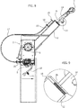
- the rope 6 extends into an inclined tubular arm 12 of the support structure 1 bearing - at the end thereof - a return pulley 13 to which there is articulated a guide member 14 of the rope 6.
- Such guide member 14 is freely rotatable between the lowered position represented in figures 1 and 2 and the raised position in figure 8 , corresponding to the complete winding of the rope 6 on the drum 5, in which the guide member 14 is aligned with the section of the rope 6 extending into the tubular arm 12.
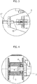
- the pulley 13 is carried by the tubular arm 12 by interposing a calibrated resilience group 15, for example constituted by disc springs, and it bears a bracket 16 to which there is connected the sheath 17 of a flexible cable transmission 18 whose one end is anchored in 19 to the end of the tubular arm 12, as better observable in figure 3 .
- the other end of the cable 18, indicated with 20, is anchored to a side of the spool of the hydraulic distributor 9 to execute the function to be outlined hereinafter.
- the winch according to the invention operates as follows.
- the hook 7 shall be firstly pulled manually and the control lever 10 of the hydraulic distributor 9 shall be simultaneously moved from the central neutral position or towards the right, i.e. in position A, so as to unwind the rope 6 from the drum 5 initially for a short section, so as to insert such rope 6 into the sliding engagement member 11 of the control lever 10 of the distributor 9, as represented in figure 7 .
- the free wheel 8 decouples the drum 5 from the hydraulic motor 2 thus, were the operator to simply actuate the lever 10 in the direction corresponding to the unwinding of the rope 6 (towards the right with respect to the central position) the drum 5 would remain stationary, thus avoiding the risk of entanglement of the rope 6 in the tubular arm 12.
- the rope 6 After unrolling the rope 6 for the required length and after anchoring it through the hook 7 to the load to be transferred, the rope 6 is removed from the engagement member 11 of the lever 10 and thus the latter may be displaced manually by the operator towards the left with respect to the central position, to be positioned in the rewinding position indicated with B in figure 1 .
- the drum 5 thus controlled in rotation by the hydraulic motor 2 rewinds the rope 6 up to positioning the load at the operating position of the machine.
- the operator may once again actuate the control lever 10 by moving it towards the left in the winding position B, to complete the total recovery of the rope 6.
- the hook 7 intercepts the guide member 14, thus causing the rotation thereof from the lowered position of figures 1 and 2 to the raised position of figure 8 in which, as mentioned, the guide member 14 is aligned with the tubular arm 12.
- the pull pressure applied to the rope 6 causes the compression of the resilient group 15, as represented in figure 9 , and the ensuing lowering of the bracket 17 due to which the cable transmission 17 automatically returns, i.e. without requiring the actuation of the control lever 10, the hydraulic distributor 9 in the central position for stopping the hydraulic motor 2.
Landscapes
- Engineering & Computer Science (AREA)
- Mechanical Engineering (AREA)
- Mechanical Control Devices (AREA)
Claims (5)
- Treuil pour machines de foresterie, machines agricoles et similaires, comprenant un tambour (5) pour l'enroulement et le déroulement d'un câble (6) prévu pour être raccordé à une charge, et un moteur hydraulique rotatif (3) dont l'arbre (4) entraîne le tambour (5) par le biais d'un distributeur hydraulique (9) ayant un levier de commande manuel, ou bien une commande à distance ou une commande électrique (10), déplaçable dans une position de déroulement ou dans une position d'enroulement sur les côtés opposés par rapport à une position d'arrêt centrale du moteur hydraulique (3), caractérisé en ce que l'arbre (4) du moteur hydraulique (3) est couplé audit tambour (5) par le biais d'un moyen de mise en prise à une voie (8) rendant ledit arbre (4) et ledit tambour (5) fixes en rotation entre eux uniquement dans la direction correspondant à l'enroulement du câble (6) sur le tambour (5), et comprenant une structure de support (1, 12) supportant une poulie de renvoi (13) et un élément (14) pour guider le câble (6) qui oscille, à la fin de l'enroulement dudit câble (6) sur le tambour (5), d'une position abaissée à une position levée afin de commander, au moyen d'une transmission de câble souple (17, 18) raccordée de manière opérationnelle audit distributeur (9), l'arrêt du moteur hydraulique (3) sans avoir à actionner ledit levier de commande (10).
- Treuil selon la revendication 1, caractérisé en ce que ledit moyen de mise en prise à une voie se compose d'une roue libre (8).
- Treuil selon la revendication 1 ou 2, caractérisé en ce que ledit élément de guidage (14) dans ladite position levée, actionne ladite transmission de câble (17, 18), suite à la traction du câble (6), par le biais d'un moyen résilient calibré (15).
- Treuil selon l'une quelconque des revendications précédentes, caractérisé en ce que ledit levier de commande (10) est configuré pour être déplacé par le câble (6) dans ladite position de déroulement.
- Treuil selon la revendication 4, caractérisé en ce que ledit levier de commande (10) est prévu avec un élément coulissant de mise en prise (11) amovible du câble (6) lorsque ce dernier est tiré manuellement pour se dérouler du tambour (5), afin de déplacer le levier de commande (10) dans ladite position de déroulement.
Applications Claiming Priority (1)
| Application Number | Priority Date | Filing Date | Title |
|---|---|---|---|
| ITTO20150011 | 2015-01-08 |
Publications (2)
| Publication Number | Publication Date |
|---|---|
| EP3042875A1 EP3042875A1 (fr) | 2016-07-13 |
| EP3042875B1 true EP3042875B1 (fr) | 2017-12-27 |
Family
ID=52633509
Family Applications (1)
| Application Number | Title | Priority Date | Filing Date |
|---|---|---|---|
| EP16150677.9A Active EP3042875B1 (fr) | 2015-01-08 | 2016-01-08 | Treuil pour la foresterie, machines agricoles et similaires |
Country Status (1)
| Country | Link |
|---|---|
| EP (1) | EP3042875B1 (fr) |
Cited By (1)
| Publication number | Priority date | Publication date | Assignee | Title |
|---|---|---|---|---|
| WO2024077362A1 (fr) * | 2022-10-11 | 2024-04-18 | Costa Luiz Henrique | Ensemble amplificateur pour treuils électriques ou similaires |
Families Citing this family (4)
| Publication number | Priority date | Publication date | Assignee | Title |
|---|---|---|---|---|
| EP3988494A1 (fr) * | 2020-10-21 | 2022-04-27 | Pisek - Vitli Krpan, d.o.o. | Treuil forestier doté d'un commutateur d'arrêt mécanique |
| EP4089045B1 (fr) * | 2021-05-12 | 2025-08-06 | Suffel Fördertechnik GmbH & Co. KG | Procédé permettant de faire fonctionner un treuil forestier et treuil forestier |
| SI26289A (sl) * | 2021-12-20 | 2023-06-30 | PIŠEK - VITLI KRPAN, d.o.o. | Mehanski vitel z mehanskim stikalom za prekinitev navijanja vrvi na boben vitla |
| SI26365A (sl) * | 2022-06-17 | 2023-12-29 | Tajfun Planina Proizvodnja Strojev, D.O.O. | Pomožni vitel, zlasti za uporabo na mobilnem hidravličnem dvigalu, in mobilno hidravlično dvigalo, opremljeno s tovrstnim vitlom |
Citations (2)
| Publication number | Priority date | Publication date | Assignee | Title |
|---|---|---|---|---|
| DE1116364B (de) * | 1959-05-13 | 1961-11-02 | Anton Lang | Vorrichtung zum Endabschalten von elektrischen Seilwinden, insbesondere von Kleinelektrozuegen |
| EP1832545A2 (fr) * | 2006-03-09 | 2007-09-12 | Kässbohrer Geländefahrzeug AG | Fléche munie d un treuil pour un véhicule tout comme un véhicule destiné au couplage et/ou au découplage d'un dispositif d'ancrage sur un élément d'ancre fixe |
Family Cites Families (5)
| Publication number | Priority date | Publication date | Assignee | Title |
|---|---|---|---|---|
| US4088305A (en) * | 1976-12-17 | 1978-05-09 | Caterpillar Tractor Co. | Brake-one way winch |
| US4358088A (en) * | 1980-10-14 | 1982-11-09 | Paccar Of Canada Ltd. | Winch drive and braking mechanism |
| US4884783A (en) * | 1988-02-12 | 1989-12-05 | Thorn, Inc. | Hoist with oil cooled brake |
| US5398911A (en) * | 1991-11-15 | 1995-03-21 | Pace Engineering Pty. Limited | Winch assembly |
| NL2004316C2 (nl) * | 2010-03-01 | 2011-09-05 | Vme B V Van Meerwijk Entpr | Lier met hydraulische koppeling. |
-
2016
- 2016-01-08 EP EP16150677.9A patent/EP3042875B1/fr active Active
Patent Citations (2)
| Publication number | Priority date | Publication date | Assignee | Title |
|---|---|---|---|---|
| DE1116364B (de) * | 1959-05-13 | 1961-11-02 | Anton Lang | Vorrichtung zum Endabschalten von elektrischen Seilwinden, insbesondere von Kleinelektrozuegen |
| EP1832545A2 (fr) * | 2006-03-09 | 2007-09-12 | Kässbohrer Geländefahrzeug AG | Fléche munie d un treuil pour un véhicule tout comme un véhicule destiné au couplage et/ou au découplage d'un dispositif d'ancrage sur un élément d'ancre fixe |
Cited By (1)
| Publication number | Priority date | Publication date | Assignee | Title |
|---|---|---|---|---|
| WO2024077362A1 (fr) * | 2022-10-11 | 2024-04-18 | Costa Luiz Henrique | Ensemble amplificateur pour treuils électriques ou similaires |
Also Published As
| Publication number | Publication date |
|---|---|
| EP3042875A1 (fr) | 2016-07-13 |
Similar Documents
| Publication | Publication Date | Title |
|---|---|---|
| EP3042875B1 (fr) | Treuil pour la foresterie, machines agricoles et similaires | |
| US10277023B2 (en) | Aerial cable laying device | |
| RU2396998C2 (ru) | Страховочное устройство | |
| US4093034A (en) | Vehicle supported winch | |
| KR20180043182A (ko) | 듀얼 모드 건축 구조물 덮개 | |
| US4170308A (en) | Hydraulic function disconnect means | |
| WO2013169680A1 (fr) | Encordage de barres parallèles pour rails mobiles | |
| EP3095748B1 (fr) | Treuil avec un mécanisme de sécurité pour l'arrêt de l' enroulement d'une corde | |
| KR200450631Y1 (ko) | 케이블 포설기 | |
| AU590828B2 (en) | Winch drag brake apparatus | |
| JP5159593B2 (ja) | 杭打機 | |
| SI24996A (sl) | Mehansko-hidravlični sistem z varnostno napravo izklopa navijanja žične vrvi vitla pri konstantni ali spremenljivi vlečni sili | |
| JP6243746B2 (ja) | 油圧集材機 | |
| AU2019202334B2 (en) | Self-raising winch boom and control systems and methods associated therewith | |
| CA2974026C (fr) | Dispositif de pose de cable aerien | |
| CN105712227A (zh) | 一种卷扬机智能离合转换设备 | |
| EP2878569B1 (fr) | Treuil avec un agencement de commande de son câble. | |
| SI24995A (sl) | Mehansko-hidravlični sistem z regulatorjem tlaka za ohranjanje konstantne moči vlečne sile vitla | |
| EP3388386A1 (fr) | Treuil forestier équipé d'un ensemble de mesure de la puissance de freinage et son procédé de fonctionnement | |
| US3958396A (en) | Lawn mower reeving system | |
| EP3024775B1 (fr) | Agencement de commande de treuil comprenant un dispositif de retenue de câble et procédé d'exploitation associé | |
| KR20190121005A (ko) | 커버 막 언와인딩 장치 | |
| AU2019231680B2 (en) | Safety pull cord for a conveyor | |
| EP2855335B1 (fr) | Treuil forestier avec dévidage commandé d'un câble de remorquage | |
| JPS60500666A (ja) | ウインチ |
Legal Events
| Date | Code | Title | Description |
|---|---|---|---|
| PUAI | Public reference made under article 153(3) epc to a published international application that has entered the european phase |
Free format text: ORIGINAL CODE: 0009012 |
|
| AK | Designated contracting states |
Kind code of ref document: A1 Designated state(s): AL AT BE BG CH CY CZ DE DK EE ES FI FR GB GR HR HU IE IS IT LI LT LU LV MC MK MT NL NO PL PT RO RS SE SI SK SM TR |
|
| AX | Request for extension of the european patent |
Extension state: BA ME |
|
| RIN1 | Information on inventor provided before grant (corrected) |
Inventor name: RICCA, ANDREA |
|
| 17P | Request for examination filed |
Effective date: 20161221 |
|
| RBV | Designated contracting states (corrected) |
Designated state(s): AL AT BE BG CH CY CZ DE DK EE ES FI FR GB GR HR HU IE IS IT LI LT LU LV MC MK MT NL NO PL PT RO RS SE SI SK SM TR |
|
| GRAP | Despatch of communication of intention to grant a patent |
Free format text: ORIGINAL CODE: EPIDOSNIGR1 |
|
| RIC1 | Information provided on ipc code assigned before grant |
Ipc: B66D 1/14 20060101AFI20170612BHEP Ipc: B66D 3/00 20060101ALI20170612BHEP Ipc: B66D 1/08 20060101ALI20170612BHEP |
|
| INTG | Intention to grant announced |
Effective date: 20170719 |
|
| GRAS | Grant fee paid |
Free format text: ORIGINAL CODE: EPIDOSNIGR3 |
|
| GRAA | (expected) grant |
Free format text: ORIGINAL CODE: 0009210 |
|
| AK | Designated contracting states |
Kind code of ref document: B1 Designated state(s): AL AT BE BG CH CY CZ DE DK EE ES FI FR GB GR HR HU IE IS IT LI LT LU LV MC MK MT NL NO PL PT RO RS SE SI SK SM TR |
|
| REG | Reference to a national code |
Ref country code: GB Ref legal event code: FG4D |
|
| REG | Reference to a national code |
Ref country code: CH Ref legal event code: EP |
|
| REG | Reference to a national code |
Ref country code: FR Ref legal event code: PLFP Year of fee payment: 3 |
|
| REG | Reference to a national code |
Ref country code: AT Ref legal event code: REF Ref document number: 958079 Country of ref document: AT Kind code of ref document: T Effective date: 20180115 |
|
| REG | Reference to a national code |
Ref country code: IE Ref legal event code: FG4D |
|
| REG | Reference to a national code |
Ref country code: DE Ref legal event code: R096 Ref document number: 602016001160 Country of ref document: DE |
|
| PG25 | Lapsed in a contracting state [announced via postgrant information from national office to epo] |
Ref country code: LT Free format text: LAPSE BECAUSE OF FAILURE TO SUBMIT A TRANSLATION OF THE DESCRIPTION OR TO PAY THE FEE WITHIN THE PRESCRIBED TIME-LIMIT Effective date: 20171227 Ref country code: FI Free format text: LAPSE BECAUSE OF FAILURE TO SUBMIT A TRANSLATION OF THE DESCRIPTION OR TO PAY THE FEE WITHIN THE PRESCRIBED TIME-LIMIT Effective date: 20171227 Ref country code: NO Free format text: LAPSE BECAUSE OF FAILURE TO SUBMIT A TRANSLATION OF THE DESCRIPTION OR TO PAY THE FEE WITHIN THE PRESCRIBED TIME-LIMIT Effective date: 20180327 |
|
| REG | Reference to a national code |
Ref country code: NL Ref legal event code: MP Effective date: 20171227 |
|
| REG | Reference to a national code |
Ref country code: LT Ref legal event code: MG4D |
|
| REG | Reference to a national code |
Ref country code: AT Ref legal event code: MK05 Ref document number: 958079 Country of ref document: AT Kind code of ref document: T Effective date: 20171227 |
|
| PG25 | Lapsed in a contracting state [announced via postgrant information from national office to epo] |
Ref country code: LV Free format text: LAPSE BECAUSE OF FAILURE TO SUBMIT A TRANSLATION OF THE DESCRIPTION OR TO PAY THE FEE WITHIN THE PRESCRIBED TIME-LIMIT Effective date: 20171227 Ref country code: GR Free format text: LAPSE BECAUSE OF FAILURE TO SUBMIT A TRANSLATION OF THE DESCRIPTION OR TO PAY THE FEE WITHIN THE PRESCRIBED TIME-LIMIT Effective date: 20180328 Ref country code: RS Free format text: LAPSE BECAUSE OF FAILURE TO SUBMIT A TRANSLATION OF THE DESCRIPTION OR TO PAY THE FEE WITHIN THE PRESCRIBED TIME-LIMIT Effective date: 20171227 Ref country code: BG Free format text: LAPSE BECAUSE OF FAILURE TO SUBMIT A TRANSLATION OF THE DESCRIPTION OR TO PAY THE FEE WITHIN THE PRESCRIBED TIME-LIMIT Effective date: 20180327 Ref country code: HR Free format text: LAPSE BECAUSE OF FAILURE TO SUBMIT A TRANSLATION OF THE DESCRIPTION OR TO PAY THE FEE WITHIN THE PRESCRIBED TIME-LIMIT Effective date: 20171227 |
|
| PG25 | Lapsed in a contracting state [announced via postgrant information from national office to epo] |
Ref country code: NL Free format text: LAPSE BECAUSE OF FAILURE TO SUBMIT A TRANSLATION OF THE DESCRIPTION OR TO PAY THE FEE WITHIN THE PRESCRIBED TIME-LIMIT Effective date: 20171227 |
|
| PG25 | Lapsed in a contracting state [announced via postgrant information from national office to epo] |
Ref country code: SK Free format text: LAPSE BECAUSE OF FAILURE TO SUBMIT A TRANSLATION OF THE DESCRIPTION OR TO PAY THE FEE WITHIN THE PRESCRIBED TIME-LIMIT Effective date: 20171227 Ref country code: ES Free format text: LAPSE BECAUSE OF FAILURE TO SUBMIT A TRANSLATION OF THE DESCRIPTION OR TO PAY THE FEE WITHIN THE PRESCRIBED TIME-LIMIT Effective date: 20171227 Ref country code: CZ Free format text: LAPSE BECAUSE OF FAILURE TO SUBMIT A TRANSLATION OF THE DESCRIPTION OR TO PAY THE FEE WITHIN THE PRESCRIBED TIME-LIMIT Effective date: 20171227 Ref country code: EE Free format text: LAPSE BECAUSE OF FAILURE TO SUBMIT A TRANSLATION OF THE DESCRIPTION OR TO PAY THE FEE WITHIN THE PRESCRIBED TIME-LIMIT Effective date: 20171227 Ref country code: CY Free format text: LAPSE BECAUSE OF FAILURE TO SUBMIT A TRANSLATION OF THE DESCRIPTION OR TO PAY THE FEE WITHIN THE PRESCRIBED TIME-LIMIT Effective date: 20171227 |
|
| PG25 | Lapsed in a contracting state [announced via postgrant information from national office to epo] |
Ref country code: SM Free format text: LAPSE BECAUSE OF FAILURE TO SUBMIT A TRANSLATION OF THE DESCRIPTION OR TO PAY THE FEE WITHIN THE PRESCRIBED TIME-LIMIT Effective date: 20171227 Ref country code: IS Free format text: LAPSE BECAUSE OF FAILURE TO SUBMIT A TRANSLATION OF THE DESCRIPTION OR TO PAY THE FEE WITHIN THE PRESCRIBED TIME-LIMIT Effective date: 20180427 Ref country code: PL Free format text: LAPSE BECAUSE OF FAILURE TO SUBMIT A TRANSLATION OF THE DESCRIPTION OR TO PAY THE FEE WITHIN THE PRESCRIBED TIME-LIMIT Effective date: 20171227 Ref country code: AT Free format text: LAPSE BECAUSE OF FAILURE TO SUBMIT A TRANSLATION OF THE DESCRIPTION OR TO PAY THE FEE WITHIN THE PRESCRIBED TIME-LIMIT Effective date: 20171227 Ref country code: IT Free format text: LAPSE BECAUSE OF FAILURE TO SUBMIT A TRANSLATION OF THE DESCRIPTION OR TO PAY THE FEE WITHIN THE PRESCRIBED TIME-LIMIT Effective date: 20171227 Ref country code: RO Free format text: LAPSE BECAUSE OF FAILURE TO SUBMIT A TRANSLATION OF THE DESCRIPTION OR TO PAY THE FEE WITHIN THE PRESCRIBED TIME-LIMIT Effective date: 20171227 |
|
| PG25 | Lapsed in a contracting state [announced via postgrant information from national office to epo] |
Ref country code: MC Free format text: LAPSE BECAUSE OF FAILURE TO SUBMIT A TRANSLATION OF THE DESCRIPTION OR TO PAY THE FEE WITHIN THE PRESCRIBED TIME-LIMIT Effective date: 20171227 |
|
| REG | Reference to a national code |
Ref country code: DE Ref legal event code: R097 Ref document number: 602016001160 Country of ref document: DE |
|
| PG25 | Lapsed in a contracting state [announced via postgrant information from national office to epo] |
Ref country code: LU Free format text: LAPSE BECAUSE OF NON-PAYMENT OF DUE FEES Effective date: 20180108 |
|
| REG | Reference to a national code |
Ref country code: IE Ref legal event code: MM4A |
|
| PLBE | No opposition filed within time limit |
Free format text: ORIGINAL CODE: 0009261 |
|
| STAA | Information on the status of an ep patent application or granted ep patent |
Free format text: STATUS: NO OPPOSITION FILED WITHIN TIME LIMIT |
|
| REG | Reference to a national code |
Ref country code: BE Ref legal event code: MM Effective date: 20180131 |
|
| PG25 | Lapsed in a contracting state [announced via postgrant information from national office to epo] |
Ref country code: BE Free format text: LAPSE BECAUSE OF NON-PAYMENT OF DUE FEES Effective date: 20180131 Ref country code: DK Free format text: LAPSE BECAUSE OF FAILURE TO SUBMIT A TRANSLATION OF THE DESCRIPTION OR TO PAY THE FEE WITHIN THE PRESCRIBED TIME-LIMIT Effective date: 20171227 |
|
| 26N | No opposition filed |
Effective date: 20180928 |
|
| PG25 | Lapsed in a contracting state [announced via postgrant information from national office to epo] |
Ref country code: IE Free format text: LAPSE BECAUSE OF NON-PAYMENT OF DUE FEES Effective date: 20180108 |
|
| PG25 | Lapsed in a contracting state [announced via postgrant information from national office to epo] |
Ref country code: SI Free format text: LAPSE BECAUSE OF FAILURE TO SUBMIT A TRANSLATION OF THE DESCRIPTION OR TO PAY THE FEE WITHIN THE PRESCRIBED TIME-LIMIT Effective date: 20171227 |
|
| REG | Reference to a national code |
Ref country code: CH Ref legal event code: PL |
|
| PG25 | Lapsed in a contracting state [announced via postgrant information from national office to epo] |
Ref country code: LI Free format text: LAPSE BECAUSE OF NON-PAYMENT OF DUE FEES Effective date: 20190131 Ref country code: CH Free format text: LAPSE BECAUSE OF NON-PAYMENT OF DUE FEES Effective date: 20190131 |
|
| PG25 | Lapsed in a contracting state [announced via postgrant information from national office to epo] |
Ref country code: MT Free format text: LAPSE BECAUSE OF NON-PAYMENT OF DUE FEES Effective date: 20180108 |
|
| PG25 | Lapsed in a contracting state [announced via postgrant information from national office to epo] |
Ref country code: TR Free format text: LAPSE BECAUSE OF FAILURE TO SUBMIT A TRANSLATION OF THE DESCRIPTION OR TO PAY THE FEE WITHIN THE PRESCRIBED TIME-LIMIT Effective date: 20171227 |
|
| PG25 | Lapsed in a contracting state [announced via postgrant information from national office to epo] |
Ref country code: PT Free format text: LAPSE BECAUSE OF FAILURE TO SUBMIT A TRANSLATION OF THE DESCRIPTION OR TO PAY THE FEE WITHIN THE PRESCRIBED TIME-LIMIT Effective date: 20171227 |
|
| PG25 | Lapsed in a contracting state [announced via postgrant information from national office to epo] |
Ref country code: HU Free format text: LAPSE BECAUSE OF FAILURE TO SUBMIT A TRANSLATION OF THE DESCRIPTION OR TO PAY THE FEE WITHIN THE PRESCRIBED TIME-LIMIT; INVALID AB INITIO Effective date: 20160108 Ref country code: MK Free format text: LAPSE BECAUSE OF NON-PAYMENT OF DUE FEES Effective date: 20171227 Ref country code: SE Free format text: LAPSE BECAUSE OF FAILURE TO SUBMIT A TRANSLATION OF THE DESCRIPTION OR TO PAY THE FEE WITHIN THE PRESCRIBED TIME-LIMIT Effective date: 20171227 |
|
| PG25 | Lapsed in a contracting state [announced via postgrant information from national office to epo] |
Ref country code: AL Free format text: LAPSE BECAUSE OF FAILURE TO SUBMIT A TRANSLATION OF THE DESCRIPTION OR TO PAY THE FEE WITHIN THE PRESCRIBED TIME-LIMIT Effective date: 20171227 |
|
| PGFP | Annual fee paid to national office [announced via postgrant information from national office to epo] |
Ref country code: GB Payment date: 20260126 Year of fee payment: 11 |
|
| PGFP | Annual fee paid to national office [announced via postgrant information from national office to epo] |
Ref country code: DE Payment date: 20260127 Year of fee payment: 11 |
|
| PGFP | Annual fee paid to national office [announced via postgrant information from national office to epo] |
Ref country code: FR Payment date: 20260126 Year of fee payment: 11 |