EP1832686A1 - Hydraulische Verriegelungsvorrichtung - Google Patents
Hydraulische Verriegelungsvorrichtung Download PDFInfo
- Publication number
- EP1832686A1 EP1832686A1 EP06118421A EP06118421A EP1832686A1 EP 1832686 A1 EP1832686 A1 EP 1832686A1 EP 06118421 A EP06118421 A EP 06118421A EP 06118421 A EP06118421 A EP 06118421A EP 1832686 A1 EP1832686 A1 EP 1832686A1
- Authority
- EP
- European Patent Office
- Prior art keywords
- hydraulically
- hydraulic
- valve
- controlled
- unloading valve
- Prior art date
- Legal status (The legal status is an assumption and is not a legal conclusion. Google has not performed a legal analysis and makes no representation as to the accuracy of the status listed.)
- Withdrawn
Links
- 239000012530 fluid Substances 0.000 claims abstract description 29
- 238000012423 maintenance Methods 0.000 description 1
- 230000007257 malfunction Effects 0.000 description 1
- 238000004519 manufacturing process Methods 0.000 description 1
Images
Classifications
-
- E—FIXED CONSTRUCTIONS
- E02—HYDRAULIC ENGINEERING; FOUNDATIONS; SOIL SHIFTING
- E02F—DREDGING; SOIL-SHIFTING
- E02F9/00—Component parts of dredgers or soil-shifting machines, not restricted to one of the kinds covered by groups E02F3/00 - E02F7/00
- E02F9/20—Drives; Control devices
- E02F9/22—Hydraulic or pneumatic drives
- E02F9/2253—Controlling the travelling speed of vehicles, e.g. adjusting travelling speed according to implement loads, control of hydrostatic transmission
-
- E—FIXED CONSTRUCTIONS
- E02—HYDRAULIC ENGINEERING; FOUNDATIONS; SOIL SHIFTING
- E02F—DREDGING; SOIL-SHIFTING
- E02F9/00—Component parts of dredgers or soil-shifting machines, not restricted to one of the kinds covered by groups E02F3/00 - E02F7/00
- E02F9/20—Drives; Control devices
- E02F9/22—Hydraulic or pneumatic drives
- E02F9/226—Safety arrangements, e.g. hydraulic driven fans, preventing cavitation, leakage, overheating
-
- E—FIXED CONSTRUCTIONS
- E02—HYDRAULIC ENGINEERING; FOUNDATIONS; SOIL SHIFTING
- E02F—DREDGING; SOIL-SHIFTING
- E02F9/00—Component parts of dredgers or soil-shifting machines, not restricted to one of the kinds covered by groups E02F3/00 - E02F7/00
- E02F9/20—Drives; Control devices
- E02F9/22—Hydraulic or pneumatic drives
- E02F9/2278—Hydraulic circuits
- E02F9/2292—Systems with two or more pumps
Definitions
- This invention relates to a hydraulic excavator, and more particularly, to a hydraulically-controlled lock apparatus for a hydraulic excavator.
- the travel of a hydraulic excavator is driven by a main pump that supplies power to a travel motor through a main control valve.
- the travel and stop of a hydraulic excavator are controlled by manipulating the main control valve through a mechanical lever.
- the main control valve needs to be manipulated so as to connect the main pump with the travel motor, which supplies power to the travel motor, so as to realize a travel mode.
- the main control valve needs to be manipulated so as to disconnect the main pump with the travel motor to lose its power, and thus to realize a stop mode.
- the travel mechanism While the hydraulic excavator is in a stop mode, the travel mechanism must be locked to prevent the main pump from connecting to the travel motor, and thus to avoid any accidents.
- the lock of a travel mechanism is achieved by a mechanical lock apparatus to lock the mechanical lever, which then locks the main control valve, and finally locks the travel mechanism.
- this type of mechanical apparatus causes the loss of fluid return pressure of the hydraulic manipulating valve, and has the disadvantages of complicated configuration, difficult manufacture and maintenance, and overall high cost.
- the objective of the present invention is to provide a hydraulically-controlled lock apparatus for the travel of a hydraulic excavator having the features of simple structure, easy manipulation, reliable operation, and high price to performance ratio, one which reduces effectively the loss of fluid return pressure of a hydraulic manipulating valve.
- a hydraulically-controlled lock apparatus for the travel of a hydraulic excavator.
- the apparatus includes a first main pump, a second main pump, a main control valve, a first travel motor, a second travel motor, and a hydraulic fluid reservoir.
- the hydraulic circuits of said first and said second main pumps to said main control valve are connected to the entrances of the hydraulically-controlled unloading valve, and the exit of said unloading valve is connected to said hydraulic fluid reservoir.
- said hydraulically-controlled unloading valve is a logic hydraulically-controlled unloading valve.
- said hydraulically-controlled unloading valve is a 2/2 way hydraulically-controlled unloading valve.
- said hydraulically-controlled unloading valve is a pilot hydraulically-controlled unloading valve.
- a hydraulically-controlled unloading valve when the travel mechanism is to be locked, a hydraulically-controlled unloading valve needs to be operated to unload the flow of the main pump to a hydraulic fluid reservoir, which enables a zero travel pressure, and thus a lock function.
- said unloading valve needs to be operated to close the unloading path from the main pump to the hydraulic fluid reservoir to realize a normal travel.
- One advantage of the present invention is that it provides a control apparatus having a simple structure and a reliable operation with fewer mounted components and a low malfunction rate.
- the other advantage of the present invention is that it reduces the loss of fluid return pressure of the main pump when the travel of a hydraulic excavator is locked.
- the hydraulically-controlled lock apparatus of the present invention is an apparatus with the features of simple structure, easy manipulation, reliable operation, and high price to performance ratio, which effectively reduces the loss of fluid return pressure of a hydraulic manipulating valve.
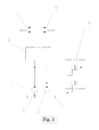
- a first main pump 6 and a second main pump 5 are driven by an engine 7.
- the main pumps 6 and 5 are connected respectively to a first travel motor 1 and a second travel motor 2 through a main control valve 8; the hydraulic circuits from the first and second main pumps 6 and 5 are also connected to entrance passages of a first logic unloading valve and a second logic unloading valve, 3, respectively.
- the exit passages of the first and the second unloading valves 3 are connected to a hydraulic fluid supply tank or a hydraulic fluid reservoir 4.
- said logic hydraulically-controlled unloading valve 3 when the hydraulic excavator is in motion, said logic hydraulically-controlled unloading valve 3 is turned off to close the unloading paths of said first and said second main pumps 6 and 5 to the hydraulic fluid reservoir 4, and thus the hydraulic fluid passes from said main pumps 6 and 5 to the main control valve 8 to the first and the second travel motors 1 and 2 to realize normal travel.
- the logic hydraulically-controlled unloading valve 3 When the travel mechanism is to be locked, the logic hydraulically-controlled unloading valve 3 is turned on to unload the flow of the said first and second main pumps 6 and 5 through the logic hydraulically-controlled unloading valve 3 to the hydraulic fluid reservoir 4, which results in a zero hydraulic pressure to the said travel motors 1 and 2, and causing their stop, and thus a lock function.
- unloading valve refers to a pressure control valve used to unload a pump and save energy when hydraulic fluid flow is not required. Unloading valves direct pump output flow directly to the hydraulic fluid reservoir at low pressure after system pressure has been reached. When the hydraulic system requires full fluid flow, fluid under pressure passes through the valve for discharge to the hydraulic system. When the system does not require full fluid flow, the excess fluid is automatically discharged from the unloading valve to the hydraulic fluid reservoir.
- the unloading valve is a logic valve or a 2/2-way valve or a pilot valve.
- Logic valves or 2/2-way valves also known as cartridge valves, have two functional ports.
- a pilot pressure hydraulically controls the flow path between the two connections.
- the logic valve has a poppet sleeve which remains in closed position with the help of a spring.
- a well seated cone of the poppet valve provides nearly zero leakage state across two ports of the valve.
- the control cover provides pilot connections, and it also encloses the cartridge valve.
- a direct control can be provided to the cartridge valve by mounting different types of pilot controls to the adjacent manifold face or to the control cover.
- the direct control of the cartridge valve's switching function can be achieved by using a pilot valve. This control is either between open or closed positions, two extreme positions or intermediate positions.
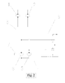
- a first main pump 6 and a second main pump 5 are driven by an engine 7.
- the main pumps 6 and 5 are connected respectively to a first travel motor 1 and a second travel motor 2 through a main control valve 8; the hydraulic circuits from the first and second main pumps 6 and 5 are also connected to entrance passages of a first 2/2-way unloading valve and a second 2/2-way unloading valve, 9, respectively.
- the exit passages of the first and the second unloading valves 9 are connected to a hydraulic fluid reservoir 4.
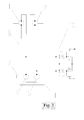
- a first main pump 6 and a second main pump 5 are driven by an engine 7.
- the main pumps 6 and 5 are connected respectively to a first travel motor 1 and a second travel motor 2 through a main control valve 8; the hydraulic circuits from the first and second main pumps 6 and 5 are also connected to entrance passages of a first pilot unloading valve and a second pilot unloading valve, 10, respectively.
- the exit passages of the first and the second unloading valves 10 are connected to a hydraulic fluid reservoir 4.
- the 2/2-way hydraulic unloading valve 9 or the pilot hydraulically-controlled unloading valve 10, respectively, are operated to unload the flow of said first and second main pumps 6 and 5 to the hydraulic fluid reservoir, which enables a zero travel pressure and thus allows to realize a lock function.
- said unloading valves 9 or 10 are operated to close the unloading paths from the first and second main pumps 6 and 5, and thus to realize normal travel.
Landscapes
- Engineering & Computer Science (AREA)
- Mining & Mineral Resources (AREA)
- Civil Engineering (AREA)
- General Engineering & Computer Science (AREA)
- Structural Engineering (AREA)
- Operation Control Of Excavators (AREA)
- Fluid-Pressure Circuits (AREA)
Applications Claiming Priority (1)
| Application Number | Priority Date | Filing Date | Title |
|---|---|---|---|
| CN06250185 | 2006-03-06 |
Publications (1)
| Publication Number | Publication Date |
|---|---|
| EP1832686A1 true EP1832686A1 (de) | 2007-09-12 |
Family
ID=36944108
Family Applications (1)
| Application Number | Title | Priority Date | Filing Date |
|---|---|---|---|
| EP06118421A Withdrawn EP1832686A1 (de) | 2006-03-06 | 2006-08-03 | Hydraulische Verriegelungsvorrichtung |
Country Status (1)
| Country | Link |
|---|---|
| EP (1) | EP1832686A1 (de) |
Cited By (2)
| Publication number | Priority date | Publication date | Assignee | Title |
|---|---|---|---|---|
| EP2674626A1 (de) * | 2012-06-12 | 2013-12-18 | HAWE Hydraulik SE | Hydraulikschaltung |
| CN113026858A (zh) * | 2021-04-07 | 2021-06-25 | 雷沃工程机械集团有限公司 | 一种提高挖掘机整平性能的控制系统及控制方法 |
Citations (7)
| Publication number | Priority date | Publication date | Assignee | Title |
|---|---|---|---|---|
| JPH02213529A (ja) * | 1989-02-14 | 1990-08-24 | Yutani Heavy Ind Ltd | 建設機械の登はんモード回路 |
| US5251440A (en) * | 1990-11-13 | 1993-10-12 | Samsung Heavy Industries Co., Ltd. | Control apparatus and method for automatically controlling a hydraulic system for heavy construction equipment |
| EP0928849A2 (de) * | 1998-01-08 | 1999-07-14 | Hitachi Construction Machinery Co., Ltd. | Pumpenstörungswarnsystem für hydraulische Baumaschinen |
| US6038859A (en) * | 1998-05-13 | 2000-03-21 | Poclain Hydraulics Industrie | Hydraulic fluid circuit having a hydraulic motor and a three-position selector for selecting the circulation of fluid |
| JP2001165109A (ja) * | 1999-12-03 | 2001-06-19 | Kubota Corp | 作業機の油圧システム |
| US20010036413A1 (en) * | 2000-03-28 | 2001-11-01 | Mcfadden Dan C. | Speed regulated oil delivery system |
| US20030037465A1 (en) * | 2001-08-22 | 2003-02-27 | Kobelco Construction Machinery Co. Ltd., | Hydraulic system for construction machine |
-
2006
- 2006-08-03 EP EP06118421A patent/EP1832686A1/de not_active Withdrawn
Patent Citations (7)
| Publication number | Priority date | Publication date | Assignee | Title |
|---|---|---|---|---|
| JPH02213529A (ja) * | 1989-02-14 | 1990-08-24 | Yutani Heavy Ind Ltd | 建設機械の登はんモード回路 |
| US5251440A (en) * | 1990-11-13 | 1993-10-12 | Samsung Heavy Industries Co., Ltd. | Control apparatus and method for automatically controlling a hydraulic system for heavy construction equipment |
| EP0928849A2 (de) * | 1998-01-08 | 1999-07-14 | Hitachi Construction Machinery Co., Ltd. | Pumpenstörungswarnsystem für hydraulische Baumaschinen |
| US6038859A (en) * | 1998-05-13 | 2000-03-21 | Poclain Hydraulics Industrie | Hydraulic fluid circuit having a hydraulic motor and a three-position selector for selecting the circulation of fluid |
| JP2001165109A (ja) * | 1999-12-03 | 2001-06-19 | Kubota Corp | 作業機の油圧システム |
| US20010036413A1 (en) * | 2000-03-28 | 2001-11-01 | Mcfadden Dan C. | Speed regulated oil delivery system |
| US20030037465A1 (en) * | 2001-08-22 | 2003-02-27 | Kobelco Construction Machinery Co. Ltd., | Hydraulic system for construction machine |
Non-Patent Citations (2)
| Title |
|---|
| PATENT ABSTRACTS OF JAPAN vol. 014, no. 514 (M - 1046) 13 November 1990 (1990-11-13) * |
| PATENT ABSTRACTS OF JAPAN vol. 2000, no. 23 10 February 2001 (2001-02-10) * |
Cited By (3)
| Publication number | Priority date | Publication date | Assignee | Title |
|---|---|---|---|---|
| EP2674626A1 (de) * | 2012-06-12 | 2013-12-18 | HAWE Hydraulik SE | Hydraulikschaltung |
| CN113026858A (zh) * | 2021-04-07 | 2021-06-25 | 雷沃工程机械集团有限公司 | 一种提高挖掘机整平性能的控制系统及控制方法 |
| CN113026858B (zh) * | 2021-04-07 | 2022-04-12 | 雷沃工程机械集团有限公司 | 一种提高挖掘机整平性能的控制系统及控制方法 |
Similar Documents
| Publication | Publication Date | Title |
|---|---|---|
| US11371535B2 (en) | Fluid pressure circuit | |
| JP2005003183A (ja) | 建設機械の油圧回路 | |
| US20030106423A1 (en) | Independent and regenerative mode fluid control system | |
| CN109958675B (zh) | 混凝土泵送设备及其液压控制系统 | |
| CN112922073B (zh) | 一种回转马达的补油系统及挖掘机 | |
| US8459019B2 (en) | System and method for pilot-operated high pressure valve | |
| CN109312858A (zh) | 用于操纵自动变速器的驻车锁的装置以及用于这种自动变速器的驻车锁机构 | |
| JPH10220409A (ja) | 方向制御弁装置 | |
| WO2022227621A1 (zh) | 一种混合动力液压系统及高空作业车 | |
| JP2005090749A (ja) | 自動圧力補償遠隔装置を備える開回路油圧伝達装置 | |
| JP2002181008A (ja) | 油圧制御装置 | |
| US20090107568A1 (en) | Apparatus Operating Hydraulic Actuator for Valve | |
| EP1832686A1 (de) | Hydraulische Verriegelungsvorrichtung | |
| US7640735B2 (en) | Auxiliary pump for hydrostatic transmission | |
| CN221141123U (zh) | 叉车行车制动自动控制系统 | |
| EP4520620A1 (de) | Hydraulische antriebseinheit für eine elektrohydraulische schaltmaschine | |
| CN100383407C (zh) | 自容式电液执行器及其集成油路块 | |
| US11905980B2 (en) | Power transfer unit with breakout friction reduction and leakage reduction | |
| CN117303266B (zh) | 叉车行车制动自动控制系统 | |
| CN105465089A (zh) | 一种舵机隔离旁通阀组 | |
| KR102706323B1 (ko) | 유압 클러치 액츄에이터 | |
| US20250180043A1 (en) | Fluid pressure circuit | |
| CN221442984U (zh) | 分配阀、定变量液压系统和装载机 | |
| KR100899599B1 (ko) | 밸브 구동용 유압제어시스템 | |
| CN218233634U (zh) | 装载机液压系统和装载机 |
Legal Events
| Date | Code | Title | Description |
|---|---|---|---|
| PUAI | Public reference made under article 153(3) epc to a published international application that has entered the european phase |
Free format text: ORIGINAL CODE: 0009012 |
|
| AK | Designated contracting states |
Kind code of ref document: A1 Designated state(s): AT BE BG CH CY CZ DE DK EE ES FI FR GB GR HU IE IS IT LI LT LU LV MC NL PL PT RO SE SI SK TR |
|
| AX | Request for extension of the european patent |
Extension state: AL BA HR MK YU |
|
| AKX | Designation fees paid | ||
| REG | Reference to a national code |
Ref country code: DE Ref legal event code: 8566 |
|
| STAA | Information on the status of an ep patent application or granted ep patent |
Free format text: STATUS: THE APPLICATION IS DEEMED TO BE WITHDRAWN |
|
| 18D | Application deemed to be withdrawn |
Effective date: 20080323 |