EP1832776A2 - Procédé et dispositif de commande et de régulation d'un embrayage automatisé - Google Patents
Procédé et dispositif de commande et de régulation d'un embrayage automatisé Download PDFInfo
- Publication number
- EP1832776A2 EP1832776A2 EP07003723A EP07003723A EP1832776A2 EP 1832776 A2 EP1832776 A2 EP 1832776A2 EP 07003723 A EP07003723 A EP 07003723A EP 07003723 A EP07003723 A EP 07003723A EP 1832776 A2 EP1832776 A2 EP 1832776A2
- Authority
- EP
- European Patent Office
- Prior art keywords
- clutch
- clutch torque
- actuator
- characteristic
- torque
- Prior art date
- Legal status (The legal status is an assumption and is not a legal conclusion. Google has not performed a legal analysis and makes no representation as to the accuracy of the status listed.)
- Withdrawn
Links
- 238000000034 method Methods 0.000 title claims description 13
- 230000008859 change Effects 0.000 claims description 10
- 230000005540 biological transmission Effects 0.000 claims description 9
- 230000001276 controlling effect Effects 0.000 claims description 6
- 230000001105 regulatory effect Effects 0.000 claims description 6
- 230000008878 coupling Effects 0.000 claims description 4
- 238000010168 coupling process Methods 0.000 claims description 4
- 238000005859 coupling reaction Methods 0.000 claims description 4
- 230000004044 response Effects 0.000 claims description 3
- 230000007246 mechanism Effects 0.000 description 3
- 238000006073 displacement reaction Methods 0.000 description 2
- 238000013519 translation Methods 0.000 description 2
- 230000014616 translation Effects 0.000 description 2
- 230000006978 adaptation Effects 0.000 description 1
- 125000004122 cyclic group Chemical group 0.000 description 1
- 238000005259 measurement Methods 0.000 description 1
- 230000002093 peripheral effect Effects 0.000 description 1
Images


Classifications
-
- F—MECHANICAL ENGINEERING; LIGHTING; HEATING; WEAPONS; BLASTING
- F16—ENGINEERING ELEMENTS AND UNITS; GENERAL MEASURES FOR PRODUCING AND MAINTAINING EFFECTIVE FUNCTIONING OF MACHINES OR INSTALLATIONS; THERMAL INSULATION IN GENERAL
- F16D—COUPLINGS FOR TRANSMITTING ROTATION; CLUTCHES; BRAKES
- F16D48/00—External control of clutches
- F16D48/06—Control by electric or electronic means, e.g. of fluid pressure
- F16D48/064—Control of electrically or electromagnetically actuated clutches
-
- F—MECHANICAL ENGINEERING; LIGHTING; HEATING; WEAPONS; BLASTING
- F16—ENGINEERING ELEMENTS AND UNITS; GENERAL MEASURES FOR PRODUCING AND MAINTAINING EFFECTIVE FUNCTIONING OF MACHINES OR INSTALLATIONS; THERMAL INSULATION IN GENERAL
- F16D—COUPLINGS FOR TRANSMITTING ROTATION; CLUTCHES; BRAKES
- F16D2500/00—External control of clutches by electric or electronic means
- F16D2500/10—System to be controlled
- F16D2500/102—Actuator
- F16D2500/1021—Electrical type
- F16D2500/1023—Electric motor
- F16D2500/1025—Electric motor with threaded transmission
-
- F—MECHANICAL ENGINEERING; LIGHTING; HEATING; WEAPONS; BLASTING
- F16—ENGINEERING ELEMENTS AND UNITS; GENERAL MEASURES FOR PRODUCING AND MAINTAINING EFFECTIVE FUNCTIONING OF MACHINES OR INSTALLATIONS; THERMAL INSULATION IN GENERAL
- F16D—COUPLINGS FOR TRANSMITTING ROTATION; CLUTCHES; BRAKES
- F16D2500/00—External control of clutches by electric or electronic means
- F16D2500/30—Signal inputs
- F16D2500/302—Signal inputs from the actuator
- F16D2500/3023—Force
-
- F—MECHANICAL ENGINEERING; LIGHTING; HEATING; WEAPONS; BLASTING
- F16—ENGINEERING ELEMENTS AND UNITS; GENERAL MEASURES FOR PRODUCING AND MAINTAINING EFFECTIVE FUNCTIONING OF MACHINES OR INSTALLATIONS; THERMAL INSULATION IN GENERAL
- F16D—COUPLINGS FOR TRANSMITTING ROTATION; CLUTCHES; BRAKES
- F16D2500/00—External control of clutches by electric or electronic means
- F16D2500/30—Signal inputs
- F16D2500/302—Signal inputs from the actuator
- F16D2500/3026—Stroke
-
- F—MECHANICAL ENGINEERING; LIGHTING; HEATING; WEAPONS; BLASTING
- F16—ENGINEERING ELEMENTS AND UNITS; GENERAL MEASURES FOR PRODUCING AND MAINTAINING EFFECTIVE FUNCTIONING OF MACHINES OR INSTALLATIONS; THERMAL INSULATION IN GENERAL
- F16D—COUPLINGS FOR TRANSMITTING ROTATION; CLUTCHES; BRAKES
- F16D2500/00—External control of clutches by electric or electronic means
- F16D2500/70—Details about the implementation of the control system
- F16D2500/702—Look-up tables
- F16D2500/70205—Clutch actuator
- F16D2500/70211—Force
-
- F—MECHANICAL ENGINEERING; LIGHTING; HEATING; WEAPONS; BLASTING
- F16—ENGINEERING ELEMENTS AND UNITS; GENERAL MEASURES FOR PRODUCING AND MAINTAINING EFFECTIVE FUNCTIONING OF MACHINES OR INSTALLATIONS; THERMAL INSULATION IN GENERAL
- F16D—COUPLINGS FOR TRANSMITTING ROTATION; CLUTCHES; BRAKES
- F16D2500/00—External control of clutches by electric or electronic means
- F16D2500/70—Details about the implementation of the control system
- F16D2500/702—Look-up tables
- F16D2500/70252—Clutch torque
- F16D2500/70264—Stroke
Definitions
- the invention relates to a method and a device for controlling and / or regulating an automated clutch, in particular in the drive train of a vehicle.
- Automated clutches are increasingly being used in modern motor vehicles.
- the control or regulation of the clutch is usually based on a characteristic which indicates the clutch torque depending on the position of an actuator.
- the actuator is moved by an actuator in the respective desired transmittable clutch torque corresponding position.
- a problem occurring in the clutch control or regulation is that in the torque characteristic one or more areas occur in which the transmissible clutch torque changes very strongly with a change in the position of the actuator, so that to the actuating member moving actuator and its Control or regulation high demands are made.
- the invention has for its object to provide a clutch control or -regelvon in which despite reduced effort in the control or regulation a high control or regulation quality is achieved.
- the claim 4 indicates a device for solving the invention task.
- an actuator whose position determines the clutch torque transmissible by the clutch is actuated to set a predetermined clutch torque according to a characteristic, the actuator corresponding to a characteristic is actuated, which in a first range of the clutch torque, the clutch torque in dependence on the position of the actuator and in a second range of the clutch torque, the clutch torque in response to the force applied by the actuator to the clutch force indicates.
- a force / travel characteristic of the actuator can be recorded, via which the clutch torque-force characteristic and the clutch torque / travel characteristic are adapted to each other.
- an inventive device for controlling and / or regulating an automated clutch in particular in the drive train of a vehicle, which controls an actuator for moving an actuator of the clutch and an electronic control device that controls the actuator according to their stored characteristics in dependence on operating parameters are in the control device stored at least two characteristics, one of which contains the transmissible clutch torque in dependence on the position of the actuator and the other the transferable clutch torque in dependence on the applied force from the actuator to the clutch, and is in the Control means provided a switching means which switches the control of the actuator from one characteristic to the other characteristic.
- one of the two characteristic curves and in another range of the transmittable clutch torque the other of the two characteristic curves is activated.
- the switching device activates, for example, the characteristic that indicates the clutch torque as a function of the force in a clutch torque range in which the change in the clutch torque is greater for a predetermined change in the position of the actuating member than in the other clutch torque range.
- the clutch may be, for example, a clutch pressed in the closed position.
- the clutch may advantageously be a clutch of a parallel shift transmission.
- parallel gearboxes are known per se and contain two partial transmissions, each of which is assigned its own clutch, wherein the parallel shift gear operates in each case in the translation, which is inserted in the partial transmission, whose clutch is closed.
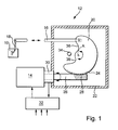
- a coupling designated as a whole by 10 is connected to an actuator, in the example illustrated an electric motor 14, via a transmission mechanism designated overall by 12.
- the transmission mechanism includes an actuator 16 which is connected directly, via further coupling links, or via a hydraulic transmission path with a clutch lever 18, the position of which determines the transmittable torque of the clutch.
- the actuator 16 is pivotally connected to a segment wheel 20 which is rotatably mounted about an axis A in a housing 22.
- the housing 22 may be rigidly connected to the housing of the clutch or a transmission housing.
- the segment wheel 20 has at a peripheral region a toothing 24 which meshes with a worm gear 28 formed on an output shaft 26 of the electric motor 14.
- an increment counter 30 is provided for detecting the rotation of the output shaft 26.
- an electronic control unit 32 For controlling the electric motor 14 is an electronic control unit 32 with. Microprocessor and associated memory devices, wherein an input to the increment counter 30 and other inputs with outputs from sensors or other control device, optionally via a bus, are connected, via which the controller 32 is supplied with relevant for the operation of the clutch data. An output of the controller 32 is connected to the electric motor 14.
- the rotatability of the segment wheel 20 is limited by at least one stop 34 against which a stop surface 36 of the segment wheel at the end of the actuation path of the actuator 16 in rotation of the segment wheel 20 in the counterclockwise direction.
- the rotatability of the segment wheel 20 in the clockwise direction is limited by the fact that a further stop surface 38 comes into abutting stop 34.
- At least one characteristic is stored, which indicates the transferable from the clutch 10 torque as a function of the position of the clutch lever 18 and the actuator 16.
- the position of the actuator 16 is known with the aid of the increment counter 30 whose count is indexed by on demand or periodically taking place Absoluteichung of the count, for example, by the segment wheel 20 is moved to rest against the stop 34, so that from the count on the Position of the actuator 16 can be closed.
- Other ways to update the characteristic again and again, are to update the closed state of the clutch or its gripping point by slip and / or torque measurement of the clutch and assignment of the count to predetermined functional states of the clutch.
- kinematic translations, type of clutch may have the dependence of the transmittable clutch torque from the path or the position of the actuator 16 most different shape.
- Figure 2 shows an example of such a characteristic curve, which is relatively flat in the range between a transmittable torque of 0 to 100 Nm and becomes steeper over 100 Nm.
- FIG. 3 shows, for this exemplary clutch, the characteristic which indicates the transmittable clutch torque as a function of the force applied to the actuating member 16 or the clutch lever 18.
- the dependence of the transmittable torque on the force in the example of the disengaging force shown, is relatively flat in the range above 100 Nm. Below this value, the course is no longer clear because the force passes through a maximum as a result of the kinematics of the clutch.
- both characteristic curves are stored in the control unit 32 and the control or regulation of the clutch takes place below a predetermined transmittable clutch torque on the basis of the clutch torque / travel characteristic of FIG. 2 and above this transmittable torque, for example 100 Nm, corresponding to the clutch torque / force characteristic of FIG.
- FIG. 4 shows the control characteristic combined from FIGS. 2 and 3 in the reverse form, ie the clutch torque is applied on the horizontal.
- the path is plotted on the left-hand ordinate, the force on the right-hand ordinate. If the clutch torque to be controlled by the control unit 32 should be less than 100 Nm, the left-hand part of the characteristic curve is used. Above 100 Nm, the right part of the characteristic is used.
- the controller 32 When working with path-controlled clutch torque, the controller 32 sets the position of the actuator 16 based on the increment counter 30.
- the transmittable clutch torque is adjusted by the force to be applied to the clutch, the electric motor 14 is driven in a voltage-controlled manner, for example, since the force exerted on the operating member 16 depends on the voltage with which the electric motor 14 is applied.
- a pressure sensor detecting the hydraulic pressure is used with the aid of which the pressure of the pressure sensor Hydraulic means is controlled. It is understood that the force applied to the clutch 10 can also be measured directly with any suitable force sensor, according to the output signal of the electric motor 14 is driven.
- the characteristic curve is used in each case in which the clutch torque to be set has a smaller dependence on the variable directly set by the actuator (position of the actuating member, force exerted on the actuating member).
- FIG. 5 shows an example of a force / displacement characteristic of a clutch whose operating force does not exceed 1400 Nm and reaches an actuating travel of about 4 mm and about 10 mm. Between these positions, the operating force passes through a minimum.
- the ranges of values and curves described above are only examples.
- the invention is suitable for all types of clutches with clutch torque / path characteristics and clutch torque / force characteristics of different gradients, wherein advantageously the slope of the clutch torque / path characteristic in a clutch torque range is large, in which the slope of the clutch torque / force characteristic is small and vice versa. Also, for reasons such as poor controllability of the voltage in a predetermined voltage range or reasons of speed advantages of a voltage control over a path control can be switched between different types of control.
- the switching can in each case in a predetermined position of the actuator 16, which is detected for example via the increment counter 30 at a predetermined voltage applied to the electric motor 14 voltage or at a predetermined transmissible torque of the clutch 10, by detecting the torque and the rotational speed a motor connected to the drive shaft of the clutch and the slip of the clutch can be detected, take place.
Landscapes
- Physics & Mathematics (AREA)
- Engineering & Computer Science (AREA)
- General Engineering & Computer Science (AREA)
- Electromagnetism (AREA)
- Fluid Mechanics (AREA)
- Mechanical Engineering (AREA)
- Hydraulic Clutches, Magnetic Clutches, Fluid Clutches, And Fluid Joints (AREA)
Applications Claiming Priority (1)
| Application Number | Priority Date | Filing Date | Title |
|---|---|---|---|
| DE102006010936 | 2006-03-09 |
Publications (2)
| Publication Number | Publication Date |
|---|---|
| EP1832776A2 true EP1832776A2 (fr) | 2007-09-12 |
| EP1832776A3 EP1832776A3 (fr) | 2012-08-08 |
Family
ID=37907773
Family Applications (1)
| Application Number | Title | Priority Date | Filing Date |
|---|---|---|---|
| EP07003723A Withdrawn EP1832776A3 (fr) | 2006-03-09 | 2007-02-23 | Procédé et dispositif de commande et de régulation d'un embrayage automatisé |
Country Status (2)
| Country | Link |
|---|---|
| US (1) | US7717248B2 (fr) |
| EP (1) | EP1832776A3 (fr) |
Families Citing this family (7)
| Publication number | Priority date | Publication date | Assignee | Title |
|---|---|---|---|---|
| US8142328B2 (en) * | 2007-07-05 | 2012-03-27 | Schaeffler Technologies AG & Co. KG | Method for controlling a starting clutch |
| DE102008036038A1 (de) * | 2008-08-01 | 2010-02-11 | Knorr-Bremse Systeme für Nutzfahrzeuge GmbH | Elektrisch betätigbarer Kupplungsausrücker und Verfahren zum Betreiben eines Kupplungsausrücksystems |
| WO2011127886A1 (fr) * | 2010-04-12 | 2011-10-20 | Schaeffler Technologies Gmbh & Co. Kg | Procédé de commande d'un accouplement automatique |
| CN102859224B (zh) * | 2010-04-26 | 2015-06-17 | 舍弗勒技术股份两合公司 | 用于适配汽车动力传动系中离合器的接触点的方法 |
| US9551414B2 (en) * | 2011-06-10 | 2017-01-24 | Caterpillar Inc. | Synchronizer engagement relative speed-based force profile |
| KR101339234B1 (ko) * | 2011-12-09 | 2013-12-09 | 현대자동차 주식회사 | 댐퍼 클러치 제어 방법 |
| US9347504B2 (en) | 2013-12-20 | 2016-05-24 | Dana Automotive Systems Group, Llc | Vehicle driveline torque managing process |
Family Cites Families (6)
| Publication number | Priority date | Publication date | Assignee | Title |
|---|---|---|---|---|
| US5850898A (en) * | 1995-09-15 | 1998-12-22 | Fahrzeugtechnik Ebern Gmbh | Method and device for the hydraulic actuation of a clutch, especially for automobiles |
| US5630773A (en) * | 1996-02-02 | 1997-05-20 | Eaton Corporation | Method and apparatus for slip mode control of automatic clutch |
| DE10103843A1 (de) * | 2001-01-30 | 2002-08-01 | Zf Sachs Ag | Auf hydraulischem Wege betätigbares Kupplungssystem |
| WO2002101258A2 (fr) * | 2001-06-13 | 2002-12-19 | Luk Lamellen Und Kupplungsbau Beteiligungs Kg | Dispositif d'actionnement d'embrayage et procede pour determiner des parametres d'embrayage |
| NO316468B1 (no) * | 2001-08-23 | 2004-01-26 | Kongsberg Automotive Asa | Clutchanordning |
| ATE418687T1 (de) * | 2006-02-16 | 2009-01-15 | Luk Lamellen & Kupplungsbau | Verfahren und vorrichtung zum nachstellen einer in einem fahrzeugantriebsstrang befindlichen, von einem aktor betätigten reibungskupplung |
-
2007
- 2007-02-20 US US11/708,503 patent/US7717248B2/en not_active Expired - Fee Related
- 2007-02-23 EP EP07003723A patent/EP1832776A3/fr not_active Withdrawn
Non-Patent Citations (1)
| Title |
|---|
| None |
Also Published As
| Publication number | Publication date |
|---|---|
| EP1832776A3 (fr) | 2012-08-08 |
| US20070209898A1 (en) | 2007-09-13 |
| US7717248B2 (en) | 2010-05-18 |
Similar Documents
| Publication | Publication Date | Title |
|---|---|---|
| EP0832370B1 (fr) | Systeme de commande d'embrayage automatique | |
| EP1820990B1 (fr) | Procédé et dispositif destinés au réglage d'un embrayage à friction actionné par un actionneur et se trouvant dans une gaine d'engrenage de véhicule | |
| DE102011051863B4 (de) | Schaltvorrichtung für ein Handschaltgetriebe | |
| DE102004050486B4 (de) | System für die Erkennung der Endposition der Bewegung der Lenkung bei "Steer by Wire" Systemen | |
| WO2000055521A1 (fr) | Systeme de commande pour actionner un embrayage de maniere automatique pendant le demarrage | |
| EP1832776A2 (fr) | Procédé et dispositif de commande et de régulation d'un embrayage automatisé | |
| EP1927777A2 (fr) | Dispositif d'actionnement hydraulique pour l'embrayage à friction d'un véhicule automobile | |
| DE19900820A1 (de) | Servounterstützungsvorrichtung für ein Getriebe | |
| DE102007021302B4 (de) | Verfahren und Vorrichtung zum Einstellen des von einer Reibungskupplung übertragenen Drehmoments | |
| EP0821178A2 (fr) | Embrayage commandé automatiquement | |
| EP1614922A2 (fr) | Méthode et dispositif pour référencer un capteur incrémentiel de position dans un dispositif d'actuation controllé électroniquement d'un embrayage | |
| DE102007008977B4 (de) | Verfahren und Vorrichtung zum Steuern und/oder Regeln einer automatisierten Kupplung | |
| DE102006013040B4 (de) | Kupplungssteuervorrichtung | |
| DE102011076542B4 (de) | Kupplungsvorrichtung und Doppelkupplungsvorrichtung | |
| DE102007029934A1 (de) | Wipphebelaktor und Verfahren zur Ermittlung von Parametern eines Elektromotors dafür | |
| WO2004065825A1 (fr) | Systeme de commande destine a un combinateur d'une boite de vitesses a engrenages | |
| DE19904022A1 (de) | Kraftfahrzeug mit einer Vorrichtung zur automatisierten Getriebebetätigung | |
| DE102010014284B4 (de) | Steuereinrichtung | |
| DE102008014531B4 (de) | Verfahren und Vorrichtung zur Adaptierung einer Kupplungs-Kennlinie | |
| DE102019215436A1 (de) | Steuern eines pneumatischen Aktuators | |
| DE102009004709B4 (de) | Doppelkupplungsgetriebe sowie Verfahren zur Steuerung eines Doppelkupplungsgetriebes | |
| DE102009008597B4 (de) | Kupplungsaktor | |
| WO2013124121A1 (fr) | Procédé de commande d'un embrayage à friction | |
| EP1832775A2 (fr) | Procédé et dispositif de surveillance du fonctionnement d'un embrayage se déplaçant automatiquement en position ouverte et se déplaçant en position fermée à l'aide d'un actionneur | |
| EP0909673A2 (fr) | Système à sûreté intégrée pour éviter la survitesse du moteur dans un vehicule avec embrayage automatisée |
Legal Events
| Date | Code | Title | Description |
|---|---|---|---|
| PUAI | Public reference made under article 153(3) epc to a published international application that has entered the european phase |
Free format text: ORIGINAL CODE: 0009012 |
|
| AK | Designated contracting states |
Kind code of ref document: A2 Designated state(s): AT BE BG CH CY CZ DE DK EE ES FI FR GB GR HU IE IS IT LI LT LU LV MC NL PL PT RO SE SI SK TR |
|
| AX | Request for extension of the european patent |
Extension state: AL BA HR MK YU |
|
| RAP1 | Party data changed (applicant data changed or rights of an application transferred) |
Owner name: SCHAEFFLER TECHNOLOGIES AG & CO. KG |
|
| PUAL | Search report despatched |
Free format text: ORIGINAL CODE: 0009013 |
|
| AK | Designated contracting states |
Kind code of ref document: A3 Designated state(s): AT BE BG CH CY CZ DE DK EE ES FI FR GB GR HU IE IS IT LI LT LU LV MC NL PL PT RO SE SI SK TR |
|
| AX | Request for extension of the european patent |
Extension state: AL BA HR MK RS |
|
| RIC1 | Information provided on ipc code assigned before grant |
Ipc: F16D 48/06 20060101AFI20120705BHEP |
|
| AKY | No designation fees paid | ||
| REG | Reference to a national code |
Ref country code: DE Ref legal event code: R108 |
|
| REG | Reference to a national code |
Ref country code: DE Ref legal event code: R108 Effective date: 20130417 |
|
| STAA | Information on the status of an ep patent application or granted ep patent |
Free format text: STATUS: THE APPLICATION IS DEEMED TO BE WITHDRAWN |
|
| 18D | Application deemed to be withdrawn |
Effective date: 20130209 |
|
| P01 | Opt-out of the competence of the unified patent court (upc) registered |
Effective date: 20230523 |