EP1832894B1 - System und Verfahren zur automatischen Verstärkungskompensation mittels Bildverarbeitung - Google Patents
System und Verfahren zur automatischen Verstärkungskompensation mittels Bildverarbeitung Download PDFInfo
- Publication number
- EP1832894B1 EP1832894B1 EP07004722.0A EP07004722A EP1832894B1 EP 1832894 B1 EP1832894 B1 EP 1832894B1 EP 07004722 A EP07004722 A EP 07004722A EP 1832894 B1 EP1832894 B1 EP 1832894B1
- Authority
- EP
- European Patent Office
- Prior art keywords
- volume data
- brightness
- agc
- lgc
- frame
- Prior art date
- Legal status (The legal status is an assumption and is not a legal conclusion. Google has not performed a legal analysis and makes no representation as to the accuracy of the status listed.)
- Active
Links
Images




Classifications
-
- B—PERFORMING OPERATIONS; TRANSPORTING
- B65—CONVEYING; PACKING; STORING; HANDLING THIN OR FILAMENTARY MATERIAL
- B65G—TRANSPORT OR STORAGE DEVICES, e.g. CONVEYORS FOR LOADING OR TIPPING, SHOP CONVEYOR SYSTEMS OR PNEUMATIC TUBE CONVEYORS
- B65G67/00—Loading or unloading vehicles
- B65G67/02—Loading or unloading land vehicles
- B65G67/04—Loading land vehicles
- B65G67/08—Loading land vehicles using endless conveyors
-
- G—PHYSICS
- G01—MEASURING; TESTING
- G01S—RADIO DIRECTION-FINDING; RADIO NAVIGATION; DETERMINING DISTANCE OR VELOCITY BY USE OF RADIO WAVES; LOCATING OR PRESENCE-DETECTING BY USE OF THE REFLECTION OR RERADIATION OF RADIO WAVES; ANALOGOUS ARRANGEMENTS USING OTHER WAVES
- G01S7/00—Details of systems according to groups G01S13/00, G01S15/00, G01S17/00
- G01S7/52—Details of systems according to groups G01S13/00, G01S15/00, G01S17/00 of systems according to group G01S15/00
- G01S7/52017—Details of systems according to groups G01S13/00, G01S15/00, G01S17/00 of systems according to group G01S15/00 particularly adapted to short-range imaging
- G01S7/52023—Details of receivers
- G01S7/52033—Gain control of receivers
-
- B—PERFORMING OPERATIONS; TRANSPORTING
- B65—CONVEYING; PACKING; STORING; HANDLING THIN OR FILAMENTARY MATERIAL
- B65G—TRANSPORT OR STORAGE DEVICES, e.g. CONVEYORS FOR LOADING OR TIPPING, SHOP CONVEYOR SYSTEMS OR PNEUMATIC TUBE CONVEYORS
- B65G13/00—Roller-ways
-
- B—PERFORMING OPERATIONS; TRANSPORTING
- B65—CONVEYING; PACKING; STORING; HANDLING THIN OR FILAMENTARY MATERIAL
- B65G—TRANSPORT OR STORAGE DEVICES, e.g. CONVEYORS FOR LOADING OR TIPPING, SHOP CONVEYOR SYSTEMS OR PNEUMATIC TUBE CONVEYORS
- B65G2207/00—Indexing codes relating to constructional details, configuration and additional features of a handling device, e.g. Conveyors
- B65G2207/08—Adjustable and/or adaptable to the article size
-
- B—PERFORMING OPERATIONS; TRANSPORTING
- B65—CONVEYING; PACKING; STORING; HANDLING THIN OR FILAMENTARY MATERIAL
- B65G—TRANSPORT OR STORAGE DEVICES, e.g. CONVEYORS FOR LOADING OR TIPPING, SHOP CONVEYOR SYSTEMS OR PNEUMATIC TUBE CONVEYORS
- B65G2814/00—Indexing codes relating to loading or unloading articles or bulk materials
- B65G2814/03—Loading or unloading means
- B65G2814/0347—Loading or unloading means for cars or linked car-trains with individual load-carriers
-
- G—PHYSICS
- G01—MEASURING; TESTING
- G01S—RADIO DIRECTION-FINDING; RADIO NAVIGATION; DETERMINING DISTANCE OR VELOCITY BY USE OF RADIO WAVES; LOCATING OR PRESENCE-DETECTING BY USE OF THE REFLECTION OR RERADIATION OF RADIO WAVES; ANALOGOUS ARRANGEMENTS USING OTHER WAVES
- G01S15/00—Systems using the reflection or reradiation of acoustic waves, e.g. sonar systems
- G01S15/88—Sonar systems specially adapted for specific applications
- G01S15/89—Sonar systems specially adapted for specific applications for mapping or imaging
- G01S15/8906—Short-range imaging systems; Acoustic microscope systems using pulse-echo techniques
- G01S15/8993—Three dimensional imaging systems
Definitions
- the present invention generally relates to image processing systems, and more particularly to an image processing system and a method for adjusting the brightness of images.
- an ultrasound diagnostic system has become an important and popular diagnostic tool due to its wide range of applications. Specifically, due to its non-invasive and non-destructive nature, the ultrasound diagnostic system has been extensively used in the medical profession. Modern high-performance ultrasound diagnostic systems and techniques are commonly used to produce two or three-dimensional (2D or 3D) diagnostic images of a target object.
- the ultrasound diagnostic system generally uses a probe including an array transducer having a plurality of transducer elements to transmit and receive ultrasound signals.
- the ultrasound diagnostic system forms an ultrasound image of the internal structures of the target object by electrically exciting the transducer elements to generate ultrasound pulses that travel into the target object.
- the ultrasound pulses produce ultrasound echoes since they are reflected from a discontinuous surface of acoustic impedance of the internal structure, which appears as discontinuities to the propagating ultrasound pulses.
- Various ultrasound echoes return to the array transducer and are converted into electrical signals, which are amplified and processed to produce ultrasound data for forming an image of the internal structure of the target object.
- the ultrasound diagnostic system is very important in the medical field since it provides physicians with real-time and high-resolution images of human internal features without the need for invasive observation techniques such as surgery.
- an ultrasound image needs to be optimized to clearly show a desirable portion for accurate diagnosis.
- the ultrasound image can be optimized by slightly adjusting the image parameters related to the brightness of an ultrasound image such as an axial gain compensation (AGC) parameter, a lateral gain compensation (LGC) parameter, a gain parameter and a dynamic range (DR) parameter.
- AGC axial gain compensation
- LGC lateral gain compensation
- DR dynamic range
- the US 2003/028107 A1 discloses a semi-invasive ultrasound imaging system for imaging biological tissue including a transesophageal probe or a transnasal, transesophageal probe connected to a two-dimensional ultrasound transducer array, a transmit beamformer, a receive beamformer, and an image generator.
- the two-dimensional transducer array is disposed on a distal portion of the probe's elongated body.
- the transmit beamformer is connected to the transducer array and is constructed to transmit several ultrasound beams over a selected pattern defined by azimuthal and elevation orientations.
- the receive beamformer is connected to the transducer array and is constructed to acquire ultrasound data from the echoes reflected over a selected tissue volume.
- the tissue volume is defined by the azimuthal and elevation orientations and a selected scan range.
- the receive beamformer is constructed to synthesize image data from the acquired ultrasound data.
- the image generator is constructed to receive the image data and generate images that are displayed on an image display. Preferably, the image generator is constructed to generate, from the image data, several orthographic projection views over the selected tissue volume.
- the US 5 524 626 describes power values of backscattered ultrasonic echoes from an interrogation region of a patient's body being stored in a 2-D envelope table.
- the region is thereby represented as a 2-D pattern of image elements.
- these elements are grouped into processing windows. After row averaging of the power values for each window, a window attenuation coefficient is generated corresponding to a decay parameter of a non-linear decay model of local attenuation of the interrogation region as a non-linear function of the average positional power values for each row in the processing window.
- the coefficients are then used to scale the power values before scan conversion and display, and thus to compensate for local attenuation.
- the invention can also test for tissue heterogeneity by first defining convergence and non-convergence criteria.
- a rationalized gain control processor then iteratively estimates the window attenuation coefficients until either criterion is met.
- the RGC processor then indicates heterogeneity of tissue in the corresponding processing window of the interrogation when the non-convergence criterion is met.
- the EP 1 005 833 A1 discloses a method and an apparatus for automating time-gain compensation (TGC) and lateral-gain compensation (LGC) based on the B-mode image data.
- the automatic gain adjustments are aimed at equalizing the mean signal intensities along the axial (for TGC) and/or lateral (for LGC) direction of the image, and suppressing any lateral band (for TGC) and/or sector (for WC) that contains mostly noise.
- the automatic TGC/LGC adjustment method is implemented in software on a digital scanner and uses a noise model of the entire B-mode processing chain from the beamformer through the B-mode processor to the back-end video processor.
- FIG. 1 is a block diagram showing an ultrasound diagnostic system constructed in accordance with one embodiment of the present invention.
- the ultrasound diagnostic system 100 includes a probe 110, an amplifier (AGC/LGC and gain controller) 120, a beamformer 130, an image signal processor 140, a volume data processor 150, an image parameter setting unit 160, a brightness adjusting unit 170, an image processor 180 and a display unit 190.
- the image signal processor 140, the volume data processor 150, the image parameter setting unit 160, the brightness adjusting unit 170 and the image processor 180 may be provided as one processor.
- the probe 110 includes a 1-dimensional or a 2-dimensional array transducer 112 including a plurality of transducer elements.
- the transmit signals which are appropriately delayed in the beamformer 130 to form an ultrasound beam, are transmitted to the array transducer 112.
- the focused ultrasound beam which is produced in response to the transmit signals, is transmitted along a scan line set in a target object (not shown).
- the probe 110 receives ultrasound echo signals reflected from the target object and converts the ultrasound echo signals into electrical signals (hereinafter referred to as "receive signals").
- the receive signals are transmitted to the amplifier 120.
- the amplifier 120 adjusts the gains of the receive signals in axial and lateral directions for axial gain compensation (AGC) and lateral gain compensation (LGC), respectively. This is to compensate for the loss in amplitude due to attenuation according to AGC/LGC parameters provided from the image parameter setting unit 160. Further, the amplifier 120 amplifies the receive signals based on the gain parameter provided from the image parameter setting unit 160.
- AGC axial gain compensation
- LGC lateral gain compensation
- the beamformer 130 provides delays to transmit signals to be transmitted to the array transducer 112 included in the probe 110 such that the ultrasound signals outputted from the array transducer 112 are focused on a focal point. Further, the beamformer 120 focuses the receive signals, which are received from the array transducer 112 included in the probe 110, in consideration of the delays with which the echo signals are arrived at each transducer element. It then outputs a focused receive beam representing the energy level of the ultrasound echo signals reflected from the focal point.
- the image signal processor 140 (e.g., a digital signal processor (DSP)) performs an envelope detection for detecting the intensities of the focused receive signals to form ultrasound image data. That is, the image signal processor 140 forms ultrasound image data based on the receive focused signals acquired from each focal point and position information of a plurality of focal points on each scan line.
- the ultrasound image data include the coordinate information of each focal point, the angle information of each scan line and the intensity information of the echo signals received at each focal point.
- the ultrasound image data may be 2D ultrasound data.
- the volume data processor 150 forms the volume data based on the ultrasound image data formed by the image signal processor 140.
- the volume data processor 150 sets a specified number of frames in the volume data.
- the frames are used for setting the AGC/LGC and gain parameters to be applied to the ultrasound image data.
- the volume data processor 150 forms the volume data 210 based on the ultrasound image data (shown in FIG. 4 ) and then sets the frames 221 to 223 in the volume data 210.
- the number of frames may be one or more (i.e., not limited to three).
- the image parameter setting unit 160 includes an AGC/LGC parameter setting unit 161 and a gain parameter setting unit 162.
- the AGC/LGC parameter setting unit 161 extracts the frames, which are set in the volume data by the volume data processor 150. Then, the AGC/LGC parameter setting unit 161 sets the optimized AGC/LGC parameters to perform AGC/LGC for the receive signals based on the characteristics of the extracted frames. That is, the AGC/LGC parameter setting unit 161 sets the optimized AGC/LGC parameters to be applied to the receive signals to compensate for the attenuation of the ultrasound echo signals in the axial and lateral directions.
- the function and operation of the AGC/LGC parameter setting unit 161 will be described in detail with reference to FIGS. 3 and 4 .
- the gain parameter setting unit 162 sets a gain parameter for controlling the gain of the ultrasound image data based on the characteristics of the frames extracted from the volume data. That is, the gain parameter setting unit 162 sets the gain parameter for adjusting the entire gain of the 2D ultrasound images.
- the function and operation of the gain parameter setting unit 162 will be described in detail with reference to FIG. 5 .
- the brightness adjusting unit 170 analyzes a histogram of volume data formed based on the ultrasound image data obtained by applying the optimized AGC/LGC and gain parameters to the receive signals, thereby detecting the characteristic value of pixel intensities. Then, the brightness adjusting unit 170 sets a dynamic range (DR) parameter for adjusting the brightness of the volume data based on the detected characteristic value of the pixel intensities.
- the characteristic value of the pixel intensities may include a mean value, a median value, a maximum value, a minimum value, a standard deviation and a variance of the pixel intensities. The function and operation of the brightness adjusting unit 170 will be described in detail with reference to FIGS. 6 and 7 .
- the image processor 180 forms the ultrasound images based on the volume data formed by the volume data processor 150.
- the image processor 180 includes a 2D image processor and a 3D image processor (not shown).
- the 2D image processor forms the 2D ultrasound images based on the frames set in the volume data by the volume data processor 150, wherein the planes were obtained by applying the optimized AGC/LGC and gain parameters to the receive signals.
- the 3D image processor forms a 3D ultrasound image based on the volume data, the brightness of which has been adjusted by the brightness adjusting unit 170.
- the ultrasound images provided from the image processor 180 are displayed in the display unit 190.
- FIG. 2 is a flowchart showing a process of processing an ultrasound image in accordance with one embodiment of the present invention.
- the image signal processor 140 forms the ultrasound image data based on the receive signals received from the probe 110 at step S102.
- the volume data processor 150 forms the volume data based on the ultrasound image data at step S104.
- the volume data processor sets a specified number of frames in the volume data and then extracts the frames set in the volume data at step S106.
- the AGC/LGC parameter setting unit 161 sets optimized AGC/LGC parameters based on the characteristics of the extracted frames at step S108.
- the step S108 will be described in detail with reference to FIGS. 3 and 4 .
- the gain parameter setting unit 162 sets an optimized gain parameter based on the characteristics of the extracted frames at step S110.
- the step S110 will be described in detail with reference to FIG. 5 .
- the amplifier 120 performs AGC/LGC upon the receive signals based on the optimized AGC/LGC parameters and then amplifies the receive signals based on the optimized gain parameter at step S112.
- the image signal processor 140 forms the ultrasound image data based on the receive signals obtained by applying the optimized AGC/LGC and gain parameters thereto at step S114.
- the volume data processor 150 forms the volume data based on the ultrasound image data at step S116.
- the brightness adjusting unit 170 adjusts the brightness of the volume data at step S118.
- the step S118 will be described in detail with reference to FIG. 6 .
- the image processor 180 forms the ultrasound images (i.e., 2D and 3D ultrasound images). The formed ultrasound images are displayed in the display unit 190 at step S122.
- FIG. 3 is a flowchart showing a process of setting AGC/LGC parameters in accordance with one embodiment of the present invention.
- FIG. 4 is an exemplary diagram showing the volume data and frames set in the volume data in accordance with one embodiment of the present invention.
- the AGC/LGC parameter setting unit 161 segments the frames 221 to 223 extracted from the volume data 210 into a plurality of regions, respectively, at step S210.
- the frames 221 to 223 are segmented in a vertical direction of the frames 221 to 223 displayed in the display unit 190.
- the frames 221 to 223 are segmented in a horizontal direction of the frames 221 to 223 displayed in the display unit 190.
- the AGC/LGC parameter setting unit 161 detects the pixels at the same depth from each vertically-segmented region for setting an AGC parameter at step S220. Also, the AGC/LGC parameter setting unit 161 detects the pixels at the same scanline from each horizontally-segmented region for setting an LGC parameter (step S230).
- the AGC/LGC parameter setting unit 161 computes the intensity characteristic values of the detected pixels at step S240.
- the intensity characteristic values may include a mean value, a median value, a maximum value, a minimum value, a standard deviation, a variance and the like of the detected pixel intensities. Then, the AGC/LGC parameter setting unit 161 obtains the profiles of the pixel intensities for respective regions based on the intensity characteristic values at step S250.
- the profiles include the vertical profiles for the AGC parameter and the horizontal profiles for the LGC parameter.
- the AGC/LGC parameter setting unit 161 models the profiles in a straight line at step S260. Such modeling may be carried out by using a Least Squares Fit method.
- the AGC/LGC parameter setting unit 161 selects a specified number of profiles with a relatively gentle gradient by analyzing the gradients of the modeled profiles at step S270.
- the gradient of the modeled profile represents the brightness attenuation of the ultrasound image in a depth direction or a lateral direction. For example, the gradient of the profile is relatively steep in a dark region of the ultrasound image.
- the gradient of the modeled horizontal profile represents the brightness of the pixels at the same depth in the ultrasound image. When the ultrasound image shows a heart in a lateral direction, there is a tendency that a central portion is bright and both end portions are dark. Therefore, the AGC/LGC parameter setting unit 161 selects a specified number of profiles with a gentle gradient in consideration of such characteristics.
- the AGC/LGC parameter setting unit 161 forms representative vertical and horizontal profiles showing the brightness attenuation of the extracted frames based on the selected profiles at step S280. Specifically, the AGC/LGC parameter setting unit 161 calculates the mean gradient of the selected profiles, respectively, and sets the profiles having the mean gradient as representative profiles. Finally, the AGC/LGC parameter setting unit 161 sets the AGC/LGC parameters based on the representative profiles at step S290.
- FIG. 5 is a flowchart showing a process of setting a gain parameter in accordance with the embodiment of the present invention.
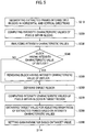
- the gain processor 162 segments the extracted frames into multiple blocks in horizontal and vertical directions at step S310. It then computes the mean brightness of the pixels within each block, which represents the brightness characteristic of each block at step S320. Also, the median value, maximum value, minimum value, standard deviation and variance of brightness of pixels within each block may be computed instead of the mean brightness for representing the brightness characteristic of each block.
- the gain parameter setting unit 162 analyzes the computed mean brightness at each block at step S330 and checks whether at least one block corresponding to outlier exists in the segmented blocks at step S340. If an arbitrary block has a mean brightness greater than a threshold, then the block is considered as the outlier representing a noise block. If it is determined that the block corresponding to the outlier exists in the segmented blocks at step S340, then the gain parameter setting unit 162 removes the block corresponding to the outlier at step S350.
- the gain parameter setting unit 162 defines a brightness range of the residual blocks except the removed block as a brightness range of typical soft tissues. On the other hand, if it is determined that there is no block corresponding to the outlier at step S340, then the gain parameter setting unit 162 defines a bright range of all blocks as a brightness range of typical soft tissues at step S360.
- the gain parameter setting unit 162 computes the mean brightness of the entire blocks within the brightness range of the typical soft tissues at step S370.
- the gain parameter setting unit 162 compares the computed means brightness with a reference mean brightness, which is previously set and stored at step S380. Finally, the gain parameter setting unit 162 sets an optimized gain parameter based on the comparison result at step S390.
- FIG. 6 is a flowchart showing a process of adjusting the brightness of volume data in accordance with one embodiment of the present invention.
- FIG. 7 illustrates a brightness adjustment function in accordance with one embodiment of the present invention.
- the brightness adjusting unit 170 analyzes a histogram of the volume data at step S410. Also, in accordance with another embodiment of the present invention, the brightness adjusting unit 170 may analyze a histogram of a frame extracted from the volume data instead of analyzing the histogram of the volume data for reducing an analysis time.
- the brightness adjusting unit 170 analyzes the histogram of the volume data, thereby obtaining the intensity characteristic values at step S420. Specially, the brightness adjusting unit 170 obtains the maximum intensity of pixels in the volume data as an intensity characteristic value. As shown in FIG. 7 , the brightness adjusting unit 170 obtains a brightness adjustment function 310 for adjusting the brightness of the volume data based on the maximum intensity of the pixels at step S430.
- the ideal max intensity is previously calculated and stored in accordance with the present invention.
- the brightness adjusting unit 170 adjusts the brightness of the volume data based on the brightness adjustment function 310 at step S440.
- the image quality of the 3-dimensional ultrasound image can be substantially improved. Also, the brightness of the volume data is adjusted in accordance with the present invention and the brightness of the 3D ultrasound image can be adjusted more accurately. Thus, the user can make a diagnosis more accurately and easily.
- An embodiment may be achieved in whole or in part by an image processing system, which includes: a volume data processor for forming volume data based on image signals and setting at least one frame in the volume data; an AGC/LGC parameter setting unit for setting axial gain compensation (AGC) and lateral gain compensation (LGC) parameters based on the frame; a gain parameter setting unit for setting a gain parameter based on the frame; an amplifying unit for performing AGC/LGC upon image signals based on the AGC/LGC parameters and amplifying the image signals based on the gain parameter to provide amplified image signals; a brightness adjusting unit for analyzing intensities of pixels included in the volume data formed based on the amplified image signals and based thereupon, adjusting brightness of the volume data based on the analysis result; and an image processor for forming images based on the frame and the brightness-adjusted volume data.
- AGC axial gain compensation
- LGC lateral gain compensation
- an image processing method comprising: a) forming volume data based on image signals; b) setting at least one frame in the volume data and extracting the frame; c) setting axial gain compensation (AGC) and lateral gain compensation (LGC) parameters based on the extracted frame; d) setting a gain parameter based on the extracted frame; e) performing AGC/LGC upon image signals based on the AGC/LGC parameters and amplifying the image signals based on the gain parameter to provide amplified image signals; f) forming volume data based on the amplified image signal; g) computing an intensity characteristic value of the volume data and adjusting brightness of the volume data based on the computed intensity characteristic value; and h) forming images based on the frame and the brightness-adjusted volume data.
- AGC axial gain compensation
- LGC lateral gain compensation
Landscapes
- Engineering & Computer Science (AREA)
- Computer Networks & Wireless Communication (AREA)
- Physics & Mathematics (AREA)
- General Physics & Mathematics (AREA)
- Radar, Positioning & Navigation (AREA)
- Remote Sensing (AREA)
- Aviation & Aerospace Engineering (AREA)
- Mechanical Engineering (AREA)
- Ultra Sonic Daignosis Equipment (AREA)
- Image Processing (AREA)
- Image Analysis (AREA)
- Closed-Circuit Television Systems (AREA)
Claims (16)
- Ultraschallbildverarbeitungssystem, welches Folgendes aufweist:einen Volumendatenprozessor (150), der dafür vorgesehen ist, Volumendaten basierend auf Ultraschallbildsignalen zu erzeugen und wenigstens einen Rahmen in den Volumendaten festzulegen;eine Axial-Steigerungs-Kompensations-/Lateral-Steigerungs-Kompensations-, AGC/LGC-Parametereinstelleinheit (161), die dafür vorgesehen ist, AGC/LGC-Parameter basierend auf dem Rahmen festzulegen;eine Steigerungs-Parameter-Festlegeeinheit (162), die dafür vorgesehen ist, einen Steigerungs-Parameter basierend auf dem Rahmen festzulegen;eine Verstärkungseinheit (120), die dafür vorgesehen ist, AGC/LGC an von einem Messkopf (110) ausgegebenen Empfangssignalen basierend auf den AGC/LGC-Parametern durchzuführen und die Empfangssignale basierend auf dem Steigerungs-Parameter zu verstärken, um verstärkte Ultraschallbildsignale zur Verfügung zu stellen;eine Helligkeitseinstelleinheit (170), die dafür vorgesehen ist, Intensitäten von Pixeln zu analysieren, die in Volumendaten enthalten sind, die basierend auf den verstärkten Ultraschallbildsignalen erzeugt werden und darauf basieren, die Helligkeit der Volumendaten, die basierend auf den verstärkten Ultraschallbildsignalen erzeugt wurden, basierend auf dem Analyseergebnis einzustellen; undeinen Bildprozessor (180), der dafür vorgesehen ist, Bilder basierend auf den rahmen- und den helligkeitseingestellten Volumendaten zu erzeugen.
- Ultraschallbildverarbeitungssystem nach Anspruch 1, wobei die AGC/LGC-Parametereinstelleinheit (161) so arbeitet, dass sie:den Rahmensatz in den Volumendaten in eine Vielzahl von Bereichen in einer spezifizierten Richtung segmentiert;Intensitätseigenschaftswerte von Pixeln in derselben Tiefe, die von jedem Bereich detektiert werden, berechnet;vertikale Profile der Intensitätseigenschaftswerte in jedem Bereich erlangt und die vertikalen Profile in einer geraden Linie modelliert;eine vorbestimmte Anzahl an vertikalen Profilen auswählt;ein repräsentatives Profil basierend auf den ausgewählten vertikalen Profilen erzeugt; undden AGC-Parameter basierend auf dem repräsentativen Profil festlegt.
- Ultraschallbildverarbeitungssystem nach Anspruch 2, wobei die AGC/LGC-Parametereinstelleinheit (161) das repräsentative Profil so erzeugt, dass es einen durchschnittlichen Gradienten der ausgewählten vertikalen Profile aufweist.
- Ultraschallbildverarbeitungssystem nach Anspruch 1, wobei die AGC/LGC-Parametereinstelleinheit (161) so arbeitet, dass sie:den Rahmensatz in den Volumendaten in eine Vielzahl von Bereichen in einer spezifizierten Richtung segmentiert;Intensitätseigenschaftswerte von Pixeln in derselben Scanlinie, die von jedem Bereich detektiert werden, berechnet;horizontale Profile der Intensitätseigenschaftswerte in jedem Bereich erlangt und die horizontalen Profile in einer Kurve modelliert;eine vorbestimmte Anzahl an horizontalen Profilen auswählt;eine repräsentative Kurve basierend auf den ausgewählten horizontalen Profilen erzeugt; undden LGC-Parameter basierend auf der repräsentativen Kurve festlegt.
- Ultraschallbildverarbeitungssystem nach Anspruch 4, wobei die AGC/LGC-Parametereinstelleinheit (161) das repräsentative Profil so erzeugt, dass es einen durchschnittlichen Gradienten der ausgewählten horizontalen Profile aufweist.
- Ultraschallbildverarbeitungssystem nach Anspruch 1, wobei die Steigerungs-Parametereinstelleinheit (162) so arbeitet, dass sie:den Rahmen in mehrere Blöcke in horizontalen und vertikalen Richtungen segmentiert und eine durchschnittliche Helligkeit der Pixel in jedem Block berechnet;Blöcke entfernt, die durchschnittliche Helligkeiten aufweisen, die größer sind als ein Grenzwert und einen Helligkeitsbereich von verbleibenden Blöcken als ein Helligkeitsbereich eines Zielobjekts definieren;einen Durchschnittswert der durchschnittlichen Helligkeit von jedem Block berechnen;den durchschnittlichen Wert mit einem Referenzwert vergleicht; undden Steigerungs-Parameter basierend auf dem Vergleichsergebnis festlegt.
- Ultraschallbildverarbeitungssystem nach Anspruch 1, wobei die Helligkeitseinstelleinheit (170) so arbeitet, dass sie:ein Histogramm der Volumendaten analysiert, um einen Intensitätseigenschaftswert der Volumendaten zu erlangen;den Intensitätseigenschaftswert mit einem Referenzwert vergleicht; eine Helligkeitseinstellfunktion basierend auf dem Vergleichsergebnis erlangt; unddie Helligkeit der Volumendaten basierend auf der Helligkeitseinstellfunktion einstellt.
- Ultraschallbildverarbeitungseinheit nach Anspruch 1, wobei der Bildprozessor (180) ein 2D-Bild basierend auf dem Rahmen und ein 3D-Bild basierend auf den Volumendaten erzeugt.
- Verfahren zur Verarbeitung eines Ultraschallbilds, welches Folgendes aufweist:a) Erzeugen von Volumendaten basierend auf Ultraschallbildsignalen;b) Festlegen wenigstens eines Rahmens in den Volumendaten und Extrahieren des Rahmens;c) Einstellen von axialen Steigungs-Kompensations-/lateral Steigungs-Kompensations-AGC/LGC-Parametern basierend auf dem extrahierten Rahmen;d) Festlegen eines Steigungs-Parameters basierend auf dem extrahierten Rahmen;e) Durchführen von AGC/LGC an von einem Messkopf (110) ausgegebenen Empfangssignalen basierend auf den AGC/LGC-Parametern und Verstärken der Empfangssignale basierend auf den Steigungs-Parametern, um verstärkte Ultraschallbildsignale zur Verfügung zu stellen;f) Erzeugen von Volumendaten basierend auf dem verstärkten Ultraschallbildsignal;g) Berechnen eines Intensitätseigenschaftswerts der Volumendaten und Einstellen der Helligkeit der Volumendaten basierend auf dem berechneten Intensitätseigenschaftswert; undh) Erzeugen von Bildern basierend auf dem Rahmen und den helligkeitseingestellten Volumendaten.
- Verfahren nach Anspruch 9, wobei der Schritt c) Folgendes aufweist:c11) Segmentieren des in den Volumendaten eingestellten Rahmens in eine Vielzahl von Bereichen in einer spezifizierten Richtung;c12) Berechnen von Intensitätseigenschaftswerten von Pixeln in derselben Tiefe, die von jedem Bereich detektiert wurden;c13) Erlangen von vertikalen Profilen der Intensitätseigenschaftswerte in jedem Bereich und Modellieren der vertikalen Profile in einer geraden Linie;c14) Auswählen einer bestimmten Anzahl an vertikalen Profilen;c15) Erzeugen eines repräsentativen Profils basierend auf den ausgewählten vertikalen Profilen; undc16) Festlegen des AGC-Parameters basierend auf dem repräsentativen Profil.
- Verfahren nach Anspruch 10, wobei der Schritt c15) Folgendes aufweist:Berechnen eines durchschnittlichen Gradientenwerts der ausgewählten vertikalen Profile;Erzeugen des repräsentativen Profils, welches den durchschnittlichen Gradienten aufweist.
- Verfahren nach Anspruch 9, wobei der Schritt c) Folgendes aufweist:C21) Segmentieren des in den Volumendaten eingestellten Rahmens in eine Vielzahl von Bereichen in einer spezifizierten Richtung;C22) Berechnen von Intensitätseigenschaftswerten von Pixeln in derselben Scanlinie, die von jedem Bereich detektiert wurden;C23) Erlangen von horizontalen Profilen der Intensitätseigenschaftswerte in jedem Bereich und Modellieren der horizontalen Profile in einer Kurve;C24) Auswählen einer bestimmten Anzahl an horizontalen Profilen;C25) Erzeugen einer repräsentativen Kurve basierend auf den ausgewählten horizontalen Profilen; undC26) Festlegen des LGC-Parameters basierend auf der repräsentativen Kurve.
- Verfahren nach Anspruch 12, wobei der Schritt c25) Folgendes beinhaltet:Berechnen eines durchschnittlichen Gradientenwerts der ausgewählten horizontalen Profile;Erzeugen des repräsentativen Profils, welches den durchschnittlichen Gradienten aufweist.
- Verfahren nach Anspruch 9, wobei der Schritt d) Folgendes beinhaltet:d1) Segmentieren des Rahmens in mehrere Blöcke in horizontalen und vertikalen Richtungen und Berechnen von durchschnittlichen Helligkeiten von Pixeln in jedem Block;d2) Entfernen von Blöcken, welche die durchschnittliche Helligkeit größer als ein Grenzwert aufweisen, und Definieren eines Helligkeitsbereichs von verbleibenden Blöcken als ein Helligkeitsbereich eines Zielobjekts;d3) Berechnen eines durchschnittlichen Werts der durchschnittlichen Helligkeit von jedem Block;d4) Vergleichen des durchschnittlichen Werts mit einem Referenzwert; undd5) Festlegen der Steigungs-Parameter basierend auf dem Vergleichsergebnis.
- Verfahren nach Anspruch 9, wobei der Schritt g) Folgendes beinhaltet:g1) Analysieren eines Histogramms der Volumendaten, um einen Intensitätseigenschaftswert der Volumendaten zu erlangen;g2) Vergleichen des Intensitätseigenschaftswerts mit einem Referenzwert;g3) Erlangen einer Helligkeitseinstellfunktion basierend auf dem Vergleichsergebnis; undg4) Einstellen der Helligkeit der Volumendaten basierend auf der Helligkeitseinstellfunktion.
- Verfahren nach Anspruch 9, wobei der Schritt h) Folgendes beinhaltet:h1) Erzeugen eines 2D-Bilds basierend auf dem Rahmen; undh2) Erzeugen eines 3D-Bilds basierend auf den Volumendaten.
Applications Claiming Priority (1)
| Application Number | Priority Date | Filing Date | Title |
|---|---|---|---|
| KR1020060022504A KR100908252B1 (ko) | 2006-03-10 | 2006-03-10 | 영상 처리 시스템 및 방법 |
Publications (3)
| Publication Number | Publication Date |
|---|---|
| EP1832894A2 EP1832894A2 (de) | 2007-09-12 |
| EP1832894A3 EP1832894A3 (de) | 2013-02-20 |
| EP1832894B1 true EP1832894B1 (de) | 2017-05-10 |
Family
ID=38123767
Family Applications (1)
| Application Number | Title | Priority Date | Filing Date |
|---|---|---|---|
| EP07004722.0A Active EP1832894B1 (de) | 2006-03-10 | 2007-03-07 | System und Verfahren zur automatischen Verstärkungskompensation mittels Bildverarbeitung |
Country Status (4)
| Country | Link |
|---|---|
| US (1) | US7787680B2 (de) |
| EP (1) | EP1832894B1 (de) |
| JP (1) | JP5040377B2 (de) |
| KR (1) | KR100908252B1 (de) |
Cited By (1)
| Publication number | Priority date | Publication date | Assignee | Title |
|---|---|---|---|---|
| US10825215B2 (en) | 2017-03-07 | 2020-11-03 | Siemens Healthcare Gmbh | Method and apparatus for generating an output image from a volume data set |
Families Citing this family (45)
| Publication number | Priority date | Publication date | Assignee | Title |
|---|---|---|---|---|
| WO2007092054A2 (en) | 2006-02-06 | 2007-08-16 | Specht Donald F | Method and apparatus to visualize the coronary arteries using ultrasound |
| EP2048512A3 (de) * | 2006-03-31 | 2009-12-09 | Aloka Co. Ltd. | Verfahren und Vorrichtung zur Ultraschallbildgebung |
| JP4945273B2 (ja) * | 2006-04-24 | 2012-06-06 | 株式会社東芝 | 超音波診断装置、及び超音波診断装置の制御プログラム |
| EP2088932B1 (de) | 2006-10-25 | 2020-04-08 | Maui Imaging, Inc. | Verfahren und vorrichtung zur herstellung von ultraschallbildern mithilfe mehrerer öffnungen |
| KR101028354B1 (ko) * | 2007-03-20 | 2011-06-14 | 주식회사 메디슨 | 초음파 영상을 형성하는 초음파 시스템 및 방법 |
| US9282945B2 (en) | 2009-04-14 | 2016-03-15 | Maui Imaging, Inc. | Calibration of ultrasound probes |
| US9339256B2 (en) | 2007-10-01 | 2016-05-17 | Maui Imaging, Inc. | Determining material stiffness using multiple aperture ultrasound |
| US9247926B2 (en) | 2010-04-14 | 2016-02-02 | Maui Imaging, Inc. | Concave ultrasound transducers and 3D arrays |
| US9788813B2 (en) | 2010-10-13 | 2017-10-17 | Maui Imaging, Inc. | Multiple aperture probe internal apparatus and cable assemblies |
| KR101659910B1 (ko) | 2008-08-08 | 2016-09-27 | 마우이 이미징, 인코포레이티드 | 다중 구경 의료용 초음파를 통한 이미징 및 애드온 시스템의 동기화 |
| JP5248961B2 (ja) * | 2008-09-18 | 2013-07-31 | パナソニック株式会社 | 超音波診断装置 |
| KR100989580B1 (ko) * | 2008-09-30 | 2010-10-25 | 주식회사 바이오넷 | 초음파 영상장치의 영상 조정방법 |
| JP5485373B2 (ja) | 2009-04-14 | 2014-05-07 | マウイ イマギング,インコーポレーテッド | 複数開口の超音波アレイ位置合せ装置 |
| KR102322776B1 (ko) | 2010-02-18 | 2021-11-04 | 마우이 이미징, 인코포레이티드 | 초음파 이미지를 구성하는 방법 및 이를 위한 다중-개구 초음파 이미징 시스템 |
| US9289191B2 (en) | 2011-10-12 | 2016-03-22 | Seno Medical Instruments, Inc. | System and method for acquiring optoacoustic data and producing parametric maps thereof |
| US8744793B2 (en) | 2010-10-20 | 2014-06-03 | Sonix, Inc. | Method and apparatus for adjusting the level of a response signal from an ultrasound transducer |
| KR101422574B1 (ko) * | 2010-11-25 | 2014-07-24 | 서강대학교산학협력단 | 초음파 진단장치 및 그 제어방법 |
| US9730587B2 (en) | 2011-11-02 | 2017-08-15 | Seno Medical Instruments, Inc. | Diagnostic simulator |
| US9743839B2 (en) | 2011-11-02 | 2017-08-29 | Seno Medical Instruments, Inc. | Playback mode in an optoacoustic imaging system |
| US11287309B2 (en) | 2011-11-02 | 2022-03-29 | Seno Medical Instruments, Inc. | Optoacoustic component utilization tracking |
| US11191435B2 (en) | 2013-01-22 | 2021-12-07 | Seno Medical Instruments, Inc. | Probe with optoacoustic isolator |
| US9814394B2 (en) | 2011-11-02 | 2017-11-14 | Seno Medical Instruments, Inc. | Noise suppression in an optoacoustic system |
| US9733119B2 (en) | 2011-11-02 | 2017-08-15 | Seno Medical Instruments, Inc. | Optoacoustic component utilization tracking |
| JP6407719B2 (ja) | 2011-12-01 | 2018-10-17 | マウイ イマギング,インコーポレーテッド | ピングベース及び多数開口ドップラー超音波を用いた運動の検出 |
| JP2015503404A (ja) | 2011-12-29 | 2015-02-02 | マウイ イマギング,インコーポレーテッド | 任意経路のmモード超音波イメージング |
| JP2015509443A (ja) | 2012-03-09 | 2015-03-30 | セノ メディカル インストルメンツ,インク. | 光音響イメージングシステムにおける統計マッピング |
| EP2833791B1 (de) | 2012-03-26 | 2022-12-21 | Maui Imaging, Inc. | Verfahren zur verbesserung der ultraschallbildqualität durch anwendung von gewichtungsfaktoren |
| CN104620128B (zh) | 2012-08-10 | 2017-06-23 | 毛伊图像公司 | 多孔径超声探头的校准 |
| CN103676827A (zh) | 2012-09-06 | 2014-03-26 | Ip音乐集团有限公司 | 用于远程控制音频设备的系统和方法 |
| US9986969B2 (en) | 2012-09-06 | 2018-06-05 | Maui Imaging, Inc. | Ultrasound imaging system memory architecture |
| WO2014160291A1 (en) | 2013-03-13 | 2014-10-02 | Maui Imaging, Inc. | Alignment of ultrasound transducer arrays and multiple aperture probe assembly |
| US9883848B2 (en) | 2013-09-13 | 2018-02-06 | Maui Imaging, Inc. | Ultrasound imaging using apparent point-source transmit transducer |
| KR102249528B1 (ko) | 2014-04-01 | 2021-05-11 | 삼성메디슨 주식회사 | 미리 저장된 그라데이션 데이터 및 영상을 이용하여 초음파 영상의 밝기를 조정하는 방법, 장치 및 시스템. |
| US10401493B2 (en) | 2014-08-18 | 2019-09-03 | Maui Imaging, Inc. | Network-based ultrasound imaging system |
| US20160157827A1 (en) * | 2014-12-03 | 2016-06-09 | General Electric Company | Methods and systems for ultrasound imaging |
| CN107613878B (zh) | 2015-03-30 | 2021-04-06 | 毛伊图像公司 | 用于检测物体运动的超声成像系统和方法 |
| KR101652723B1 (ko) * | 2015-04-10 | 2016-08-31 | 서강대학교산학협력단 | 초음파 영상 화질 개선 방법 및 이를 이용한 초음파 영상 장치 |
| KR101685823B1 (ko) * | 2015-06-18 | 2016-12-21 | 인하대학교 산학협력단 | 흉부 X―ray 영상을 위한 화질 개선 방법 및 시스템 |
| EP3371624B1 (de) * | 2015-11-02 | 2019-06-19 | Koninklijke Philips N.V. | Ultraschallsystem zur bereitstellung von ultraschallbildern mit variablen frequenzen eines volumetrischen bereichs mit einem störer- analysator |
| EP4697068A3 (de) | 2016-01-27 | 2026-04-22 | Maui Imaging, Inc. | Ultraschallbildgebung mit spärlichen arraysonden |
| WO2018023082A1 (en) * | 2016-07-28 | 2018-02-01 | Easy Life Brands LLC | Automatic flame extinguisher |
| CN106618632B (zh) * | 2016-12-14 | 2020-08-07 | 无锡祥生医疗科技股份有限公司 | 自动优化的超声成像系统及方法 |
| KR102296675B1 (ko) * | 2018-02-09 | 2021-09-02 | 지멘스 메디컬 솔루션즈 유에스에이, 인크. | 합성 영상을 생성하는 방법 및 초음파 시스템 |
| JP7724853B2 (ja) | 2020-10-21 | 2025-08-18 | マウイ イマギング,インコーポレーテッド | 多数開口超音波を用いた組織の特徴付けのためのシステム及び方法 |
| EP4236811A4 (de) | 2020-11-02 | 2024-10-09 | Maui Imaging, Inc. | Systeme und verfahren zur verbesserung der ultraschallbildqualität |
Family Cites Families (19)
| Publication number | Priority date | Publication date | Assignee | Title |
|---|---|---|---|---|
| US4733668A (en) * | 1979-09-04 | 1988-03-29 | North American Philips Corporation | Method and apparatus for compensation during ultrasound examination |
| JPS58183151A (ja) * | 1982-04-21 | 1983-10-26 | 株式会社東芝 | 超音波診断装置 |
| US5257624A (en) * | 1991-10-25 | 1993-11-02 | Hewlett-Packard Company | Gain control for ultrasound system |
| US5313948A (en) * | 1991-11-28 | 1994-05-24 | Aloka Co., Ltd. | Ultrasonic diagnostic apparatus |
| JP3245225B2 (ja) * | 1992-08-10 | 2002-01-07 | フクダ電子株式会社 | 超音波診断装置 |
| JPH06133967A (ja) | 1992-10-29 | 1994-05-17 | Olympus Optical Co Ltd | 超音波診断装置 |
| US5524626A (en) | 1995-06-30 | 1996-06-11 | Siemens Medical Systems, Inc. | System and method for determining local attenuation for ultrasonic imaging |
| JP3610129B2 (ja) * | 1995-09-18 | 2005-01-12 | ジーイー横河メディカルシステム株式会社 | 画像表示方法および装置並びに超音波診断装置 |
| JPH10234726A (ja) * | 1997-02-26 | 1998-09-08 | Shimadzu Corp | 超音波診断装置 |
| US6224552B1 (en) * | 1998-10-01 | 2001-05-01 | Atl Ultrasound | Ultrasonic diagnostic imaging system with reduced spatial compounding seam artifacts |
| JP2000139914A (ja) * | 1998-11-04 | 2000-05-23 | Aloka Co Ltd | 超音波診断装置 |
| US6102859A (en) * | 1998-12-01 | 2000-08-15 | General Electric Company | Method and apparatus for automatic time and/or lateral gain compensation in B-mode ultrasound imaging |
| US6572547B2 (en) | 2001-07-31 | 2003-06-03 | Koninklijke Philips Electronics N.V. | Transesophageal and transnasal, transesophageal ultrasound imaging systems |
| US6743174B2 (en) * | 2002-04-01 | 2004-06-01 | Koninklijke Philips Electronics N.V. | Ultrasonic diagnostic imaging system with automatically controlled contrast and brightness |
| US6666824B2 (en) * | 2002-04-01 | 2003-12-23 | Koninklijke Philips Electronics N.V. | System and method of dynamic automatic sensing of available dynamic range |
| US6679844B2 (en) * | 2002-06-20 | 2004-01-20 | Acuson Corporation | Automatic gain compensation for multiple mode or contrast agent imaging |
| JP4482289B2 (ja) * | 2003-06-09 | 2010-06-16 | ジーイー・メディカル・システムズ・グローバル・テクノロジー・カンパニー・エルエルシー | 流れ画像表示方法および超音波診断装置 |
| JP2006020777A (ja) * | 2004-07-07 | 2006-01-26 | Aloka Co Ltd | 超音波診断装置 |
| US7645236B2 (en) * | 2005-06-28 | 2010-01-12 | Siemens Medical Solutions Usa, Inc. | Ultrasound imaging system having motion adaptive gain |
-
2006
- 2006-03-10 KR KR1020060022504A patent/KR100908252B1/ko not_active Expired - Lifetime
-
2007
- 2007-03-07 EP EP07004722.0A patent/EP1832894B1/de active Active
- 2007-03-09 JP JP2007060265A patent/JP5040377B2/ja not_active Expired - Fee Related
- 2007-03-09 US US11/684,234 patent/US7787680B2/en active Active
Cited By (1)
| Publication number | Priority date | Publication date | Assignee | Title |
|---|---|---|---|---|
| US10825215B2 (en) | 2017-03-07 | 2020-11-03 | Siemens Healthcare Gmbh | Method and apparatus for generating an output image from a volume data set |
Also Published As
| Publication number | Publication date |
|---|---|
| US20070236492A1 (en) | 2007-10-11 |
| JP5040377B2 (ja) | 2012-10-03 |
| EP1832894A2 (de) | 2007-09-12 |
| KR100908252B1 (ko) | 2009-07-20 |
| JP2007236955A (ja) | 2007-09-20 |
| EP1832894A3 (de) | 2013-02-20 |
| KR20070092407A (ko) | 2007-09-13 |
| US7787680B2 (en) | 2010-08-31 |
Similar Documents
| Publication | Publication Date | Title |
|---|---|---|
| EP1832894B1 (de) | System und Verfahren zur automatischen Verstärkungskompensation mittels Bildverarbeitung | |
| US9901323B2 (en) | Aberration correction using channel data in ultrasound imaging system | |
| CN106333707B (zh) | 超声多普勒图谱校正方法、装置及超声诊断系统 | |
| CN106028947B (zh) | 血流成像方法及系统 | |
| EP1793343B1 (de) | Bildverarbeitungssystem und Verfahren zur Verbesserung der Qualität eines Ultraschallbildes | |
| US20060094962A1 (en) | Aperture shading estimation techniques for reducing ultrasound multi-line image distortion | |
| US9743910B2 (en) | Ultrasonic diagnostic apparatus, ultrasonic image processing apparatus, medical image diagnostic apparatus, and medical image processing apparatus | |
| KR101422574B1 (ko) | 초음파 진단장치 및 그 제어방법 | |
| JP2004215987A (ja) | 超音波診断装置および超音波診断方法 | |
| JP2005152648A (ja) | 運動適応型空間合成の方法及びシステム | |
| US20050124883A1 (en) | Adaptive parallel artifact mitigation | |
| JP2000189424A (ja) | Bモ―ド超音波イメ―ジングにおける自動送信波形最適化のための方法及び装置 | |
| JP4996247B2 (ja) | 超音波診断装置 | |
| JP4320392B2 (ja) | 高歪みレート除去フィルタ処理のための方法及び装置 | |
| JP5069022B2 (ja) | 超音波撮像で使用するための正確な時間遅延推定の方法及びシステム | |
| US20230061869A1 (en) | System and methods for beamforming sound speed selection | |
| CN113348378B (zh) | 具有置信度估计的声衰减系数的超声成像 | |
| CN113316421B (zh) | 用于超声衰减系数估计的系统和方法 | |
| KR100873336B1 (ko) | 3차원 초음파 영상의 밝기 및 대조도를 자동으로 제어하는방법 및 초음파 진단 시스템 | |
| KR101652728B1 (ko) | 초음파 영상 화질 개선 방법 및 이를 이용한 초음파 영상 장치 | |
| JP2003339698A (ja) | 超音波診断装置 | |
| KR20170082554A (ko) | 이미지 이득을 조정하는 방법 및 시스템 | |
| CN100594392C (zh) | 多区彩色多普勒波束发射方法 | |
| JP4664209B2 (ja) | 超音波診断装置およびその撮像を実行する超音波イメージングプログラム | |
| JP3388954B2 (ja) | 超音波診断装置 |
Legal Events
| Date | Code | Title | Description |
|---|---|---|---|
| PUAI | Public reference made under article 153(3) epc to a published international application that has entered the european phase |
Free format text: ORIGINAL CODE: 0009012 |
|
| AK | Designated contracting states |
Kind code of ref document: A2 Designated state(s): AT BE BG CH CY CZ DE DK EE ES FI FR GB GR HU IE IS IT LI LT LU LV MC MT NL PL PT RO SE SI SK TR |
|
| AX | Request for extension of the european patent |
Extension state: AL BA HR MK YU |
|
| PUAL | Search report despatched |
Free format text: ORIGINAL CODE: 0009013 |
|
| AK | Designated contracting states |
Kind code of ref document: A3 Designated state(s): AT BE BG CH CY CZ DE DK EE ES FI FR GB GR HU IE IS IT LI LT LU LV MC MT NL PL PT RO SE SI SK TR |
|
| AX | Request for extension of the european patent |
Extension state: AL BA HR MK RS |
|
| RIC1 | Information provided on ipc code assigned before grant |
Ipc: G01S 15/89 20060101ALN20130115BHEP Ipc: G01S 7/52 20060101AFI20130115BHEP |
|
| 17P | Request for examination filed |
Effective date: 20130730 |
|
| RBV | Designated contracting states (corrected) |
Designated state(s): AT BE BG CH CY CZ DE DK EE ES FI FR GB GR HU IE IS IT LI LT LU LV MC MT NL PL PT RO SE SI SK TR |
|
| AKX | Designation fees paid |
Designated state(s): AT BE BG CH CY LI |
|
| REG | Reference to a national code |
Ref country code: DE Ref legal event code: R108 |
|
| RBV | Designated contracting states (corrected) |
Designated state(s): AT BE BG CH CY CZ DE DK EE ES FI FR GB GR HU IE IS IT LI LT LU LV MC MT NL PL PT RO SE SI SK TR |
|
| GRAP | Despatch of communication of intention to grant a patent |
Free format text: ORIGINAL CODE: EPIDOSNIGR1 |
|
| RIC1 | Information provided on ipc code assigned before grant |
Ipc: G01S 15/89 20060101ALN20161110BHEP Ipc: G01S 7/52 20060101AFI20161110BHEP |
|
| RIC1 | Information provided on ipc code assigned before grant |
Ipc: G01S 15/89 20060101ALN20161124BHEP Ipc: G01S 7/52 20060101AFI20161124BHEP |
|
| INTG | Intention to grant announced |
Effective date: 20161208 |
|
| GRAS | Grant fee paid |
Free format text: ORIGINAL CODE: EPIDOSNIGR3 |
|
| RAP1 | Party data changed (applicant data changed or rights of an application transferred) |
Owner name: SAMSUNG MEDISON CO., LTD. |
|
| GRAA | (expected) grant |
Free format text: ORIGINAL CODE: 0009210 |
|
| AK | Designated contracting states |
Kind code of ref document: B1 Designated state(s): AT BE BG CH CY CZ DE DK EE ES FI FR GB GR HU IE IS IT LI LT LU LV MC MT NL PL PT RO SE SI SK TR |
|
| REG | Reference to a national code |
Ref country code: GB Ref legal event code: FG4D |
|
| REG | Reference to a national code |
Ref country code: AT Ref legal event code: REF Ref document number: 892918 Country of ref document: AT Kind code of ref document: T Effective date: 20170515 Ref country code: CH Ref legal event code: EP |
|
| REG | Reference to a national code |
Ref country code: IE Ref legal event code: FG4D |
|
| REG | Reference to a national code |
Ref country code: DE Ref legal event code: R096 Ref document number: 602007050901 Country of ref document: DE |
|
| REG | Reference to a national code |
Ref country code: NL Ref legal event code: FP |
|
| REG | Reference to a national code |
Ref country code: LT Ref legal event code: MG4D |
|
| REG | Reference to a national code |
Ref country code: AT Ref legal event code: MK05 Ref document number: 892918 Country of ref document: AT Kind code of ref document: T Effective date: 20170510 |
|
| PG25 | Lapsed in a contracting state [announced via postgrant information from national office to epo] |
Ref country code: ES Free format text: LAPSE BECAUSE OF FAILURE TO SUBMIT A TRANSLATION OF THE DESCRIPTION OR TO PAY THE FEE WITHIN THE PRESCRIBED TIME-LIMIT Effective date: 20170510 Ref country code: LT Free format text: LAPSE BECAUSE OF FAILURE TO SUBMIT A TRANSLATION OF THE DESCRIPTION OR TO PAY THE FEE WITHIN THE PRESCRIBED TIME-LIMIT Effective date: 20170510 Ref country code: AT Free format text: LAPSE BECAUSE OF FAILURE TO SUBMIT A TRANSLATION OF THE DESCRIPTION OR TO PAY THE FEE WITHIN THE PRESCRIBED TIME-LIMIT Effective date: 20170510 Ref country code: FI Free format text: LAPSE BECAUSE OF FAILURE TO SUBMIT A TRANSLATION OF THE DESCRIPTION OR TO PAY THE FEE WITHIN THE PRESCRIBED TIME-LIMIT Effective date: 20170510 Ref country code: GR Free format text: LAPSE BECAUSE OF FAILURE TO SUBMIT A TRANSLATION OF THE DESCRIPTION OR TO PAY THE FEE WITHIN THE PRESCRIBED TIME-LIMIT Effective date: 20170811 |
|
| PG25 | Lapsed in a contracting state [announced via postgrant information from national office to epo] |
Ref country code: BG Free format text: LAPSE BECAUSE OF FAILURE TO SUBMIT A TRANSLATION OF THE DESCRIPTION OR TO PAY THE FEE WITHIN THE PRESCRIBED TIME-LIMIT Effective date: 20170810 Ref country code: LV Free format text: LAPSE BECAUSE OF FAILURE TO SUBMIT A TRANSLATION OF THE DESCRIPTION OR TO PAY THE FEE WITHIN THE PRESCRIBED TIME-LIMIT Effective date: 20170510 Ref country code: PL Free format text: LAPSE BECAUSE OF FAILURE TO SUBMIT A TRANSLATION OF THE DESCRIPTION OR TO PAY THE FEE WITHIN THE PRESCRIBED TIME-LIMIT Effective date: 20170510 Ref country code: IS Free format text: LAPSE BECAUSE OF FAILURE TO SUBMIT A TRANSLATION OF THE DESCRIPTION OR TO PAY THE FEE WITHIN THE PRESCRIBED TIME-LIMIT Effective date: 20170910 Ref country code: SE Free format text: LAPSE BECAUSE OF FAILURE TO SUBMIT A TRANSLATION OF THE DESCRIPTION OR TO PAY THE FEE WITHIN THE PRESCRIBED TIME-LIMIT Effective date: 20170510 |
|
| PG25 | Lapsed in a contracting state [announced via postgrant information from national office to epo] |
Ref country code: CZ Free format text: LAPSE BECAUSE OF FAILURE TO SUBMIT A TRANSLATION OF THE DESCRIPTION OR TO PAY THE FEE WITHIN THE PRESCRIBED TIME-LIMIT Effective date: 20170510 Ref country code: DK Free format text: LAPSE BECAUSE OF FAILURE TO SUBMIT A TRANSLATION OF THE DESCRIPTION OR TO PAY THE FEE WITHIN THE PRESCRIBED TIME-LIMIT Effective date: 20170510 Ref country code: EE Free format text: LAPSE BECAUSE OF FAILURE TO SUBMIT A TRANSLATION OF THE DESCRIPTION OR TO PAY THE FEE WITHIN THE PRESCRIBED TIME-LIMIT Effective date: 20170510 Ref country code: SK Free format text: LAPSE BECAUSE OF FAILURE TO SUBMIT A TRANSLATION OF THE DESCRIPTION OR TO PAY THE FEE WITHIN THE PRESCRIBED TIME-LIMIT Effective date: 20170510 Ref country code: RO Free format text: LAPSE BECAUSE OF FAILURE TO SUBMIT A TRANSLATION OF THE DESCRIPTION OR TO PAY THE FEE WITHIN THE PRESCRIBED TIME-LIMIT Effective date: 20170510 |
|
| REG | Reference to a national code |
Ref country code: FR Ref legal event code: PLFP Year of fee payment: 12 |
|
| REG | Reference to a national code |
Ref country code: DE Ref legal event code: R097 Ref document number: 602007050901 Country of ref document: DE |
|
| PLBE | No opposition filed within time limit |
Free format text: ORIGINAL CODE: 0009261 |
|
| STAA | Information on the status of an ep patent application or granted ep patent |
Free format text: STATUS: NO OPPOSITION FILED WITHIN TIME LIMIT |
|
| 26N | No opposition filed |
Effective date: 20180213 |
|
| PG25 | Lapsed in a contracting state [announced via postgrant information from national office to epo] |
Ref country code: SI Free format text: LAPSE BECAUSE OF FAILURE TO SUBMIT A TRANSLATION OF THE DESCRIPTION OR TO PAY THE FEE WITHIN THE PRESCRIBED TIME-LIMIT Effective date: 20170510 |
|
| REG | Reference to a national code |
Ref country code: CH Ref legal event code: PL |
|
| GBPC | Gb: european patent ceased through non-payment of renewal fee |
Effective date: 20180307 |
|
| PG25 | Lapsed in a contracting state [announced via postgrant information from national office to epo] |
Ref country code: MC Free format text: LAPSE BECAUSE OF FAILURE TO SUBMIT A TRANSLATION OF THE DESCRIPTION OR TO PAY THE FEE WITHIN THE PRESCRIBED TIME-LIMIT Effective date: 20170510 |
|
| REG | Reference to a national code |
Ref country code: BE Ref legal event code: MM Effective date: 20180331 |
|
| REG | Reference to a national code |
Ref country code: IE Ref legal event code: MM4A |
|
| PG25 | Lapsed in a contracting state [announced via postgrant information from national office to epo] |
Ref country code: LU Free format text: LAPSE BECAUSE OF NON-PAYMENT OF DUE FEES Effective date: 20180307 |
|
| PG25 | Lapsed in a contracting state [announced via postgrant information from national office to epo] |
Ref country code: IE Free format text: LAPSE BECAUSE OF NON-PAYMENT OF DUE FEES Effective date: 20180307 |
|
| PG25 | Lapsed in a contracting state [announced via postgrant information from national office to epo] |
Ref country code: CH Free format text: LAPSE BECAUSE OF NON-PAYMENT OF DUE FEES Effective date: 20180331 Ref country code: BE Free format text: LAPSE BECAUSE OF NON-PAYMENT OF DUE FEES Effective date: 20180331 Ref country code: GB Free format text: LAPSE BECAUSE OF NON-PAYMENT OF DUE FEES Effective date: 20180307 Ref country code: LI Free format text: LAPSE BECAUSE OF NON-PAYMENT OF DUE FEES Effective date: 20180331 |
|
| PG25 | Lapsed in a contracting state [announced via postgrant information from national office to epo] |
Ref country code: MT Free format text: LAPSE BECAUSE OF NON-PAYMENT OF DUE FEES Effective date: 20180307 |
|
| PG25 | Lapsed in a contracting state [announced via postgrant information from national office to epo] |
Ref country code: TR Free format text: LAPSE BECAUSE OF FAILURE TO SUBMIT A TRANSLATION OF THE DESCRIPTION OR TO PAY THE FEE WITHIN THE PRESCRIBED TIME-LIMIT Effective date: 20170510 |
|
| PGFP | Annual fee paid to national office [announced via postgrant information from national office to epo] |
Ref country code: NL Payment date: 20200206 Year of fee payment: 14 |
|
| PG25 | Lapsed in a contracting state [announced via postgrant information from national office to epo] |
Ref country code: PT Free format text: LAPSE BECAUSE OF FAILURE TO SUBMIT A TRANSLATION OF THE DESCRIPTION OR TO PAY THE FEE WITHIN THE PRESCRIBED TIME-LIMIT Effective date: 20170510 Ref country code: HU Free format text: LAPSE BECAUSE OF FAILURE TO SUBMIT A TRANSLATION OF THE DESCRIPTION OR TO PAY THE FEE WITHIN THE PRESCRIBED TIME-LIMIT; INVALID AB INITIO Effective date: 20070307 |
|
| PG25 | Lapsed in a contracting state [announced via postgrant information from national office to epo] |
Ref country code: CY Free format text: LAPSE BECAUSE OF FAILURE TO SUBMIT A TRANSLATION OF THE DESCRIPTION OR TO PAY THE FEE WITHIN THE PRESCRIBED TIME-LIMIT Effective date: 20170510 |
|
| REG | Reference to a national code |
Ref country code: NL Ref legal event code: MM Effective date: 20210401 |
|
| PG25 | Lapsed in a contracting state [announced via postgrant information from national office to epo] |
Ref country code: NL Free format text: LAPSE BECAUSE OF NON-PAYMENT OF DUE FEES Effective date: 20210401 |
|
| PGFP | Annual fee paid to national office [announced via postgrant information from national office to epo] |
Ref country code: DE Payment date: 20250205 Year of fee payment: 19 |
|
| PGFP | Annual fee paid to national office [announced via postgrant information from national office to epo] |
Ref country code: FR Payment date: 20250206 Year of fee payment: 19 |
|
| PGFP | Annual fee paid to national office [announced via postgrant information from national office to epo] |
Ref country code: IT Payment date: 20250206 Year of fee payment: 19 |