EP1832913A1 - Zusammengesetzte kontaktlinse und herstellungsverfahren für das linsenmaterial - Google Patents
Zusammengesetzte kontaktlinse und herstellungsverfahren für das linsenmaterial Download PDFInfo
- Publication number
- EP1832913A1 EP1832913A1 EP05816814A EP05816814A EP1832913A1 EP 1832913 A1 EP1832913 A1 EP 1832913A1 EP 05816814 A EP05816814 A EP 05816814A EP 05816814 A EP05816814 A EP 05816814A EP 1832913 A1 EP1832913 A1 EP 1832913A1
- Authority
- EP
- European Patent Office
- Prior art keywords
- lens
- soft
- hard
- peripheral
- contact lens
- Prior art date
- Legal status (The legal status is an assumption and is not a legal conclusion. Google has not performed a legal analysis and makes no representation as to the accuracy of the status listed.)
- Granted
Links
Images


Classifications
-
- G—PHYSICS
- G02—OPTICS
- G02C—SPECTACLES; SUNGLASSES OR GOGGLES INSOFAR AS THEY HAVE THE SAME FEATURES AS SPECTACLES; CONTACT LENSES
- G02C7/00—Optical parts
- G02C7/02—Lenses; Lens systems ; Methods of designing lenses
- G02C7/04—Contact lenses for the eyes
-
- B—PERFORMING OPERATIONS; TRANSPORTING
- B29—WORKING OF PLASTICS; WORKING OF SUBSTANCES IN A PLASTIC STATE IN GENERAL
- B29C—SHAPING OR JOINING OF PLASTICS; SHAPING OF MATERIAL IN A PLASTIC STATE, NOT OTHERWISE PROVIDED FOR; AFTER-TREATMENT OF THE SHAPED PRODUCTS, e.g. REPAIRING
- B29C39/00—Shaping by casting, i.e. introducing the moulding material into a mould or between confining surfaces without significant moulding pressure; Apparatus therefor
- B29C39/003—Shaping by casting, i.e. introducing the moulding material into a mould or between confining surfaces without significant moulding pressure; Apparatus therefor characterised by the choice of material
- B29C39/006—Monomers or prepolymers
-
- B—PERFORMING OPERATIONS; TRANSPORTING
- B29—WORKING OF PLASTICS; WORKING OF SUBSTANCES IN A PLASTIC STATE IN GENERAL
- B29C—SHAPING OR JOINING OF PLASTICS; SHAPING OF MATERIAL IN A PLASTIC STATE, NOT OTHERWISE PROVIDED FOR; AFTER-TREATMENT OF THE SHAPED PRODUCTS, e.g. REPAIRING
- B29C39/00—Shaping by casting, i.e. introducing the moulding material into a mould or between confining surfaces without significant moulding pressure; Apparatus therefor
- B29C39/02—Shaping by casting, i.e. introducing the moulding material into a mould or between confining surfaces without significant moulding pressure; Apparatus therefor for making articles of definite length, i.e. discrete articles
-
- B—PERFORMING OPERATIONS; TRANSPORTING
- B29—WORKING OF PLASTICS; WORKING OF SUBSTANCES IN A PLASTIC STATE IN GENERAL
- B29C—SHAPING OR JOINING OF PLASTICS; SHAPING OF MATERIAL IN A PLASTIC STATE, NOT OTHERWISE PROVIDED FOR; AFTER-TREATMENT OF THE SHAPED PRODUCTS, e.g. REPAIRING
- B29C39/00—Shaping by casting, i.e. introducing the moulding material into a mould or between confining surfaces without significant moulding pressure; Apparatus therefor
- B29C39/22—Component parts, details or accessories; Auxiliary operations
- B29C39/26—Moulds or cores
-
- B—PERFORMING OPERATIONS; TRANSPORTING
- B29—WORKING OF PLASTICS; WORKING OF SUBSTANCES IN A PLASTIC STATE IN GENERAL
- B29C—SHAPING OR JOINING OF PLASTICS; SHAPING OF MATERIAL IN A PLASTIC STATE, NOT OTHERWISE PROVIDED FOR; AFTER-TREATMENT OF THE SHAPED PRODUCTS, e.g. REPAIRING
- B29C39/00—Shaping by casting, i.e. introducing the moulding material into a mould or between confining surfaces without significant moulding pressure; Apparatus therefor
- B29C39/22—Component parts, details or accessories; Auxiliary operations
- B29C39/36—Removing moulded articles
-
- B—PERFORMING OPERATIONS; TRANSPORTING
- B29—WORKING OF PLASTICS; WORKING OF SUBSTANCES IN A PLASTIC STATE IN GENERAL
- B29D—PRODUCING PARTICULAR ARTICLES FROM PLASTICS OR FROM SUBSTANCES IN A PLASTIC STATE
- B29D11/00—Producing optical elements, e.g. lenses or prisms
- B29D11/00009—Production of simple or compound lenses
- B29D11/00038—Production of contact lenses
- B29D11/00048—Production of contact lenses composed of parts with dissimilar composition
-
- G—PHYSICS
- G02—OPTICS
- G02C—SPECTACLES; SUNGLASSES OR GOGGLES INSOFAR AS THEY HAVE THE SAME FEATURES AS SPECTACLES; CONTACT LENSES
- G02C13/00—Assembling; Repairing; Cleaning
-
- G—PHYSICS
- G02—OPTICS
- G02C—SPECTACLES; SUNGLASSES OR GOGGLES INSOFAR AS THEY HAVE THE SAME FEATURES AS SPECTACLES; CONTACT LENSES
- G02C7/00—Optical parts
- G02C7/02—Lenses; Lens systems ; Methods of designing lenses
- G02C7/04—Contact lenses for the eyes
- G02C7/049—Contact lenses having special fitting or structural features achieved by special materials or material structures
-
- B—PERFORMING OPERATIONS; TRANSPORTING
- B29—WORKING OF PLASTICS; WORKING OF SUBSTANCES IN A PLASTIC STATE IN GENERAL
- B29L—INDEXING SCHEME ASSOCIATED WITH SUBCLASS B29C, RELATING TO PARTICULAR ARTICLES
- B29L2011/00—Optical elements, e.g. lenses, prisms
- B29L2011/0016—Lenses
- B29L2011/0041—Contact lenses
-
- G—PHYSICS
- G02—OPTICS
- G02C—SPECTACLES; SUNGLASSES OR GOGGLES INSOFAR AS THEY HAVE THE SAME FEATURES AS SPECTACLES; CONTACT LENSES
- G02C2200/00—Generic mechanical aspects applicable to one or more of the groups G02C1/00 - G02C5/00 and G02C9/00 - G02C13/00 and their subgroups
- G02C2200/04—Junctions between frame elements having a click function
Definitions
- the present invention relates to a composite contact lens having a central part consisting of a hard material and a peripheral part consisting of a soft material, and a method of manufacturing a lens material for manufacturing the composite contact lens.
- the contact lens is classified broadly into a hard contact lens and a soft contact lens.
- a hard plastic is used as the material of the hard contact lens, thus having an advantage that optical properties are excellent, and a corneal astigmatism can be corrected.
- a problem involved therein is that a foreign substance feel on wearing is developed, because the material is hard.
- a soft plastic is used as the material of the soft contact lens, and its kind includes the one composed of a hydrous material and the one composed of non-hydrous material.
- the soft contact lens composed of the hydrous material contains water and is soft. Therefore, such a soft contact lens is excellent in wearing feel, compared to the hard contact lens.
- problems involved therein are that optical properties in this case is deteriorated, and a toric shaped lens design is required for having astigmatism correcting capability, thus making a prescription complicated and making it easy to generate unstableness of corrected eyesight due to the unstableness of an astigmatism axis.
- the soft contact lens composed of non-hydrous material has a risk that when a lens does not move during wearing, or even if it moves, only a small movement is allowed despite an excellent wearing feel, lacrimal fluid exchange does not take place, thus causing a damage to cornea.
- a large contact lens may sometimes cause oppressive feeling and burning sensation, etc, during wearing.
- the composite contact lens having the central part consisting of a hare material and the peripheral part consisting of a soft material is proposed. According to this composite contact lens, an excellent wearing feel unique to the soft contact lens and an excellent optical property unique to the hard contact lens can be exhibited. In addition, it is possible to dispose the material having different refractive index in the same optical part. Therefore, such a composite contact lens has a usability as a multifocal contact lens.
- Patent document 1 and Patent document 2 propose the composite contact lens using the non-hydrous material in the peripheral part.
- the peripheral part requires softening by a post-treating such as acid-treating and ester exchange by alcohol. Therefore, a problem of lacking in practicability is posed, because the hard material is limited to a specific one, the steps are increased, and it is difficult to control the softening of the peripheral part.
- the hydrous material is used in the peripheral soft material in many cases proposed heretofore.
- a main technical object in this case is how firmly joining the soft material of the peripheral part which is swollen by hydration and the non-hydrous peripheral hard material, namely, how to reduce the damage in a joint part of the peripheral soft part and the central hard part when the lens is formed into a contact lens shape.
- a method of polymerizing while changing a composition in a manner of a sloping line from the peripheral part to the central part, so as not to provide a clear joint part for example, see patent document 3
- the step is complicated, and the control of polymer is difficult, thus making it impossible to realize practical use thereof.
- such methods are known as obtaining a composite material by polymerizing the monomer mixed solution for providing a peripheral material in the periphery of a columnar hard part material, and as obtaining the composite material by providing a circular columnar cavity in the peripheral material, then polymerizing in this cavity the monomer mixed solution for providing the central hard part.
- a certain degree of strength can be exhibited in the composite contact lens after swollen by hydration.
- a breakage is relatively easily generated in the joint part in some cases.
- an object of the present invention is to provide the composite contact lens capable of improving the tensile strength and the tear strength in the shear direction from the convex surface to the concave surface or from the concave surface to the convex surface of the lens generated when usually handling the lens, thus improving durability, and a method of manufacturing the lens material for manufacturing the composite contact lens.
- such methods is known as obtaining the composite material by polymerizing the monomer mixed solution for providing the peripheral material in the periphery of the columnar hard part material, and such as obtaining the composite material by providing a columnar cavity in the peripheral part material and polymerizing in this cavity the monomer mixed solution for providing the central hard part.
- obtaining the composite contact lens after swollen by hydration obtained from such composite materials when the peripheral part is pulled in a direction along the curvature of the lens from the center to the periphery, or when the peripheral part is pulled in a shear direction from the convex surface to the concave surface of the lens, a certain degree of strength can be exhibited.
- a breakage is relatively easily generated in the joint part in some cases.
- An angle formed by the joint surface of the composite contact lens obtained by such composite materials is an acute angle, and for example, when the curvature radius of the concave surface is 8.0mm, with a diameter of a center material set at 8.00mm, the angle is calculated to be 60°. Namely, since this angle is the acute angle, when the peripheral part is pulled in the shear direction from the concave surface to the convex surface of the lens, a crack is easily generated in the joint part, and a directional property appears in the breakage at the joint part.
- patent document 7 and patent document 8 disclose the method of increasing the joint area by inclining the joint surface between the central hard part and the peripheral soft part irrespective of the angle, thereby increasing the strength as a result. It is true that when the peripheral part is pulled along the direction of the curvature of the lens from the center to the periphery, it is easily estimated that the strength is increased, as the joint area becomes larger. However, when the lens is actually handled, such as cleaning and removing from eyes, tensile strength and tear strength in the shear direction from the concave surface to the convex surface is rather important.
- the lens in a final product, the lens is desired to have not an excessive strength in a particular direction, but a practically sufficient strength in all directions.
- an inclined angle of the joint part is not particularly taken into consideration, and an improvement of strength by the increase of the joint area is described.
- the inclined angle of the joint surface with respect to the convex surface or the concave surface is not appropriately set, deterioration of strength occurs in some cases. Namely, when actual handling of the lens is taken into consideration, it is not sufficient to increase the joint area, and setting of an appropriate inclined angle of the joint surface is important.
- a breakage strength of the joint part in the shear direction from the concave surface to the convex surface of the composite contact lens cut out so as to have the joint surface inclined in a direction that the diameter of the central hard part in the convex surface of the lens is larger than that in the concave surface, is significantly improved compared to that of the lens not having the inclination in the joint surface.
- the joint area can be increased without increasing a thickness of an entire body of the lens, thus making it possible to reduce the breakage at the joint part, forcibly apply a movement to the lens by blinking, and improve safety of cornea and wearing feel.
- the invention of claim 1 provides the composite contact lens having the central part consisting of the hard material and the peripheral part consisting of the soft material with hydrous property, wherein the joint surface between the central hard part and the peripheral soft part is formed of a single conical surface inclined so that the diameter of the hard part in the lens convex surface is larger than the diameter of the hard part in the lens concave surface, and the inclination angle of the conical surface is set so that the angle formed by the joint surface and the lens concave surface is approximately at 90°.
- the invention of claim 2 provides the composite contact lens according to claim 1, wherein the hard material is composed of a copolymer, with 30 to 60wt% of silicon-containing alkyl (metha) acrylate, 2 to 15wt% of 2-hydroxyethyl methacrylate, and 30 to 60wt% of fluorine-contained alkyl (metha) acrylate as essential monomer components.
- the hard material is composed of a copolymer, with 30 to 60wt% of silicon-containing alkyl (metha) acrylate, 2 to 15wt% of 2-hydroxyethyl methacrylate, and 30 to 60wt% of fluorine-contained alkyl (metha) acrylate as essential monomer components.
- the invention of claim 3 provides the composite contact lens according to either of claim 1 or 2, wherein the soft material having the hydrous property is composed of the copolymer, with 20 to 60wt% of 2-hydroxyethyl methacrylate, 20 to 60wt% of 2-methoxyethyl acrylate, and 5 to 30wt% of fluorine-contained alkyl (metha) acrylate as essential monomer components.
- the invention of claim 4 provides the composite contact lens according to any one of claims 1 to 3, wherein on the convex surface side of the lens, an annular convex part is formed, which protrudes forward with respect to the convex surface curve of the optical part, in an appearance of a concentric shape with respect to the optical axis of the lens.
- the invention of claim 5 provides the composite contact lens according to claim 4, wherein the annular convex part is disposed on the joint part between the central hard part and the peripheral soft part.
- the invention of claim 6 provides the composite contact lens according to either of claim 4 or 5, wherein the height of the annular convex part is set to be 0.1mm or less with respect to the convex surface curve of the optical part, and a width of a contact point of a curve forming a contour of a sectional face of the convex part and the convex surface curve of the lens is set to be 0.04 mm or more.
- the invention of claim 7 provides a method of manufacturing a lens material of the composite contact lens according to any one of claims 1 to 6, comprising:
- the invention of claim 8 provides the method of manufacturing the lens material according to claim 7, wherein in the first step, the raw material monomer mixed solution of the material for forming the soft part is injected and polymerized into a polymerization container, and the taper hole is formed on the soft material after polymerization by a cutting process.
- the invention of claim 9 provides the method of manufacturing the lens material according to claim 7, wherein in the first step, the raw material monomer mixed solution of the material for forming the soft part is injected into the polymerization container, and a male mold having a taper projection with the conical surface as an outer peripheral surface, is arranged in the raw material monomer mixed solution, and in this state, by polymerizing the raw material monomer mixed solution, and removing the male mold after polymerization, the soft material having the taper hole is obtained.
- the invention of claim 10 provides the method of manufacturing the lens material according to claim 7, wherein in the first step, the raw material monomer mixed solution of the material for forming the soft part is injected into the polymer container, and the male mold having a projection for forming a pilot hole is arranged in the raw material monomer mixed solution, and in this state, by polymerizing the raw material monomer mixed solution, the soft material having the pilot hole is formed by removing the male mold after polymerization, and subsequently by using this pilot hole, the taper hole is formed on the soft material by a cutting process.
- the invention of claim 11 provides the method of manufacturing the lens material according to either of claim 9 or 10, wherein the male mold is integrally formed with an inner face of a lid for sealing an opening part of the polymer container.
- the invention of claim 12 provides the method of manufacturing the lens material according to any one of claims 7 to 11, wherein the inner face of the polymer container is constituted as a molding face having high adhesiveness capable of firmly adhering to the soft material after polymerization, and at least the surface of the projection of the male mold is constituted as the molding face having low adhesiveness capable of being hardly adhered to the soft material after polymerization.
- the invention of claim 13 provides the lens material for the composite contact lens according to any one of claims 1 to 6, wherein the hard material having the taper projection, with the conical surface as the outer peripheral surface, is prepared as the material for the hard part whereby the central hard part is constituted, and in a circumference of the taper projection, the raw material monomer mixed solution of the material for the soft part, whereby the soft part is constituted, is polymerized to be integral with the hard material, and thus the lens material for the composite contact lens having the central part consisting of the hard material and the peripheral part consisting of the soft material is manufactured.
- the joint surface between the central hard part and the peripheral soft part is formed of a single conical surface inclined so that the diameter of the hard part in the lens convex surface is larger than the diameter of the hard part in the lens concave surface, and the inclination angle of the conical surface is set so that the angle formed by the joint surface and the lens concave surface is approximately at 90° (obtuse angle in the shear direction from the concave surface to the convex surface). Therefore, even when the peripheral part is pulled in the shear direction from the concave surface to the convex surface of the lens, the crack is hardly generated at the joint surface, and the breakage of the joint part can be effectively prevented. Accordingly, the strength can be increased against the force applied when the lens is actually handled such as cleaning and removing from the eyes, thus improving the durability.
- the movement can be forcibly applied to the lens by a blink during wearing the lens.
- the annular convex part is disposed on the joint part between the central hard part and the peripheral soft part, the joint area can be increased without making the thickness of the entire body of the lens larger. Therefore, the breakage at the joint part can be further reduced.
- the lens material capable of effectively manufacturing the composite contact lens can be manufactured.
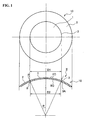
- FIG. 1 and FIG. 2 are block diagrams of a composite contact lens according to a first embodiment.
- This composite contact lens 10 is the composite contact lens having a central part consisting of a hard material and a peripheral part consisting of a soft material with hydrous property.
- a joint surface 3A between a central hard part 1 and a peripheral soft part 2 is formed of a single conical surface inclined so that a diameter D1 of the hard part 1 in the lens convex surface FC is larger than a diameter D2 of the hard part 1 in the lens concave surface BC, and an inclination angle ⁇ of the conical surface is set so that an angle ⁇ formed by the joint surface 3A and the lens concave surface BC is approximately at 90°.
- the angle ⁇ formed by the joint surface 3A and the lens concave surface BC, the angle ⁇ formed by the joint surface 3A and the lens concave surface BC is set in a range from 70° to 110°, thus making it possible to expect an increase of a strength.
- the inclination angle ⁇ of the conical surface is smaller, the effect of reducing the breakage at the joint part 3 of the composite contact lens manufactured from the lens material becomes smaller.
- the inclination angle ⁇ is larger, variation of the diameter of the central part due to a processing error of a position, where the lens is cut out, is easily made larger.
- the joint surface may be deliberately roughened to increase the joint area.
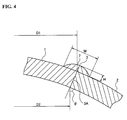
- FIG.3 and FIG.4 are block diagrams of the composite contact lens according to a second embodiment.
- This composite contact lens 10B has the central part consisting of the hard material and the peripheral part consisting of the soft material with hydrous property.
- the joint surface 3A between the central hard part 1 and the peripheral soft part 2 is formed of a single conical surface inclined so that the diameter D1 of the hard part 1 in the lens convex surface FC (front curve) is larger than the diameter D2 of the hard part 1 in the lens concave surface BC (base curve), and the inclination angle ⁇ of the conical surface is set so that the angle ⁇ formed by the joint surface 3A and the lens concave surface BC is approximately at 90°, and further an annular convex part 7 is formed, so as to project forward with respect to the convex surface curve of the optical part in an appearance of concentric with respect to an optical axis L of the lens.
- the annular convex part 7 is disposed on the joint part 3 between the central hard part 1 and the peripheral soft part 2, and a height H of the annular convex part 7 is set to be 0.1mm or less with respect to the convex surface curve of the lens of the optical part.
- a width W of the contact point of the curve forming the contour of the sectional face of the convex part 7 and the convex surface curve of the lens is set to be 0.04mm or more. This convex part 7 can be processed together with the cutting process of the lens.
- the annular convex part 7 is provided on the lens convex surface FC side, the movement can be forcibly applied to the lens by a blink.
- the annular convex part 7 is particularly arranged on the joint part 3 between the central hard part 1 and the peripheral soft part 2. Therefore, without making the entire body of the lens larger, the joint area can be increased, and the breakage at the joint part 3 can be further reduced.
- the height H of the convex part 7 is set to be 0.1 mm or less with respect to the convex surface curve of the optical part, but a foreign substance feel on wearing is developed, as the height of the convex part 7 is increased, and when the height of the convex part 7 is insufficient, an advantage of maintaining a continual movement of the lens during wearing is reduced. Accordingly, the height H of the convex part 7 is preferably set to about 0.01 to 0.05 mm with respect to the convex surface curve of the optical part.
- the circular curve forming the convex part 7 and the curve of the lens convex surface FC can be connected to each other by a smoothing curve, spline curve, and the curve using them together.
- a publicly-known lens design can be used in the aforementioned composite contact lenses 10 and 10B.
- a step due to the peripheral part swollen by hydration is generated in the vicinity of the joint part 3, and this frequently affects the movement of the lens. Therefore, a bevel may be provided at the joint part 3 on the lens convex surface BC side.
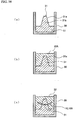
- FIG.5 shows the first embodiment of the method of manufacturing the composite contact lens.
- a taper hole 40 is formed, with a conical surface set as a hole wall surface 40a, in a material 32 for forming the soft part whereby a peripheral soft part 2 of the composite contact lenses 10 and 10B is formed (a method of forming the taper hole 40 will be described later).
- a raw material monomer mixed solution 31A of the material for forming the hard material whereby a central hard part 1 of the composite contact lenses 10 and 10B is formed is injected and polymerized in the taper hole 40.
- the lens material for the composite contact lens having the central part consisting of a hard material 31 and the peripheral part consisting of a soft material 32 can be obtained.
- the monomer having a good affinity with the peripheral soft material 32 out of the kinds of the monomers providing the central hard material 31 is permeated and polymerized into the peripheral soft material 32, and connection of the peripheral soft material 32 and the central hard material 31 is realized.
- a designation mark 30 indicates a polymerization container used for polymerizing the material 32 for forming the soft part.
- the lens is manufactured by a cutting process at a position becoming a desired central hard part diameter.
- a method of cutting process usually performed by persons skilled in the art is adopted, and in some cases, by cooling and cutting the lens material, a desired contact lens shape can be realized.
- a direction for processing the lens from the lens material is important, and a joint surface 33A between the central part material 31 and the peripheral part material 32 is formed of a single conical surface inclined so that the diameter of the central hard part 1 in the lens convex surface FC is larger than the diameter of the central hard part 1 in the lens concave surface BC (see FIG.1 and FIG.3).
- the composite contact lenses 10 and 10B manufactured by machining may be provided with hydrophilicity on the surface, so as to be adapted to a tear liquid, by a surface treatment such as a plasma treatment by inactive gas, oxygen, and air, etc, as needed, and plasma polymerization.
- the peripheral part is made to contain water, and thus a targeted composite contact lens having the peripheral part consisting of the soft material and the central part consisting of a relatively hard material can be obtained.
- the raw material monomer mixed solution 32A of the material for forming the soft part is injected and polymerized into the polymerization container 30, and the taper hole 40 is formed by a cutting process on the soft material 32 after polymerization.
- the raw material monomer mixed solution 32A of the material for forming the soft part is injected into the polymerization container 30, and a male mold 41 having a taper projection 42, with the conical face as an outer peripheral face 42a, is arranged in the raw material monomer mixed solution 32A, and in this state, by polymerizing the raw material monomer mixed solution 32A, and removing the male mold 41 after polymerization, the soft material 32 having the taper hole 40 is obtained.
- the male mold 41 is integrally formed with the inner face of a lid 43 for sealing an upper opening part of the polymerization container 30.
- the raw material monomer mixed solution 32A of the material for forming the soft part is injected into the polymerization container 30, and a male mold 48 having a projection 47 for forming the pilot hole is disposed in the raw material monomer mixed solution 32A, and in this state, by polymerizing the raw material monomer mixed solution 32A and removing the male mold 48 after polymerization, the soft material 32 having a pilot hole 49 is formed, then by using this pilot hole 48, the taper hole 40 is formed on the soft material 32 by a cutting process.
- the male mold 48 is integrally formed with the inner face of a lid 46 for sealing the upper opening part of the polymerization container 30.
- the inner face of the polymerization container 30 is constituted as the molding face having high adhesiveness capable of firmly adhering to the soft material 32 after polymerization.
- the surface treatment, etc, for improving adhesiveness is applied.
- the surfaces of the male molds 41 and 48 are constituted as the molding face having low adhesiveness capable of hardly adhering to the soft material 32 after polymerization.
- lids 43 and 46 integrally having the male molds 41 and 48 are manufactured by a polyolefin resin, etc, not adhered to the soft material 32 after polymerization.
- the peripheral soft material 32 is adhered to the polymerization container 30 side and is not adhered to the projections 42 and 47. This alleviates the internal stress generated by the shrinkage due to polymerization. Therefore, even if the central part monomer mixed solution 31A is injected later, an advantage that the columnar part is not deformed, can be obtained.
- the polymerization container 30 is enough to be a form suitable for a succeeding mechanical cutting process, and for example, in order to provide a grip part of a cutting machine, it is preferable to provide a concave/convex part on the side face and a bottom face of the polymerization container, and provide a concave/convex curvature.
- the soft material 32 is previously polymerized, and the raw material monomer mixed solution 31A of the hard material is injected and polymerized in the taper hole 40 formed on the soft material 32 later.
- the hard material 31 is previously formed, and the soft materials 32 is polymerized in the circumference thereof later.
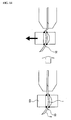
- FIG.9 and FIG. 10 show such a method of manufacturing the lens material.
- the hard material 31 having a taper projection 31b, with the conical face as an outer peripheral face 31a is prepared as the material for forming the hard part whereby the central hard part 1 of the composite contact lenses 10 and 10B is formed, and in the circumference of this taper projection 31b, the raw material monomer mixed solution 32A for the material for the soft part, whereby the peripheral soft part 2 of the composite contact lenses 10 and 10B is constituted, is polymerized and made integral with the hard material 31.
- the composite contact lens having the central part consisting of the hard material and the peripheral part consisting of the soft material can be obtained.
- the taper projection 31b made of the hard material 31 is set inside the polymerization container 30, and the monomer mixed solution 32A for providing the peripheral soft material is polymerized in the circumference of this taper projection 31b by an appropriate method.
- the monomer having a good affinity with the peripheral soft material out of the kinds of the monomers providing the peripheral part material is permeated and polymerized into the central part material, and connection of the central part material and the peripheral part material is realized.
- FIG. 9 shows a case that the taper projection 31b is integrally formed with a lid 51 for sealing the upper opening part of the polymerization container 30, and if the upper opening part of the polymerization container 30 is closed by the lid 51, the taper projection 31b made of the hard material can be set at a predetermined position.
- FIG.10 shows a case that the male mold having the taper projection 31b is set in an inner bottom part of the polymerization container 30.
- the copolymer of poly-2-hydroxyethyl methacrylate and a publicly-known soft contact lens material, etc, are used in the peripheral part material of the composite material.
- a soft material with low moisture content is preferable after swollen by hydration.
- poly-methyl-methacrylte and a publicly-known hard contact lens material having oxygen permeability are used in the central part material.
- FIG.11 to FIG. 13 show a relation between an angle (taper angle) ⁇ of the conical face and an angle ⁇ formed by the joint surface 3A and the lens concave surface BC, in accordance with a difference of the concave surface BC (6mm, 8mm, and 10mm), when a diameter of the central hard part 1 is set at 8.00mm.
- Table 1 shows this relation by numerical values. From these figure and table, the taper hole 40 for setting the angle ⁇ at approximately 90° and the inclination angle ⁇ of the taper projection 31b can be known.
- 2,2'-azobisisobutyro nitrile is added to the monomer mixed solution by 0.1wt% of monomer mixed solution comprising 44wt% of 2-hydroxyethyl methacrylate, 35wt% of 2-methoxyethyl acrylate, 20wt% of methyl methacrylate, and 1wt% of ethylene glycol dimethacrylate, which is then stirred to dissolve.
- the mixed solution thus obtained is injected into a cylindrical polymerization container made of polypropylene with inner diameter of 17 mm, that has undergone plasma treatment under a condition of output: 50W, a degree of vacuum: 0.6 Torr, a reactive gas: and Ar, processing time: 120 seconds, by using "PA-100AT” produced by KYOTO ELECTRONICS MANUFACTURING CO. ,LTD, then after sealing this container, the mixed solution is retained for 48 hours at 40° and 6 hours at 80° in a hot air circulating dryer, thereafter is cooled naturally up to a room temperature and a peripheral part polymer (soft material 32) is obtained.
- a peripheral part polymer soft material 32
- the mixed solution obtained by adding 40wt% of tris(trimethylsiloxy)- ⁇ -methacryloxypropylsilan, 45wt% of 2,2,2-trifluoroethyl methacrylate, 10wt% of 2-hydroxyethyl methacrylate, 5wt% of ethylene glycol dimethacrylate, and 0.2wt% of 2,2'- azobisisobutyro nitrile to dissolve therein and the lid is sealed, which is then put in the hot air circulating dryer again, and under the same condition as described above, the monomer mixture in the cavity is polymerized, to obtain the composite material (lens material).
- the composite material is not taken out of the polymerization container, and by making a cutting machine grip this polymerization container, the composite material is machined by mechanically cutting by a normal machining technique, so as to obtain a lens with a thickness of 0.15 mm at a position where the central hard part diameter is 8 mm in a direction that the concave surface of the lens to be manufactured becomes the bottom surface side of the composite material. Thereafter, this lens is dipped in the normal saline, and it is found that the lens after sufficiently dipped in the normal saline is the composite contact lens having the central part consisting of the hard material and the peripheral part consisting of the soft material.
- breaking strength of the joint part of this composite contact lens, with the peripheral part swollen by hydration is evaluated by the following method using a universal testing machine "MINI44" by INSTRON Corporation. Namely, after clamping and fixing the central hard part 1 with a jig at slightly inside of the joint part, the peripheral soft part 2 is gripped and pulled in the shear direction toward the convex surface of the lens at a speed of 6 mm/min.
- the breaking load generated here is evaluated as a comparison of a value of a comparative example 1. Parts where the breakage occurs and ratios of generating the damage at the joint part are corresponded and a result is shown in a table 2.
- 2,2'-azobisisobutyro nitrile is added to the monomer mixed solution composed of 46wt% of 2-hydroxyethyl methacrylate, 38wt% of 2-methoxyethyl acrylate, 15wt% of 2,2,2-trifluoroethyl methacrylate, and 1wt% of ethylene glycol dimethacrylate, by 0.1wt% of the monomer mixed solution, which is then stirred to dissolve.
- the mixed solution thus obtained is injected into a cylindrical polymerization container made of polypropylene with inner diameter of 17mm, that has undergone corona discharge treatment inside thereof by a ball electrode, with tip end set at 6mm, under a condition of set voltage: 24kV, set output: 51W, processing time: 5 seconds, under atmospheric air, by using "HV-2010" produced by TANTEC Corporation, then after sealing this container, the mixed solution is retained for 42 hours at 42° and 6 hours at 80° in the hot air circulating dryer, thereafter is cooled naturally up to a room temperature and the peripheral part polymer is obtained.
- a columnar cavity (taper hole 40) having the inclination, with the tip made gradually smaller, is formed by the cutting process in the center of this polymer (soft material 32). Note that the inclination of ⁇ 20° is provided to the axis of this cavity.
- the mixed solution obtained by adding 40wt% of tris(trimethylsiloxy)- ⁇ -methacryloxypropylsilan, 47wt% of 2,2,2-trifluoroethyl methacrylate, 8wt% of 2-hydroxyethyl methacrylate, 5wt% of ethylene glycol dimethacrylate, and 0.2wt% of 2,2'- azobisisobutyro nitrile to dissolve therein and the lid is sealed, which is then put in the hot air circulating dryer again, and under the same condition as described above, the monomer mixture in the cavity is polymerized, to obtain the composite material (lens material).
- the composite material is not taken out of the polymerization container, and by making a cutting machine grip this polymerization container, the composite material is machined by mechanically cutting by a normal machining technique, so as to obtain the lens with a thickness of 0.15 mm at the position where the central hard part diameter is 8 mm in the direction that the concave surface of the lens to be manufactured becomes the bottom surface side of the composite material. Thereafter, this lens is dipped in the normal saline, and it is found that the lens after sufficiently dipped in the normal saline is the composite contact lens having the central part consisting of the hard material and the peripheral part consisting of the soft material. The same evaluation as the embodiment 1 is executed for the composite contact lens, with the peripheral part swollen by hydration.
- the composite contact lens is obtained in the same way as the example 1, excluding the point that the columnar cavity, that has undergone the cutting process, is not provided in the center part of the peripheral part material, and the evaluation is made in the same way as the example 1.
- the composite contact lens is obtained in the same way as the example 3, excluding the point that the inclination is not provided in the columnar cavity, that has undergone the cutting process, in the center part of the peripheral part material, and the evaluation is made in the same way as the example 1.
- a concentric convex part 7 having the following shape is formed on the lens convex surface FC side of the joint part between the central hard material 1 and the peripheral soft material 2.
- the movement on the eyeball is confirmed by a slit lamp "SL-7F" by TOPCON Corporation after 1 hour when the lens is worn.
- the evaluation is shown by o: good, ⁇ : slightly bad, x: bad.
- the concentric convex part having the following shape is formed on the convex surface side of the joint part between central hard material and the peripheral soft material.
- Height H of the convex part 7 with respect to the convex surface curve of the optical part 0.04mm
- Width W of the contact point of the curve forming the convex part 7 and the convex surface curve of the lens 0.64mm
- the same concentric convex part as that of the example 5 is formed on the convex surface side of the joint part between the central hard material and the peripheral soft material.
- the movement on the eyeball and the wearing feel are evaluated in the same way as the example 5.
- the movement on the eyeball and the wearing feel of the lens of the example 1 not having the convex part on the convex surface side of the lens are evaluated in the same way as the example 5.
- the concentric convex part having the following shape is formed on the convex surface side of the joint part between the central hard material and the peripheral soft material.
- table 2 shows the inclination angle of the joint surface, the breaking load of the joint part, breaking part, and breaking ratio of the joint part (%).
- the breaking strength of the joint part between the central hard part and the peripheral soft part is intentionally improved compared to the comparative example, and the damage at the joint part of the composite contact lens having the central part consisting of the hard material and the peripheral part consisting of a hydrous soft material is significantly reduced.
- center material central hard material
- peripheral soft material referred to as "peripheral material” hereafter
- cross-linking agent between the centeral material and the peripheral material, the initiator of the centeral material and the peripheral material, and a colorant of the centeral material and the peripheral material
- the silicon-containing alkyl (metha) acrylate of the hard material is used for improving the oxygen permeability of the centeral material, and examples thereof include trimethylsiloxydimethylsilylpropyl(metha)acrylate, bis(trimethylsiloxy)methylsilylpropyl(metha)acrylate, tris(trimethylsiloxy)silylpropyl(metha)acrylate, bis[bis(trimethylsiloxy)methylsiloxanyl]trimethylsiloxysily lpropyl(metha)acrylate, bis(trimethylsiloxy)methylsiloxanylmonopentamethyldi-silox anylmonotrimethylsiloxanylpropyl(metha)acrylate, bis(pentamethyldi-siloxanyl)bis(trimethylsyloxy)methylsilo xanylsilylpropyl(metha)acrylate, etc.
- Its use amount is preferably in a range of 30 to 60wt%. This is because if the use amount is 30wt% or less, a desired oxygen permeability can not be obtained, and if the use amount is beyond 60wt%, hardness is insufficient, and the centeral material is likely to become fragile. It is particularly preferably set at 35 to 50wt%.
- fluorine-contained alkyl (metha) acrylate is used for improving the oxygen permeability of the centeral material and for applying hardness, and examples thereof include 2,2,2-trifluoroethyl methacrylate, 2,2,2-trifluoroethyl acrylate, 2,2,3,3- tetrafluoropropyl methacrylate, 2,2,3,3-tetrafluoropropyl acrylate, 2,2,3,3,3-pentafluoropropylmethacrylate, 2,2,3,3,3-pentafluoropropylacrylate, 2,2,2-trifluoro-1-trifluoromethylethylmetacrylate, 2,2,2-trifluoro-1-trifluoromethylethylacrylate, 2,2,3,3-tetrafluorofluorotertiaryamylmethacrylate, 2,2,3,3-tetrafluorotertiaryamylacrylate, 2,2,3,4,4,4-hexafluorobut
- Its use amount is preferably in a range of 30 to 60wt%. If the use amount is under 30wt%, desired oxygen permeability and hardness can not be obtained, and regarding the oxygen permeability, the silicon-containing alkyl (metha) acrylate is dominant. Therefore, when the use amount is beyond 60wt%, by decrease of an addition ratio of the silicon-containing alkyl (metha) acrylate, the oxygen permeability is decreased. It is particularly preferably set in a range of 40 to 55wt%.
- 2-hydroxyethyl methacrylate has hydrophilic properties, thus giving the hydrophilic properties (wetting properties) to the polymer of silicon-containing alkyl (metha)acrylate and fluorine-contained alkyl (metha) acrylate having hydrophobic properties, and improving affinity and adhesiveness with the peripheral material.
- Its use amount is preferably in a range of 2 to 15wt%. If it is under 2wt%, desired wetting properties, adhesiveness, and affinity can not be obtained, and depending on a degree of swelling by hydration of the hydrous peripheral material, the breakage occurs to the joint part due to a difference of the degree of swelling between the central material and the peripheral material, and the peripheral part becomes in an appearance of a wall, thus making it impossible to form a lens shape.
- the hydrous 2-hydroxyethyl methacrylate of the peripheral material has been used for long years as a raw material component of the hydrous soft contact lens, and shows a result of safety. It has hydrophilic properties, and has both of the advantage of swelling and softening by hydration and the advantage of hardening the polymer, and is used in a range of 20 to 60wt%. If the use amount is under 20wt%, the advantage of swelling and softening by hydration can not be sufficiently obtained, and if it is beyond 60wt%, water content after hydration is increased, thus making it difficult to accurately reflect a machining shape on the lens after hydration. For the reason thus described, the use amount is particularly preferably set in a range of 30 to 50wt%.
- 2-methoxyethyl acrylate gives flexibility to the lens after hydration and has an advantage of hydrophilic properties and suppressing an adhesion of stain components in the tear liquid, and is used in a range of 20 to 60wt%. If the use amount is under 20wt%, a sufficient flexibility after hydration can not be obtained, thereby damaging the wearing feel when the contact lens is used, and if the use amount is beyond 60wt%, the polymer becomes excessively soft, thus making it difficult to be cut. For the reason thus described, the use amount is particularly preferably set in a range of 30 to 50wt%.
- Fluorine-contained alkyl (metha) acrylate has an advantage of suppressing the water content after hydration and swelling, and contributes to an adhesion resistance to a lipid, improvement of the oxygen permeability of the peripheral material, the hydrophilic properties with the centeral material, and the adhesiveness, and examples thereof include 2,2,2-trifluoroethyl methacrylate, 2,2,2-trifluoroethyl acrylate, 2,2,3,3- tetrafluoropropyl methacrylate, 2,2,3,3-tetrafluoropropyl acrylate, 2,2,3,3,3-pentafluoropropylmethacrylate, 2,2,3,3,3-pentafluoropropylacrylate, 2,2,2-trifluoro-1-trifluoromethylethylmetacrylate, 2,2,2-trifluoro-1-trifluoromethylethylacrylate, 2,2,3,3-tetrafluorofluorotertiaryamylmethacrylate
- Its use amount is preferably in a range of 5 to 30wt%. If it is under 5wt%, the water absorption is excessively increased, and desired hydrophobic properties with the centeral material and adhesiveness can not be obtained. If it becomes beyond 30wt%, the water content after hydration and swelling is decreased, thus deteriorating flexibility. In addition, in this case, water repellency becomes high, and the surface of the lens is easily dried, thus becoming easy to dim.
- the use amount is particularly preferably in a range of 10 to 20wt%.
- a cross-linking monomer such as ethylene glycol dimethacrylate, diethylene glycol methacrylate, triethylene glycol dimethacrylate, allyl methacrylate, diallyl methacrylate, diallyl maleate, diallyl isophthalate, and triallyl isocyanurate can be used if desired, in addition to the above-described three components of the central and peripheral materials, to give mechanical strength and durability.
- the content of the cross-linking monomer relates to physical properties of each material, and when the content of such a cross-linking monomer is excessively increased, the mechanical strength of the central material is apt to deteriorate, the water content of the peripheral material is apt to decrease, and the flexibility is also apt to decrease.
- the content of the cross-linking monomer is preferably set at 15wt% or less in the central material, and 5wt% or less in the peripheral material, out of a total amount of a copolymer composition, in consideration of a deformation or the breakage of the lens due to the difference of the degree of swelling, the hydrophilic properties, and the adhesiveness.
- a polymerization initiator is added to the mixed solution containing the aforementioned monomer, which is then sufficiently stirred to obtain a homogeneous monomer mixed solution, and the polymerization is performed from the central material to the peripheral material, or in its reversed order.
- the polymerization initiator used at this time includes, for example, peroxide such as lauroyl peroxide, cumene hydroperoxide, benzoyl peroxide, 2,2'-azobis(2,4-dimethylvaleronitrile), and 2,2'-azobisisobutylonitrile when thermal polymerization is employed, and a optical initiator such as benzoin methyl ether, 1-hydroxycyclohexyl phenyl ketone, 2,2-dimethoxy-2-phenylacetophenone, 2-hydroxy-1-phenylpropane-1-on, 2,4,6-trimethylbenzoyldiphenylphosphine oxide, phenylbis(2,4,5-trimethylbenzoyl)-phosphine oxide are used when an photo-polymerization method is employed.
- peroxide such as lauroyl peroxide, cumene hydroperoxide, benzoyl peroxide, 2,2'-azobis(2,4-dimethylvaleronitrile), and 2,2
- a polymerizable ultraviolet absorbent and a polymerizable pigment having excellent elution resistance and toughness can be used, and can be selected and used for each material.
- 5-chloro-2-[2-hydroxy-5-( ⁇ -methacryloyloxyethylcarbamoylox yethyl)]phenyl-2H-benzotriazole, 2-(2'hydroxy-3'-tributyl-5'-methylphenyl)-5-(2'methacryl-oyloxyethyl)benzotria zol are given as examples of the polymerizable ultraviolet ray absorbent.
- 1,4-bis(4- vinylbenzilamino) anthraquinone, 1-p-hydroxybenzylamino-4-pvinylbenzylamino anthraquinone, 1-anilino-4-methacryloylanthraquinone, etc, are given as examples of the polymerizable pigment.
- the hydrous peripheral part of the present invention is colored, there is no problem in using a chemical dyeing method in which without using the aforementioned pigments, the hydrous peripheral part is dipped into a chemical dyeing bath by using a dye such as a Vat Blue 6 to sufficiently dip a leuco body of the dye in an overall body of the lens, and thereafter the leuco body is dipped into an oxidizing bath, is changed into a oxidized body, an is fixed.
- a phthalocyanine-based pigment such as an Alcian Blue 8GX, an Alcian Green 2GX, and a Pigment Blue 6 can be used as an Alcian Blue 8GX, an Alcian Green 2GX, and a Pigment Blue 6 can be used.
- use amounts of the aforementioned polymerizable ultraviolet ray absorbent and the polymerizable pigment depend on a thickness of a lens, usually, they are set at 5wt% or less or preferably 3wt% or less of the copolymer component. When the use amount exceeds 5wt%, a mechanical strength of the obtained contact lens is sometimes deteriorated, and when toxicity of the ultraviolet ray absorbent and the pigment is taken into consideration, this contact lens is likely to be not suitable as a contact lens that directly comes in contact with a living body.
- the central material As the central material, the peripheral material, and the cross-linking material, typical examples are used such as:
- the contact lens manufactured by changing a composition ratio is evaluated by the following items,
Landscapes
- Health & Medical Sciences (AREA)
- Ophthalmology & Optometry (AREA)
- Physics & Mathematics (AREA)
- General Physics & Mathematics (AREA)
- Optics & Photonics (AREA)
- Engineering & Computer Science (AREA)
- General Health & Medical Sciences (AREA)
- Manufacturing & Machinery (AREA)
- Mechanical Engineering (AREA)
- Eyeglasses (AREA)
- Casting Or Compression Moulding Of Plastics Or The Like (AREA)
Applications Claiming Priority (2)
| Application Number | Priority Date | Filing Date | Title |
|---|---|---|---|
| JP2004377017A JP4614271B2 (ja) | 2004-12-27 | 2004-12-27 | 複合コンタクトレンズ及びレンズ素材の製造方法 |
| PCT/JP2005/022923 WO2006070599A1 (ja) | 2004-12-27 | 2005-12-14 | 複合コンタクトレンズ及びレンズ素材の製造方法 |
Publications (4)
| Publication Number | Publication Date |
|---|---|
| EP1832913A1 true EP1832913A1 (de) | 2007-09-12 |
| EP1832913A8 EP1832913A8 (de) | 2008-01-02 |
| EP1832913A4 EP1832913A4 (de) | 2009-03-11 |
| EP1832913B1 EP1832913B1 (de) | 2011-11-23 |
Family
ID=36614719
Family Applications (1)
| Application Number | Title | Priority Date | Filing Date |
|---|---|---|---|
| EP05816814A Expired - Lifetime EP1832913B1 (de) | 2004-12-27 | 2005-12-14 | Zusammengesetzte kontaktlinse und deren herstellungsverfahren |
Country Status (6)
| Country | Link |
|---|---|
| EP (1) | EP1832913B1 (de) |
| JP (1) | JP4614271B2 (de) |
| KR (1) | KR101250597B1 (de) |
| CN (1) | CN101076752B (de) |
| ES (1) | ES2381836T3 (de) |
| WO (1) | WO2006070599A1 (de) |
Cited By (4)
| Publication number | Priority date | Publication date | Assignee | Title |
|---|---|---|---|---|
| WO2013024213A1 (fr) * | 2011-08-16 | 2013-02-21 | Lentilles | Procede, dispositif et piece composite pour la fabrication d'une lentille hybride |
| EP2855132A4 (de) * | 2012-05-25 | 2015-05-20 | Crt Technology Inc | Optische mehrkomponentenvorrichtung mit raum |
| US10049275B2 (en) | 2012-05-25 | 2018-08-14 | Paragon Crt Company Llc | Multicomponent optical device for visual and audible translation and recognition |
| US10712588B2 (en) | 2012-05-25 | 2020-07-14 | Paragon Crt Company Llc | Contact lens having a space |
Families Citing this family (12)
| Publication number | Priority date | Publication date | Assignee | Title |
|---|---|---|---|---|
| FR2956752B1 (fr) * | 2010-02-25 | 2012-07-27 | Lentilles | Procede de fabrication d'une lentille de contact hybride |
| CN102411219A (zh) * | 2011-10-31 | 2012-04-11 | 甘肃康视达眼镜有限公司 | 一种软镜和硬镜组合的隐形眼镜及其制造方法 |
| US20130258276A1 (en) * | 2012-03-27 | 2013-10-03 | Jonathan Hansen | Increased stiffness center optic in soft contact lenses for astigmatism correction |
| US10209534B2 (en) | 2012-03-27 | 2019-02-19 | Johnson & Johnson Vision Care, Inc. | Increased stiffness center optic in soft contact lenses for astigmatism correction |
| CN103345075B (zh) * | 2013-06-26 | 2014-10-22 | 无锡市康明医疗器械有限公司 | 一种绑带式软性角膜接触镜 |
| CN103721290B (zh) * | 2013-12-18 | 2016-08-17 | 欧普康视科技股份有限公司 | 一种接触镜消毒湿润系统及消毒湿润方法 |
| JP2019518999A (ja) * | 2016-06-07 | 2019-07-04 | フェイ‐チュアン チェン | 眼用レンズ、および、その製造方法 |
| US11125916B2 (en) | 2016-07-06 | 2021-09-21 | Johnson & Johnson Vision Care, Inc. | Silicone hydrogels comprising N-alkyl methacrylamides and contact lenses made thereof |
| EP3625620B1 (de) | 2017-05-08 | 2025-09-10 | SIGHTGLASS VISION, Inc. | Herstellungsverfahren von kontaktlinsen zur reduzierung von myopie |
| US20190064543A1 (en) * | 2017-08-30 | 2019-02-28 | Johnson & Johnson Vision Care, Inc. | Atoric Surfaces to Minimize Secondary Astigmatism in Contact Lenses for the Correction of Astigmatism |
| WO2020013009A1 (ja) * | 2018-07-13 | 2020-01-16 | Agc株式会社 | 含フッ素重合体、膜及び医療用具 |
| JPWO2023176479A1 (de) * | 2022-03-15 | 2023-09-21 |
Family Cites Families (11)
| Publication number | Priority date | Publication date | Assignee | Title |
|---|---|---|---|---|
| DE2309933C2 (de) * | 1973-02-28 | 1983-02-24 | Söhnges Optik Wilhelm P. Söhnges, 8000 München | Mikrokontaktlinse mit einem optischen harten lInsenkern und einem flexiblen Ringteil |
| US4208362A (en) * | 1975-04-21 | 1980-06-17 | Bausch & Lomb Incorporated | Shaped body of at least two polymerized materials and method to make same |
| JPS5332266A (en) * | 1976-09-06 | 1978-03-27 | Itsuki Ban | Apparatus for rotating eccentric wheel by drive shaft |
| US4701288A (en) * | 1985-06-05 | 1987-10-20 | Bausch & Lomb Incorporated | Method of making articles of dissimilar polymer compositions |
| EP0362137A3 (de) * | 1988-09-28 | 1991-09-04 | Ciba-Geigy Ag | Geformte Polymere mit hydrophilen Oberflächen und ein Verfahren zu deren Herstellung |
| US5010155A (en) * | 1988-09-28 | 1991-04-23 | Ciba-Geigy Corporation | Vinyl-urethane substituted hydroxyethyl cellulose |
| US5115056A (en) * | 1989-06-20 | 1992-05-19 | Ciba-Geigy Corporation | Fluorine and/or silicone containing poly(alkylene-oxide)-block copolymers and contact lenses thereof |
| US5160463A (en) * | 1990-10-30 | 1992-11-03 | Pilkington Visioncare, Inc. | Method of manufacturing a contact lens |
| US5433898A (en) * | 1992-09-11 | 1995-07-18 | Pilkington Barnes Hind, Inc. | Method of manufacturing a contact lens |
| JP2003228029A (ja) * | 2002-02-05 | 2003-08-15 | Hoya Healthcare Corp | 含水性ソフトコンタクトレンズ材料 |
| US7104648B2 (en) * | 2002-09-06 | 2006-09-12 | Synergeyes, Inc. | Hybrid contact lens system and method |
-
2004
- 2004-12-27 JP JP2004377017A patent/JP4614271B2/ja not_active Expired - Fee Related
-
2005
- 2005-12-14 WO PCT/JP2005/022923 patent/WO2006070599A1/ja not_active Ceased
- 2005-12-14 EP EP05816814A patent/EP1832913B1/de not_active Expired - Lifetime
- 2005-12-14 ES ES05816814T patent/ES2381836T3/es not_active Expired - Lifetime
- 2005-12-14 CN CN2005800323596A patent/CN101076752B/zh not_active Expired - Fee Related
- 2005-12-14 KR KR1020077005302A patent/KR101250597B1/ko not_active Expired - Fee Related
Cited By (7)
| Publication number | Priority date | Publication date | Assignee | Title |
|---|---|---|---|---|
| WO2013024213A1 (fr) * | 2011-08-16 | 2013-02-21 | Lentilles | Procede, dispositif et piece composite pour la fabrication d'une lentille hybride |
| FR2979072A1 (fr) * | 2011-08-16 | 2013-02-22 | Lentilles | Procede, dispositif et piece composite pour la fabrication d'une lentille hybride |
| US9539761B2 (en) | 2011-08-16 | 2017-01-10 | Lentilles | Process, device and composite part for manufacturing a hybrid lens |
| EP2855132A4 (de) * | 2012-05-25 | 2015-05-20 | Crt Technology Inc | Optische mehrkomponentenvorrichtung mit raum |
| US9442307B2 (en) | 2012-05-25 | 2016-09-13 | Crt Technology, Inc. | Multicomponent optical device having a space |
| US10049275B2 (en) | 2012-05-25 | 2018-08-14 | Paragon Crt Company Llc | Multicomponent optical device for visual and audible translation and recognition |
| US10712588B2 (en) | 2012-05-25 | 2020-07-14 | Paragon Crt Company Llc | Contact lens having a space |
Also Published As
| Publication number | Publication date |
|---|---|
| KR20070100869A (ko) | 2007-10-12 |
| CN101076752B (zh) | 2012-02-29 |
| ES2381836T3 (es) | 2012-06-01 |
| EP1832913B1 (de) | 2011-11-23 |
| CN101076752A (zh) | 2007-11-21 |
| JP4614271B2 (ja) | 2011-01-19 |
| EP1832913A4 (de) | 2009-03-11 |
| WO2006070599A1 (ja) | 2006-07-06 |
| JP2006184477A (ja) | 2006-07-13 |
| KR101250597B1 (ko) | 2013-04-03 |
| EP1832913A8 (de) | 2008-01-02 |
Similar Documents
| Publication | Publication Date | Title |
|---|---|---|
| EP1832913B1 (de) | Zusammengesetzte kontaktlinse und deren herstellungsverfahren | |
| US4121885A (en) | Method to produce a composite contact lens | |
| US4093361A (en) | Composite prosthetic polymeric devices | |
| CA1132299A (en) | Contact lenses of high gas permeability | |
| EP0814956B2 (de) | Herstellung optischer elemente | |
| EP1589367B1 (de) | Photochromische kontaktlinse mitausgezeichneten entfärbungseigenschaften | |
| AU717778B2 (en) | Soft contact lens with moisture content and method for producing the same | |
| WO1996034735A1 (en) | Adhesive photochromic matrix layers for use in optical articles | |
| EP1337395B1 (de) | Photochromische artikel und verfahren zu ihrer herstellung | |
| AU2002245037A1 (en) | Photochromic articles and methods for making them | |
| JP5621118B2 (ja) | 着色コンタクトレンズおよびその製造方法 | |
| US20040131872A1 (en) | Photochromic articles and methods for making them | |
| AU642963B2 (en) | Ophthalmic lenses based on amorphous fluoropolymers | |
| JP2014134709A (ja) | 多層コンタクトレンズおよびその製造方法 | |
| KR100210348B1 (ko) | 소프트 콘택트렌즈 | |
| JP2003228029A (ja) | 含水性ソフトコンタクトレンズ材料 | |
| KR102245626B1 (ko) | 염료용출 방지 콘택트렌즈의 제조방법 및 이에 의해 제조된 콘택트렌즈 | |
| KR102186832B1 (ko) | 표면조도에 의한 착용감 개선 콘택트 렌즈의 제조방법 | |
| CA1214899A (en) | Soft contact lens | |
| JPH06296629A (ja) | 眼内レンズの製造方法 | |
| JPS6339046B2 (de) | ||
| JPH0956804A (ja) | 眼内レンズおよびその製造方法 | |
| JPS60185924A (ja) | 含水ソフトコンタクトレンズ | |
| JPH10104554A (ja) | 高含水ソフトコンタクトレンズおよびその製造方法 | |
| JPH0249609B2 (de) |
Legal Events
| Date | Code | Title | Description |
|---|---|---|---|
| PUAI | Public reference made under article 153(3) epc to a published international application that has entered the european phase |
Free format text: ORIGINAL CODE: 0009012 |
|
| 17P | Request for examination filed |
Effective date: 20070504 |
|
| AK | Designated contracting states |
Kind code of ref document: A1 Designated state(s): DE ES FR GB IT |
|
| RAP1 | Party data changed (applicant data changed or rights of an application transferred) |
Owner name: HOYA HEALTHCARE CORPORATION |
|
| DAX | Request for extension of the european patent (deleted) | ||
| RBV | Designated contracting states (corrected) |
Designated state(s): DE ES FR GB IT |
|
| A4 | Supplementary search report drawn up and despatched |
Effective date: 20090206 |
|
| 17Q | First examination report despatched |
Effective date: 20090525 |
|
| RAP1 | Party data changed (applicant data changed or rights of an application transferred) |
Owner name: HOYA CORPORATION |
|
| GRAP | Despatch of communication of intention to grant a patent |
Free format text: ORIGINAL CODE: EPIDOSNIGR1 |
|
| RTI1 | Title (correction) |
Free format text: COMPOSITE CONTACT LENS AND PRODUCTION METHOD FOR SUCH A LENS |
|
| GRAS | Grant fee paid |
Free format text: ORIGINAL CODE: EPIDOSNIGR3 |
|
| GRAA | (expected) grant |
Free format text: ORIGINAL CODE: 0009210 |
|
| AK | Designated contracting states |
Kind code of ref document: B1 Designated state(s): DE ES FR GB IT |
|
| REG | Reference to a national code |
Ref country code: GB Ref legal event code: FG4D |
|
| REG | Reference to a national code |
Ref country code: DE Ref legal event code: R096 Ref document number: 602005031408 Country of ref document: DE Effective date: 20120119 |
|
| REG | Reference to a national code |
Ref country code: ES Ref legal event code: FG2A Ref document number: 2381836 Country of ref document: ES Kind code of ref document: T3 Effective date: 20120601 |
|
| PLBE | No opposition filed within time limit |
Free format text: ORIGINAL CODE: 0009261 |
|
| STAA | Information on the status of an ep patent application or granted ep patent |
Free format text: STATUS: NO OPPOSITION FILED WITHIN TIME LIMIT |
|
| 26N | No opposition filed |
Effective date: 20120824 |
|
| REG | Reference to a national code |
Ref country code: DE Ref legal event code: R097 Ref document number: 602005031408 Country of ref document: DE Effective date: 20120824 |
|
| REG | Reference to a national code |
Ref country code: FR Ref legal event code: PLFP Year of fee payment: 11 |
|
| REG | Reference to a national code |
Ref country code: FR Ref legal event code: PLFP Year of fee payment: 12 |
|
| REG | Reference to a national code |
Ref country code: FR Ref legal event code: PLFP Year of fee payment: 13 |
|
| PGFP | Annual fee paid to national office [announced via postgrant information from national office to epo] |
Ref country code: IT Payment date: 20221111 Year of fee payment: 18 Ref country code: GB Payment date: 20221027 Year of fee payment: 18 Ref country code: FR Payment date: 20221110 Year of fee payment: 18 Ref country code: DE Payment date: 20221102 Year of fee payment: 18 |
|
| PGFP | Annual fee paid to national office [announced via postgrant information from national office to epo] |
Ref country code: ES Payment date: 20230109 Year of fee payment: 18 |
|
| P01 | Opt-out of the competence of the unified patent court (upc) registered |
Effective date: 20230418 |
|
| REG | Reference to a national code |
Ref country code: DE Ref legal event code: R119 Ref document number: 602005031408 Country of ref document: DE |
|
| GBPC | Gb: european patent ceased through non-payment of renewal fee |
Effective date: 20231214 |
|
| PG25 | Lapsed in a contracting state [announced via postgrant information from national office to epo] |
Ref country code: DE Free format text: LAPSE BECAUSE OF NON-PAYMENT OF DUE FEES Effective date: 20240702 |
|
| PG25 | Lapsed in a contracting state [announced via postgrant information from national office to epo] |
Ref country code: GB Free format text: LAPSE BECAUSE OF NON-PAYMENT OF DUE FEES Effective date: 20231214 |
|
| PG25 | Lapsed in a contracting state [announced via postgrant information from national office to epo] |
Ref country code: FR Free format text: LAPSE BECAUSE OF NON-PAYMENT OF DUE FEES Effective date: 20231231 |
|
| PG25 | Lapsed in a contracting state [announced via postgrant information from national office to epo] |
Ref country code: GB Free format text: LAPSE BECAUSE OF NON-PAYMENT OF DUE FEES Effective date: 20231214 Ref country code: FR Free format text: LAPSE BECAUSE OF NON-PAYMENT OF DUE FEES Effective date: 20231231 Ref country code: DE Free format text: LAPSE BECAUSE OF NON-PAYMENT OF DUE FEES Effective date: 20240702 |
|
| REG | Reference to a national code |
Ref country code: ES Ref legal event code: FD2A Effective date: 20250129 |
|
| PG25 | Lapsed in a contracting state [announced via postgrant information from national office to epo] |
Ref country code: ES Free format text: LAPSE BECAUSE OF NON-PAYMENT OF DUE FEES Effective date: 20231215 |
|
| PG25 | Lapsed in a contracting state [announced via postgrant information from national office to epo] |
Ref country code: IT Free format text: LAPSE BECAUSE OF NON-PAYMENT OF DUE FEES Effective date: 20231214 |