EP1833024B1 - Bildverarbeitungsvorrichtung, Bildverarbeitungsverfahren und Bildverarbeitungsprogramm - Google Patents
Bildverarbeitungsvorrichtung, Bildverarbeitungsverfahren und Bildverarbeitungsprogramm Download PDFInfo
- Publication number
- EP1833024B1 EP1833024B1 EP07250803.9A EP07250803A EP1833024B1 EP 1833024 B1 EP1833024 B1 EP 1833024B1 EP 07250803 A EP07250803 A EP 07250803A EP 1833024 B1 EP1833024 B1 EP 1833024B1
- Authority
- EP
- European Patent Office
- Prior art keywords
- data
- contours
- triangles
- stencil
- straight line
- Prior art date
- Legal status (The legal status is an assumption and is not a legal conclusion. Google has not performed a legal analysis and makes no representation as to the accuracy of the status listed.)
- Active
Links
Images






Classifications
-
- G—PHYSICS
- G06—COMPUTING OR CALCULATING; COUNTING
- G06T—IMAGE DATA PROCESSING OR GENERATION, IN GENERAL
- G06T1/00—General purpose image data processing
-
- G—PHYSICS
- G09—EDUCATION; CRYPTOGRAPHY; DISPLAY; ADVERTISING; SEALS
- G09G—ARRANGEMENTS OR CIRCUITS FOR CONTROL OF INDICATING DEVICES USING STATIC MEANS TO PRESENT VARIABLE INFORMATION
- G09G5/00—Control arrangements or circuits for visual indicators common to cathode-ray tube indicators and other visual indicators
- G09G5/22—Control arrangements or circuits for visual indicators common to cathode-ray tube indicators and other visual indicators characterised by the display of characters or indicia using display control signals derived from coded signals representing the characters or indicia, e.g. with a character-code memory
- G09G5/24—Generation of individual character patterns
- G09G5/246—Generation of individual character patterns of ideographic or arabic-like characters
-
- G—PHYSICS
- G06—COMPUTING OR CALCULATING; COUNTING
- G06T—IMAGE DATA PROCESSING OR GENERATION, IN GENERAL
- G06T1/00—General purpose image data processing
- G06T1/20—Processor architectures; Processor configuration, e.g. pipelining
-
- G—PHYSICS
- G06—COMPUTING OR CALCULATING; COUNTING
- G06T—IMAGE DATA PROCESSING OR GENERATION, IN GENERAL
- G06T11/00—Two-dimensional [2D] image generation
- G06T11/20—Drawing from basic elements
- G06T11/23—Drawing from basic elements using straight lines or curves
-
- G—PHYSICS
- G06—COMPUTING OR CALCULATING; COUNTING
- G06T—IMAGE DATA PROCESSING OR GENERATION, IN GENERAL
- G06T11/00—Two-dimensional [2D] image generation
- G06T11/40—Filling planar surfaces by adding surface attributes, e.g. adding colours or textures
-
- G—PHYSICS
- G06—COMPUTING OR CALCULATING; COUNTING
- G06T—IMAGE DATA PROCESSING OR GENERATION, IN GENERAL
- G06T3/00—Geometric image transformations in the plane of the image
- G06T3/40—Scaling of whole images or parts thereof, e.g. expanding or contracting
-
- Y—GENERAL TAGGING OF NEW TECHNOLOGICAL DEVELOPMENTS; GENERAL TAGGING OF CROSS-SECTIONAL TECHNOLOGIES SPANNING OVER SEVERAL SECTIONS OF THE IPC; TECHNICAL SUBJECTS COVERED BY FORMER USPC CROSS-REFERENCE ART COLLECTIONS [XRACs] AND DIGESTS
- Y10—TECHNICAL SUBJECTS COVERED BY FORMER USPC
- Y10S—TECHNICAL SUBJECTS COVERED BY FORMER USPC CROSS-REFERENCE ART COLLECTIONS [XRACs] AND DIGESTS
- Y10S345/00—Computer graphics processing and selective visual display systems
- Y10S345/947—Font character edge processing
Definitions
- the present invention relates to a drawing technology for generating raster format graphic data from vector format graphic data.
- Images configured by combining geometric graphics primitives such as points, straight lines, curves, rectangles, and ellipses are called vector graphics.
- images configured by arrays of points (pixels or dots) are called raster graphics.
- current PCs can display high-quality fonts with a less storage capacity in such a manner that vector format font (outline font) data independent of resolution are stored in advance, and fonts at appropriate resolution corresponding to a display or a printer are generated in each case.
- GPUs graphics processing units
- a curve is approximated by using a plurality of triangles. For this reason, when raster graphics are enlarged, the raster graphics have the rough looks. Because it is necessary to improve the approximate accuracy of a curve by using a large number of triangles in order to smoothly rasterize vector graphics, the increases in the storage capacity and the processing cost are inevitable.
- a technique for rasterizing vector graphics by using, for example, a GPU has been proposed (Reference Document: C. Loop and J. Blinn, Resolution Independent Curve Rendering using Programmable Graphics Hardware, refer to SIGGRAPH 2005).
- the processing of the rasterizing technique in the reference document includes two-staged processing of preprocessing by a CPU, and main processing by the GPU.
- the invention is in the apparatus of Claim 1 and in the corresponding method and medium of Claims 7 and 8 respectively.
- a image processing apparatus has a vector data storage unit 1, a triangular data generation unit 2, a triangular data storage unit 3, a stencil data generation unit 4, a stencil data storage unit 5, a raster data generation unit 6, a raster data storage unit 7, and a presentation unit 8.
- a flow of data with respect to the respective blocks as well is shown in FIG. 1 .
- the vector data storage unit 1 stores vector format graphic data.
- the triangular data generation unit 2 reads the vector format graphic data stored in the vector data storage unit 1, and generates triangular data as will be described later in detail.
- the triangular data storage unit 3 stores the triangular data generated by the triangular data generation unit 2.
- the stencil data generation unit 4 reads the triangular data stored in the triangular data storage unit 3, and generates stencil data.
- the stencil data storage unit 5 stores the stencil data generated by the stencil data generation unit 4.
- the raster data generation unit 6 generates raster format data (hereinafter also referred to as "raster data”) with reference to the stencil data stored in the stencil data storage unit 5.
- the raster data storage unit 7 stores the raster data generated by the raster data generation unit 6.
- the presentation unit 8 presents the raster data stored in the raster data storage unit 7.
- the vector data storage unit 1, the triangular data storage unit 3, the stencil data storage unit 5, and the raster data storage unit 7 are described as different blocks. These storage units may be configured on a single memory, or may be configured separately on a plurality of different memories.
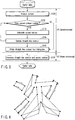
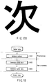
- the processing described in the reference document includes broadly two-staged processing of preprocessing by a CPU and main processing by a GPU. Namely, a vector format graphic is first decomposed into an assembly of triangles by the CPU. Thereafter, the respective triangles are rasterized by the GPU. The reason for this is that a unit of processing of the GPU is a triangle and the GPU cannot directly handle a graphic configured by straight lines and curves as shown in FIG. 2 .
- vector format data (hereinafter also referred to as “vector data”) is read from a storage medium such as an HDD or a RAM, and processing for analyzing the contours thereof is performed (step S101).
- the vector format data expressing the graphic of FIG. 2 are configured by points and straight lines as shown in FIG. 4 .
- end-points of the straight lines or the parameter curves of the graphic are expressed by black points, and control points of the parameter curves are expressed by white points.
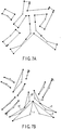
- two types of contour data as shown in FIGS. 5A and 5B are generated by analyzing such vector format data.
- the contour data of FIG. 5A is called “straight line contour”
- the contour data of FIG. 5B is called "curved contour".
- the curved contour of FIG. 5B is an assembly of triangles connecting three points of starting points, ending points, and control points of the parameter curves.
- the respective triangles circumscribe the parameter curves, and there are curves necessarily inside the triangles.
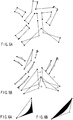
- the curved contours are classified into two types of curved contours as shown in FIGS. 6A and 6B .
- a concave area of the curve is at the inside of the graphic (hereinafter referred to as "concave curved contour")
- a convex area of the curve is at the inside of the graphic (hereinafter referred to as "convex curved contour").
- the straight line contours of FIG. 5A will be described.
- the straight line contours are polygons obtained by connecting the starting points and the ending points of the straight lines, the starting points and the ending points of the convex curved contours, and the starting points, the control points, and the ending points of the concave curved contours with line segments. Two points of a starting point and an ending point are connected on a convex curved contour while three points of a starting point, a control point, and an ending point are connected on a concave curved contour.
- polygons configuring the straight line contours are not necessarily limited to one (in this example, the straight line contours are configured by three polygons). Further, in some cases, the respective polygons may include self-intersections or holes.
- step S102 when the analysis on the contours of the vector format data is completed in step S101, it is examined whether or not there is overlapping on a generated curved contour (step S102). As a result, when overlapping is found, the routine proceeds to step S103 where processing is performed for subdividing a triangle whose area is larger between the overlapped two triangles (step S103). Because the straight line contours are changed under the influence of this subdividing processing, the straight line contours are updated (step S104). Thereafter, the routine returns to step S102 where it is examined again whether or not there is overlapping, and when there is no overlapping, the routine returns to step S105. Note that the processes in step S102 to S104 are repeated until no more overlaps exist.
- triangles a and b, and triangles c and d are overlapped. Therefore, the triangles a and c are respectively subdivided into two triangles a0 and bl, and c0 and c1 as shown in FIG. 7B . Then, the straight line contours are updated as shown in FIG. 7A .
- the polygons configuring the straight line contours are respectively divided into a plurality of triangles.
- the three polygons of FIG. 7A are divided into assemblies of triangles as shown in FIG. 8 .
- the triangles configuring the straight line contours ( FIG. 8 ) and the triangles configuring the curved contours ( FIG. 7B ) are rasterized by the GPU (step S106).
- the GPU step S106.
- all the pixels at the inside of the triangles configuring the straight line contours are rasterized.
- FIG. 9B only the concave areas on the concave curved contours or only the convex areas on the convex curved contours are rasterized among the pixels at the inside of the triangles configuring the curved contours.
- the results of rasterizing of the straight line contours and the curved contours obtained as described above are stored together in a frame buffer inside the GPU.
- the data shown in FIGS. 9A and 9B are respectively stored in the frame buffer as raster data as shown in FIG. 10 .
- the vector data storage unit 1 stores vector data of a graphic to be rasterized. As described in FIG. 4 , the vector data is composed of types of graphics primitives, coordinates of respective points configuring the graphics primitives, connecting relationship among the points, and the like.
- the vector data of the graphic of FIG. 2 is expressed as shown in FIG. 4 in the same manner as in the description described above.
- the end-points of the straight lines or the parameter lines are expressed by black points
- the control points of the parameter curves are expressed by white points.
- the vector data is not limited to the format described above, and may include other data generally utilized in the field of computer graphics.
- the vector data ( FIG. 4 ) stored in the vector data storage unit 1 is read by the triangular data generation unit 2.
- the triangular data generation unit 2 generates triangular data in accordance with a flow as shown in FIG. 11 by analyzing the contours of the read vector data.
- the straight line contours of the vector data are analyzed.
- polygons obtained by connecting the starting points and the ending points included in the vector data, the starting points and the ending points of the convex curved contours, and the starting points, the control points, and the ending points of the concave curved contours with line segments are defined as straight line contours.
- At least one polygon obtained by connecting, in disregard of the control points, only the starting points and ending points of the straight lines and curves included in the vector data with line segments is defined as a straight line contour.
- a straight line contour For example, as straight line contours analyzed from the vector data of FIG. 4 , three polygons P0, P1 and P2 as shown in FIG. 12 can be obtained (hereinafter, this will be described supposing that a plurality of polygons are obtained).
- step S202 making the straight line contour triangles is performed (step S202). Specifically, first, an arbitrary vertex among the plurality of vertices of the respective polygons configuring the straight line contours obtained in step S201 is selected (in this specification, this point is referred to as "pivot"). Then, with respect to each polygon, a plurality of triangles with the pivot being as one vertex are generated such that the pivot and all the other vertices on the polygon including the pivot are connected with straight lines, and two vertices coupled to each other become a side of one triangle. Where the two vertices coupled to each other mean two vertices connected with a side of a polygon.
- FIG. 12 For example, assuming that, in FIG. 12 , points 0, 23 and 28 are respectively selected as pivots for the three polygons P0, P1 and P2, a plurality of triangles as shown in FIG. 13 are generated. In FIG. 13 , a plurality of triangles are overlapped on one another, and it is difficult to understand the forms of the triangles only from this drawing. Therefore, for convenience, numbers of the three vertices configuring the plurality of triangles generated from the three polygons P0, P1 and P2 are shown in FIG. 14 .
- FIG. 14 is merely a supplement to make the description understandable, and does not express the triangular data themselves.
- the actual triangular data are composed of position coordinates of three points, texture coordinates, connecting relationships, and the like configuring the respective triangles.
- step S203 the curved contours of the vector data are analyzed.
- an assembly of triangles connecting three points of the starting points, the ending points, and the control points of the parameter curves included in the vector data is defined as a curved contour.
- the triangular data ( FIG. 13 ) of the straight line contours and the triangular data ( FIG. 5B ) of the curved contours which have been generated in accordance with the processing procedure as described above are output from the triangular data generation unit 2 and is stored in the triangular data storage unit 3.
- the procedure may be configured such that the processes of the above steps S201 and S202 are performed in parallel, so that triangles may be generated at the same time of analyzing straight line contours.
- the triangular data are composed of position coordinates of three points, texture coordinates, connecting relationships, and the like configuring the respective triangles.
- the configuration of the triangular data is not limited to this format, and may include other data generally utilized in the field of computer graphics.
- the stencil data generation unit 4 reads the triangular data stored in the triangular data storage unit 3, and generates stencil data by rasterizing pixels in the triangles.
- the stencil data is image data having the same resolution as that finally presented to the presentation unit 8. Note that the stencil data is stored in the stencil data storage unit 5. Further, numeric values of about several bits are assigned to the respective pixels of the stencil data, and those are initialized to 0 in advance of all drawings every frame.
- the stencil data generation unit 4 reads and rasterizes the triangular data of the straight line contours ( FIG. 13 ) and the triangular data of the curved contours ( FIG. 5B ) from the triangular data storage unit 3. At this time, all the pixels at the inside of the triangles of the straight line contours are rasterized.
- the rasterizing is performed such that pixels values of the stencil data at the inside of the triangles are bit-inverted for each triangle with respect to all the triangles shown in FIG. 13 .
- stencil data as shown in FIG. 15 is obtained.
- FIG. 15 among the pixels subjected to the bit-inversion processing with respect to all the triangles, areas whose pixel values are numeric values other than zero are filled with black, and areas whose pixel values are zero are filled with gray.
- the pixel values at the inside of the straight line contours are numeric values other than zero, and the pixel values at the outside are zero.
- the stencil data are updated as shown in FIG. 16B .
- the pixel values at the inside of the graphic of FIG. 1 provided initially are numeric values other than zero, and the pixel values at the outside are zero.
- the stencil data storage unit 5 stores the stencil data ( FIG. 16B ) generated by the stencil data generation unit 4.
- the stencil data is image data having the same resolution as that finally presented to the presentation unit 8.
- the configuration of the stencil data is not limited to this format, and may include other data generally utilized in the field of computer graphics.
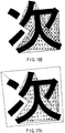
- the raster data generation unit 6 generates raster data such that only areas whose pixel values are numeric values other than zero (the areas filled with black in FIG. 16B ) are rasterized with reference to the stencil data stored in the stencil data storage unit 5.
- the raster data is image data having the same resolution as that finally presented to the presentation unit 8, and is stored in the raster data storage unit 7. Numeric values of about several bits are assigned to the respective pixels of the raster data for each of a plurality of color components (for example, RGBA).
- RGBA color components
- the raster data generation unit 6 rasterizes all the pixels at the inside of the two triangles covering the entire graphics.
- pixels which will be actually written into the raster data storage unit 7 among these pixels are limited to areas at which pixel values of corresponding stencil data are numeric values other than zero (the areas filled with black in FIG. 17A ).
- raster data as shown in FIG. 17B are written into the raster data storage unit 7.
- the raster data is image data having the same resolution as that finally presented to the presentation unit 8.
- the configuration of the raster data is not limited to this format, and may include other data generally utilized in the field of computer graphics.
- the presentation unit 8 is configured by a display, a printer, or the like for presenting the raster data stored in the raster data storage unit 7 to a user.
- a flowchart showing a procedure of processes of a rasterizing technique of FIG. 18 is compared with the flowchart shown in FIG. 3 .
- the preprocessing cost by the CPU as shown in FIG. 3 is only for the analysis on contours (step S301).
- the processes for generating stencil data (step S302) and generating raster data (step S303) are performed by the GPU. Therefore, it is possible to greatly reduce the preprocessing cost by the CPU. Accordingly, even when the geometrical form of the graphic is dynamically changed, rasterizing can be performed at high speed.
- a configuration of a image processing apparatus is the same as that in the first example, illustrations and detailed descriptions thereof are omitted.
- the embodiment is different from the first example in that the processing contents of the triangular data generation unit 2 and the stencil data generation unit 4 are different.
- the triangular data generation unit 2 makes polygons, which are obtained by simply connecting the starting points and ending points of the straight lines and curves which are included in the vector data with line segments, be straight line contours.
- the triangular data generation unit 2 makes polygons, which are obtained by connecting the starting points and the ending points of the straight lines, the starting points and the ending points of the convex curved contours, and the starting points, the control points, and the ending points of the concave curved contours which are included in the vector data with line segments, be straight line contours.
- the triangular data generation unit 2 generates a plurality of triangular data with a pivot being as one vertex, in the same manner as in the first example, with respect to the polygons by the analysis on the straight line contours.
- An example of generated triangular data is shown in FIG. 19 .
- a configuration type of the curved contours and a method for generating triangular data from the curved contours are the same as in the first example.
- the stencil data generation unit 4 reads and rasterizes the triangular data of the straight line contours ( FIG. 19 ) and the triangular data of the curved contours ( FIG. 5B ) from the triangular data storage unit 3 in the same manner as in the first example. At this time, with respect to the triangles of the straight line contours, all the pixels at the inside of the respective triangles are rasterized, so that pixel values of stencil data corresponding to these pixel positions are bit-inverted.
- stencil data as shown in FIG. 20 is obtained.
- FIG. 20 among the pixels which have been bit-inverted once or more, areas whose pixel values are numeric values other than zero are filled with black, and areas whose pixel values are zero are filled with gray.
- the stencil data generation unit 4 rasterizes only pixels belonging to the convex areas of the curves among the pixels at the inside of the triangles of the curved contours.
- the stencil data generation unit 4 rasterizes only concave areas of the concave curved contours or only convex areas of the convex curved contours among the pixels at the inside of the triangles of the curved contours, and bit-inverts pixel values of stencil data corresponding to these pixel positions.
- the stencil data is updated as shown in FIG. 21 B .
- the pixel values at the inside of the graphic of FIG. 2 provided initially are made to be numeric values other than zero, and pixel values at the outside are made to be zero.
- the procedure of processes of the rasterizing technique by the image processing apparatus according to the embodiment is substantially the same as the flowchart of the first example shown in FIG. 18 .
- the analysis technique on the straight line contours is different from that of the first example, and the same analysis as in the technique shown in FIGS. 5A and 5B is carried out.
- step S103 subdivision of the curved contours
- step S104 updating of the straight line contours
- a coverage data storage unit 9 and a raster data synthesis unit 10 are further provided to the image processing apparatus according to the first example and the embodiment.
- the coverage data storage unit 9 stores coverage data output from the stencil data generation unit 4.
- the coverage data is image data having the same resolution as that finally presented to the presentation unit 8. Numeric values of about several bits are assigned to respective pixels of the coverage data, and are initialized to 1 in advance of all drawings every frame.
- the stencil data generation unit 4 draws the stencil data by bit-inversion and outputs to the stencil data storage unit 5. At that time, the stencil data generation unit 4 draws an alpha value onto corresponding pixel positions of the coverage data remained in the coverage data storage unit 9.
- the stencil data generation unit 4 assigns values less than 1 to alpha values of the pixels positioned near the edge of the graphic among the rasterized pixels, and outputs the alpha values as coverage data to the coverage data storage unit 9.
- the raster data generation unit 6 generates raster data with a sub-pixel accuracy with reference to the coverage data stored in the coverage data storage unit 9, and outputs the data to the raster data storage unit 7.
- the raster data generation unit 6 assigns color values of pixels rasterized this time with respect to all the sub-pixels included in the pixel.
- the raster data generation unit 6 assigns the color values of the pixels rasterized this time with respect to some of the sub-pixels included in the pixels, and stores the already assigned color values directly with respect to the remaining sub-pixels. Note that the sub-pixels to which the color values are assigned are selected on the basis of a size of the coverage.
- the raster data storage unit 7 stores raster data with a sub-pixel accuracy generated by the raster data generation unit 6, and raster data with a pixel accuracy synthesized by the raster data synthesis unit 10.
- the raster data synthesis unit 10 synthesizes the raster data with a sub-pixel accuracy stored in the raster data storage unit 7, and transforms the data into raster data having the same resolution (pixel accuracy) as that finally presented to the presentation unit 8.
- alpha blending has been used for anti-aliasing. For this reason, all the graphics objects must be depth-sorted, and rasterized in order of graphic at a deeper position.
- anti-aliasing can be carried out at high speed because alpha blending at a high processing cost is not used.
- the respective examples and the embodiment basically describe examples in which graphics including parameter curves (for example, quadratic Bezier curves) are rasterized.
- the third example is one in which even a graphic including cubic Bezier curves can be handled in the same manner as the graphic including parameter curves (for example, quadratic Bezier curves) as described above. Note that, because the processing procedure thereof is the same as that of the first example, illustrations thereof are omitted. Further, descriptions thereof overlapped onto those of the first example are also omitted.
- FIG. 23 is a view showing an example of a graphic including cubic Bezier curves. Suppose that the graphic of FIG. 23 is stored in the vector data storage unit 1 as vector data as shown in FIG. 24 .
- the triangular data generation unit 2 analyzes the vector data shown in FIG. 24 , and generates the straight line contours shown in FIG. 25A and the curved contours shown in FIG. 25B in the same manner as in the first example.
- the end-points of the straight lines or the parameter curves on the graphic are expressed by black points
- the control points of the parameter curves are expressed by white points.
- the control points of a parameter curve are two points with respect to the end-points of the parameter curve, and a triangle is formed such that one control point is connected to an endpoint positioned diagonally.
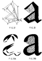
- the raster data with respect to the curved contours is determined by a curve as shown in FIG. 26A . However, this may be determined by a curve having an inflection point as shown in FIG. 26B .
- the triangular data generation unit 2 generates a plurality of triangle with the pivot being as one vertex such that, as shown in FIG. 27 , a pivot (0 point in FIG. 27 ) and all the other vertices in the triangles including the pivot are connected with straight lines, and two vertices coupled to each other become a side of one triangle.
- the stencil data generation unit 4 rasterizes the triangular data prepared by the triangular data generation unit 2 in the same manner as in the first example. As a consequence, rasterized stencil data shown in FIG. 28 can be obtained. Finally, in the same manner as in the first example, the stencil data generation unit 4 generates stencil data as shown in FIG. 29B from the stencil data obtained from the triangular data by the straight line contours ( FIG. 28 ) and the stencil data obtained from the triangular data by the curved contours ( FIG. 29A ). Then, all the pixels at the inside of the two triangles covering the entire graphic as shown in FIG. 30A are finally rasterized.
- pixels which will be actually written into the raster data storage unit 7 among these pixels are limited to an area at which pixel values of corresponding stencil data are numeric values other than zero (the area filled with black in FIG. 30A ).
- raster data as shown in FIG. 30B is written into the raster data storage unit 7. Note that, because the detailed processes in this case are the same as those in the first example, descriptions thereof are omitted.
- the present example provides a new rasterizing technique in which the preprocessing cost is greatly reduced. As a result, even when a geometrical form of a graphic is dynamically changed, rasterizing can be carried out at high speed.
- the present example provides a new anti-aliasing technique which does not require alpha blending.
- depth-sorting whose processing cost is high is no longer required, and it is possible to apply anti-aliasing at high speed.
- the above-described examples and the embodiment have described the cases in which raster format graphic data is generated from vector format graphic data with respect to a character.
- the present invention can be applied to a case when another graphic, for example map data, is provided in a vector format, and raster format graphic data is generated from the map data.
- rasterizing can be performed at high speed even when a geometrical form of a graphic is dynamically changed. Further, it is possible to apply anti-aliasing at high speed without using alpha blending with a high processing cost.
Landscapes
- Engineering & Computer Science (AREA)
- Physics & Mathematics (AREA)
- General Physics & Mathematics (AREA)
- Theoretical Computer Science (AREA)
- Computer Hardware Design (AREA)
- Image Generation (AREA)
Claims (8)
- Bildverarbeitungsvorrichtung, umfassend:eine erste Datenerzeugungseinheit (2), die trianguläre Daten erzeugt, indem geradlinige Konturen und gekrümmte Konturen in Bezug auf Vektorformatgrafikdaten analysiert werden und aus den geradlinigen Konturen und den gekrümmten Konturen Dreiecke gebildet werden;eine zweite Datenerzeugungseinheit (4), die aus den triangulären Daten Schablonendaten erzeugt;eine dritte Datenerzeugungseinheit (6), die Rasterformatgrafikdaten in Bezug auf die Schablonendaten erzeugt;wobeidie erste Datenerzeugungseinheit wenigstens ein Polygon erzeugt durch Analysieren der geradlinigen Konturen der Vektorformatgrafikdaten, und wobei sie eine Mehrzahl von Dreiecken in Bezug auf jedes Polygon so erzeugt, dass ein Eckpunkt eines Polygons zu einem gemeinsamen Eckpunkt der Mehrzahl von Dreiecken gemacht wird, wobei der gemeinsame Eckpunkt und alle anderen Eckpunkte durch gerade Linien verbunden sind, und wobei zwei miteinander gekoppelte Eckpunkte zu einer Seite eines Dreiecks werden; und wobeidie zweite Datenerzeugungseinheit die Schablonendaten durch Bit intervieren von Pixeln auf der Innenseite der Mehrzahl von Dreiecken und durch Bit invertieren nur von Pixeln auf der Innenseite der Dreiecke mit gekrümmten Konturen, zu denen konkave oder konvexe Bereiche von Krümmungen gehören, erzeugt, wobei die Bereiche auf der Basis der gekrümmten Konturen erzeugt werden.
- Vorrichtung nach Anspruch 1, ferner eine Präsentationseinheit (8) umfassend, welche die Rasterformatgrafikdaten präsentiert.
- Vorrichtung nach Anspruch 1, wobei die durch die gekrümmten Konturen definierten Krümmungen Parameterkurven sind.
- Vorrichtung nach Anspruch 1, wobei die zweite Datenerzeugungseinheit Werte von kleiner 1 Alphawerten von Pixeln zuweist, die nahe einer Kante einer Grafik unter gerasterten Pixeln positioniert sind.
- Vorrichtung nach Anspruch 4, ferner eine Speichereinheit (9) umfassend, die als Umfangsdaten Alphawerte von Pixeln speichert, die von der zweiten Datenerzeugungseinheit ausgegeben werden.
- Vorrichtung nach Anspruch 5, ferner umfassend eine Rasterdatensyntheseeinheit (10), welche die Rasterdaten auf der Basis der in der Speichereinheit gespeicherten Rasterdaten synthetisiert.
- Computer-implementiertes Bildverarbeitungsverfahren, umfassend:Analysieren, durch die Bildverarbeitungsvorrichtung, geradliniger Konturen und gekrümmter Konturen in Bezug auf Vektorformatgrafikdaten, und Erzeugen triangulärer Daten durch Bilden von Dreiecke aus den geradlinigen Konturen und den gekrümmten Konturen;Erzeugen, durch die Bildverarbeitungsvorrichtung, von Schablonendaten aus den triangulären Daten;Erzeugen, durch die Bildverarbeitungsvorrichtung, von Rasterformatgrafikdaten in Bezug auf die Schablonendaten;wobeidas Erzeugen der triangulären Daten das Erzeugen wenigstens eines Polygon aufweist durch Analysieren der geradlinigen Konturen der Vektorformatgrafikdaten, und Erzeugen einer Mehrzahl von Dreiecken in Bezug auf jedes Polygon, so dass ein Eckpunkt eines Polygons zu einem gemeinsamen Eckpunkt der Mehrzahl von Dreiecken gemacht wird, wobei der gemeinsame Eckpunkt und alle anderen Eckpunkte durch gerade Linien verbunden sind, und wobei zwei miteinander gekoppelte Eckpunkte zu einer Seite eines Dreiecks werden; und wobeidas Erzeugen der Schablonendaten das Erzeugen der Schablonendaten durch Bit intervieren von Pixeln auf der Innenseite der Mehrzahl von Dreiecken und durch Bit invertieren nur von Pixeln auf der Innenseite der Dreiecke mit gekrümmten Konturen aufweist, zu denen konkave oder konvexe Bereiche von Krümmungen gehören, wobei die Bereiche auf der Basis der gekrümmten Konturen erzeugt werden.
- Computerlesbares Speichermedium mit darin eingebetteten, mittels Computer ausführbarer Anweisungen, wobei die Anweisungen, wenn sie durch einen Prozessor ausgeführt werden, es bewirken, dass der Prozessor ein Verfahren ausführt, das folgendes umfasst:Analysieren geradliniger Konturen und gekrümmter Konturen in Bezug auf Vektorformatgrafikdaten, und Erzeugen triangulärer Daten durch Bilden von Dreiecken aus den geradlinigen Konturen und den gekrümmten Konturen;Erzeugen von Schablonendaten aus den triangulären Daten;Erzeugen von Rasterformatgrafikdaten in Bezug auf die Schablonendaten;wobeidas Erzeugen der triangulären Daten das Erzeugen wenigstens eines Polygon aufweist durch Analysieren der geradlinigen Konturen der Vektorformatgrafikdaten, und Erzeugen einer Mehrzahl von Dreiecken in Bezug auf jedes Polygon, so dass ein Eckpunkt eines Polygons zu einem gemeinsamen Eckpunkt der Mehrzahl von Dreiecken gemacht wird, wobei der gemeinsame Eckpunkt und alle anderen Eckpunkte durch gerade Linien verbunden sind, und wobei zwei miteinander gekoppelte Eckpunkte zu einer Seite eines Dreiecks werden; und wobeidas Erzeugen der Schablonendaten das Erzeugen der Schablonendaten durch Bit intervieren von Pixeln auf der Innenseite der Mehrzahl von Dreiecken und durch Bit invertieren nur von Pixeln auf der Innenseite der Dreiecke mit gekrümmten Konturen aufweist, zu denen konkave oder konvexe Bereiche von Krümmungen gehören, wobei die Bereiche auf der Basis der gekrümmten Konturen erzeugt werden.
Applications Claiming Priority (1)
| Application Number | Priority Date | Filing Date | Title |
|---|---|---|---|
| JP2006066274A JP4693660B2 (ja) | 2006-03-10 | 2006-03-10 | 描画装置、描画方法及び描画プログラム |
Publications (3)
| Publication Number | Publication Date |
|---|---|
| EP1833024A2 EP1833024A2 (de) | 2007-09-12 |
| EP1833024A3 EP1833024A3 (de) | 2012-11-07 |
| EP1833024B1 true EP1833024B1 (de) | 2017-08-09 |
Family
ID=38137358
Family Applications (1)
| Application Number | Title | Priority Date | Filing Date |
|---|---|---|---|
| EP07250803.9A Active EP1833024B1 (de) | 2006-03-10 | 2007-02-27 | Bildverarbeitungsvorrichtung, Bildverarbeitungsverfahren und Bildverarbeitungsprogramm |
Country Status (5)
| Country | Link |
|---|---|
| US (1) | US7817152B2 (de) |
| EP (1) | EP1833024B1 (de) |
| JP (1) | JP4693660B2 (de) |
| KR (1) | KR100834596B1 (de) |
| CN (1) | CN101114380A (de) |
Families Citing this family (37)
| Publication number | Priority date | Publication date | Assignee | Title |
|---|---|---|---|---|
| US7831098B2 (en) * | 2006-11-07 | 2010-11-09 | Recognition Robotics | System and method for visual searching of objects using lines |
| CN101211416B (zh) * | 2006-12-26 | 2010-08-11 | 北京北大方正电子有限公司 | 矢量图形光栅化过程中的边界生成方法及系统、制造方法 |
| KR101383716B1 (ko) * | 2007-08-17 | 2014-04-10 | 삼성디스플레이 주식회사 | 전기 영동 표시 장치의 구동 장치 및 구동 방법 |
| US7982749B2 (en) * | 2008-01-31 | 2011-07-19 | Microsoft Corporation | Server-based rasterization of vector graphics |
| JP2009301284A (ja) * | 2008-06-12 | 2009-12-24 | Toshiba Corp | 描画装置および方法 |
| CN101661741B (zh) * | 2008-08-29 | 2012-02-22 | 富士通株式会社 | 图形光栅扫描中的三角形遍历方法和装置 |
| JP2010066157A (ja) * | 2008-09-11 | 2010-03-25 | Shimadzu Corp | コーンビームx線ct装置 |
| GB0818277D0 (en) * | 2008-10-06 | 2008-11-12 | Advanced Risc Mach Ltd | Graphics processing system |
| GB0818280D0 (en) * | 2008-10-06 | 2008-11-12 | Advanced Risc Mach Ltd | Graphics processing systems |
| GB0818279D0 (en) * | 2008-10-06 | 2008-11-12 | Advanced Risc Mach Ltd | Graphics processing systems |
| GB0818278D0 (en) * | 2008-10-06 | 2008-11-12 | Advanced Risc Mach Ltd | Graphics processing systems |
| DE102008057512A1 (de) * | 2008-11-15 | 2010-07-01 | Diehl Aerospace Gmbh | Verfahren zur Darstellung von Linienzügen |
| CN101753767B (zh) * | 2008-12-15 | 2013-02-27 | 富士通株式会社 | 用在图形光栅扫描中的凸多边形遍历方法和系统 |
| JP2010256985A (ja) * | 2009-04-21 | 2010-11-11 | Toshiba Corp | 描画装置および方法 |
| JP2010256986A (ja) * | 2009-04-21 | 2010-11-11 | Toshiba Corp | 描画装置および方法 |
| JP5443482B2 (ja) * | 2009-05-21 | 2014-03-19 | パナソニック株式会社 | グラフィクス描画装置、グラフィクス描画方法、グラフィクス描画プログラム、グラフィクス描画プログラムを記録した記録媒体、グラフィクス描画用集積回路 |
| CN101901590B (zh) * | 2009-05-25 | 2013-01-16 | 富士通株式会社 | 用于抗锯齿的多边形栅格化的方法和系统 |
| JP5458771B2 (ja) * | 2009-09-24 | 2014-04-02 | 株式会社島津製作所 | 放射線断層像撮影装置 |
| US20110285736A1 (en) | 2010-05-21 | 2011-11-24 | Kilgard Mark J | Decomposing cubic bèzier segments for tessellation-free stencil filling |
| US8457348B2 (en) * | 2010-06-28 | 2013-06-04 | The Chinese University Of Hong Kong | Producing structure-based ASCII pictures |
| JP2012027543A (ja) * | 2010-07-20 | 2012-02-09 | Toshiba Corp | 描画装置、描画方法、及び描画プログラム |
| JP5653277B2 (ja) | 2011-03-31 | 2015-01-14 | 株式会社東芝 | 描画装置、描画方法、及び描画プログラム |
| CN102722902B (zh) * | 2011-05-06 | 2016-05-04 | 新奥特(北京)视频技术有限公司 | 一种图形渲染流水线中光栅化阶段反走样的改进方法 |
| CN102737401A (zh) * | 2011-05-06 | 2012-10-17 | 新奥特(北京)视频技术有限公司 | 一种图形渲染中光栅化阶段的三角片填充方法 |
| CN102736947A (zh) * | 2011-05-06 | 2012-10-17 | 新奥特(北京)视频技术有限公司 | 一种图形渲染中光栅化阶段的多线程实现方法 |
| US9224218B2 (en) | 2012-06-05 | 2015-12-29 | Apple Inc. | System and method for loading and rendering curved features in a map |
| US9619853B2 (en) * | 2012-08-09 | 2017-04-11 | Qualcomm Incorporated | GPU-accelerated path rendering |
| JP6150560B2 (ja) * | 2013-03-01 | 2017-06-21 | 株式会社Screenホールディングス | データ変換方法、描画システムおよびプログラム |
| US9779534B2 (en) * | 2013-08-28 | 2017-10-03 | Qualcomm Incorporated | Prefixed summed length in graphics processing |
| KR102238651B1 (ko) | 2014-04-23 | 2021-04-09 | 삼성전자주식회사 | 경로 렌더링을 수행하는 방법 및 장치. |
| KR102443697B1 (ko) | 2015-09-11 | 2022-09-15 | 삼성전자주식회사 | 경로 스트로크를 수행하는 방법 및 장치 |
| US9792517B2 (en) * | 2016-02-12 | 2017-10-17 | Wacom Co., Ltd. | Method and system for generating and selectively outputting two types of ink vector data |
| US10049289B2 (en) | 2016-02-12 | 2018-08-14 | Wacom Co., Ltd. | Method and system for generating and selectively outputting two types of ink vector data |
| CN108805957B (zh) * | 2018-06-07 | 2022-06-24 | 青岛九维华盾科技研究院有限公司 | 一种基于位图图像自适应分割的矢量图生成方法及系统 |
| JP7552192B2 (ja) * | 2020-09-24 | 2024-09-18 | 株式会社ニューフレアテクノロジー | データ生成方法、荷電粒子ビーム照射装置及びプログラム |
| JP7639608B2 (ja) * | 2021-08-10 | 2025-03-05 | 株式会社ニューフレアテクノロジー | データ生成方法、荷電粒子ビーム照射装置及びプログラム |
| JP2024171036A (ja) * | 2023-05-29 | 2024-12-11 | 株式会社ニューフレアテクノロジー | 描画データ検査方法、描画方法、描画装置、およびプログラム |
Family Cites Families (9)
| Publication number | Priority date | Publication date | Assignee | Title |
|---|---|---|---|---|
| US4901251A (en) * | 1986-04-03 | 1990-02-13 | Advanced Micro Devices, Inc. | Apparatus and methodology for automated filling of complex polygons |
| JP2001109454A (ja) * | 1999-10-12 | 2001-04-20 | Fuji Xerox Co Ltd | 文字処理装置 |
| JP3552105B2 (ja) | 2000-05-26 | 2004-08-11 | シャープ株式会社 | 図形表示装置、文字表示装置、表示方法、記録媒体およびプログラム |
| CN1238819C (zh) * | 2000-12-05 | 2006-01-25 | 松下电器产业株式会社 | 三维字符生成设备及三维图形数据生成设备 |
| JP4028979B2 (ja) * | 2000-12-05 | 2008-01-09 | 松下電器産業株式会社 | 3次元図形データ生成装置 |
| JP2003091737A (ja) * | 2001-07-13 | 2003-03-28 | Sony Computer Entertainment Inc | 描画処理装置、描画処理プログラムを記録した記録媒体、描画処理プログラム、描画処理方法 |
| JP2005100177A (ja) * | 2003-09-25 | 2005-04-14 | Sony Corp | 画像処理装置およびその方法 |
| US7239319B2 (en) * | 2004-08-27 | 2007-07-03 | Microsoft Corporation | Rendering outline fonts |
| US7432937B2 (en) * | 2005-06-30 | 2008-10-07 | Intel Corporation | System and method for concave polygon rasterization |
-
2006
- 2006-03-10 JP JP2006066274A patent/JP4693660B2/ja not_active Expired - Lifetime
- 2006-09-26 US US11/535,277 patent/US7817152B2/en active Active
- 2006-10-23 KR KR1020060102858A patent/KR100834596B1/ko active Active
-
2007
- 2007-02-27 EP EP07250803.9A patent/EP1833024B1/de active Active
- 2007-03-09 CN CNA2007100862361A patent/CN101114380A/zh active Pending
Also Published As
| Publication number | Publication date |
|---|---|
| EP1833024A2 (de) | 2007-09-12 |
| US7817152B2 (en) | 2010-10-19 |
| KR20070092586A (ko) | 2007-09-13 |
| US20070211061A1 (en) | 2007-09-13 |
| EP1833024A3 (de) | 2012-11-07 |
| CN101114380A (zh) | 2008-01-30 |
| JP2007241878A (ja) | 2007-09-20 |
| JP4693660B2 (ja) | 2011-06-01 |
| KR100834596B1 (ko) | 2008-06-02 |
Similar Documents
| Publication | Publication Date | Title |
|---|---|---|
| US7817152B2 (en) | Image processing apparatus, image processing method, and image processing program | |
| US7821514B2 (en) | Image processing apparatus, image processing method, and image processing program | |
| EP3039652B1 (de) | Vorbestimmte gesamtlänge in einer grafikverarbeitung | |
| JP4937359B2 (ja) | 図形描画装置及び図形描画方法 | |
| US7868887B1 (en) | Rendering rational quadratic Bézier curves on a GPU | |
| US10102663B2 (en) | Gradient adjustment for texture mapping for multiple render targets with resolution that varies by screen location | |
| US8773439B2 (en) | Approximation of stroked higher-order curved segments by quadratic bèzier curve segments | |
| US10332290B2 (en) | Fast, coverage-optimized, resolution-independent and anti-aliased graphics processing | |
| KR102666054B1 (ko) | 그래픽 처리 시스템 | |
| EP1630745A2 (de) | Darstellung eines Konturschrifttypen | |
| US8068106B1 (en) | Rendering cubic Bézier curves as quadratic curves using a GPU | |
| JP2009301284A (ja) | 描画装置および方法 | |
| US20230082839A1 (en) | Rendering scalable raster content | |
| Kokojima et al. | Resolution independent rendering of deformable vector objects using graphics hardware | |
| US11776179B2 (en) | Rendering scalable multicolored vector content | |
| JP2010256986A (ja) | 描画装置および方法 | |
| JP2010256985A (ja) | 描画装置および方法 |
Legal Events
| Date | Code | Title | Description |
|---|---|---|---|
| PUAI | Public reference made under article 153(3) epc to a published international application that has entered the european phase |
Free format text: ORIGINAL CODE: 0009012 |
|
| 17P | Request for examination filed |
Effective date: 20070305 |
|
| AK | Designated contracting states |
Kind code of ref document: A2 Designated state(s): AT BE BG CH CY CZ DE DK EE ES FI FR GB GR HU IE IS IT LI LT LU LV MC NL PL PT RO SE SI SK TR |
|
| AX | Request for extension of the european patent |
Extension state: AL BA HR MK YU |
|
| PUAL | Search report despatched |
Free format text: ORIGINAL CODE: 0009013 |
|
| AK | Designated contracting states |
Kind code of ref document: A3 Designated state(s): AT BE BG CH CY CZ DE DK EE ES FI FR GB GR HU IE IS IT LI LT LU LV MC NL PL PT RO SE SI SK TR |
|
| AX | Request for extension of the european patent |
Extension state: AL BA HR MK RS |
|
| RIC1 | Information provided on ipc code assigned before grant |
Ipc: G09G 5/24 20060101ALI20121001BHEP Ipc: G06T 11/00 20060101AFI20121001BHEP |
|
| 17Q | First examination report despatched |
Effective date: 20130605 |
|
| AKX | Designation fees paid |
Designated state(s): DE FR GB |
|
| RAP1 | Party data changed (applicant data changed or rights of an application transferred) |
Owner name: SAMSUNG ELECTRONICS CO., LTD. |
|
| GRAP | Despatch of communication of intention to grant a patent |
Free format text: ORIGINAL CODE: EPIDOSNIGR1 |
|
| INTG | Intention to grant announced |
Effective date: 20160718 |
|
| GRAJ | Information related to disapproval of communication of intention to grant by the applicant or resumption of examination proceedings by the epo deleted |
Free format text: ORIGINAL CODE: EPIDOSDIGR1 |
|
| INTC | Intention to grant announced (deleted) | ||
| GRAP | Despatch of communication of intention to grant a patent |
Free format text: ORIGINAL CODE: EPIDOSNIGR1 |
|
| INTG | Intention to grant announced |
Effective date: 20170217 |
|
| GRAS | Grant fee paid |
Free format text: ORIGINAL CODE: EPIDOSNIGR3 |
|
| GRAA | (expected) grant |
Free format text: ORIGINAL CODE: 0009210 |
|
| AK | Designated contracting states |
Kind code of ref document: B1 Designated state(s): DE FR GB |
|
| REG | Reference to a national code |
Ref country code: GB Ref legal event code: FG4D |
|
| REG | Reference to a national code |
Ref country code: DE Ref legal event code: R096 Ref document number: 602007051904 Country of ref document: DE |
|
| REG | Reference to a national code |
Ref country code: FR Ref legal event code: PLFP Year of fee payment: 12 |
|
| REG | Reference to a national code |
Ref country code: DE Ref legal event code: R097 Ref document number: 602007051904 Country of ref document: DE |
|
| PLBE | No opposition filed within time limit |
Free format text: ORIGINAL CODE: 0009261 |
|
| STAA | Information on the status of an ep patent application or granted ep patent |
Free format text: STATUS: NO OPPOSITION FILED WITHIN TIME LIMIT |
|
| 26N | No opposition filed |
Effective date: 20180511 |
|
| P01 | Opt-out of the competence of the unified patent court (upc) registered |
Effective date: 20230520 |
|
| PGFP | Annual fee paid to national office [announced via postgrant information from national office to epo] |
Ref country code: FR Payment date: 20251231 Year of fee payment: 20 |
|
| PGFP | Annual fee paid to national office [announced via postgrant information from national office to epo] |
Ref country code: GB Payment date: 20260106 Year of fee payment: 20 |
|
| PGFP | Annual fee paid to national office [announced via postgrant information from national office to epo] |
Ref country code: DE Payment date: 20260102 Year of fee payment: 20 |