EP1833030A1 - Panneau de verre et systeme de detection de rupture du panneau de verre - Google Patents
Panneau de verre et systeme de detection de rupture du panneau de verre Download PDFInfo
- Publication number
- EP1833030A1 EP1833030A1 EP05805215A EP05805215A EP1833030A1 EP 1833030 A1 EP1833030 A1 EP 1833030A1 EP 05805215 A EP05805215 A EP 05805215A EP 05805215 A EP05805215 A EP 05805215A EP 1833030 A1 EP1833030 A1 EP 1833030A1
- Authority
- EP
- European Patent Office
- Prior art keywords
- glass
- glass sheet
- antenna
- glass panel
- reader
- Prior art date
- Legal status (The legal status is an assumption and is not a legal conclusion. Google has not performed a legal analysis and makes no representation as to the accuracy of the status listed.)
- Withdrawn
Links
Images


Classifications
-
- G—PHYSICS
- G08—SIGNALLING
- G08B—SIGNALLING SYSTEMS, e.g. PERSONAL CALLING SYSTEMS; ORDER TELEGRAPHS; ALARM SYSTEMS
- G08B13/00—Burglar, theft or intruder alarms
- G08B13/02—Mechanical actuation
- G08B13/04—Mechanical actuation by breaking of glass
-
- E—FIXED CONSTRUCTIONS
- E06—DOORS, WINDOWS, SHUTTERS, OR ROLLER BLINDS IN GENERAL; LADDERS
- E06B—FIXED OR MOVABLE CLOSURES FOR OPENINGS IN BUILDINGS, VEHICLES, FENCES OR LIKE ENCLOSURES IN GENERAL, e.g. DOORS, WINDOWS, BLINDS, GATES
- E06B7/00—Special arrangements or measures in connection with doors or windows
- E06B7/28—Other arrangements on doors or windows, e.g. door-plates, windows adapted to carry plants, hooks for window cleaners
-
- Y—GENERAL TAGGING OF NEW TECHNOLOGICAL DEVELOPMENTS; GENERAL TAGGING OF CROSS-SECTIONAL TECHNOLOGIES SPANNING OVER SEVERAL SECTIONS OF THE IPC; TECHNICAL SUBJECTS COVERED BY FORMER USPC CROSS-REFERENCE ART COLLECTIONS [XRACs] AND DIGESTS
- Y10—TECHNICAL SUBJECTS COVERED BY FORMER USPC
- Y10T—TECHNICAL SUBJECTS COVERED BY FORMER US CLASSIFICATION
- Y10T428/00—Stock material or miscellaneous articles
- Y10T428/31—Surface property or characteristic of web, sheet or block
- Y10T428/315—Surface modified glass [e.g., tempered, strengthened, etc.]
Definitions
- the present invention relates to a glass panel and a glass panel damage detection system.
- Alarm devices of this type respond to a situation where a window is forced open or a window pane is broken, by sounding an alarm or by indicating the incidence by an alarm light. With this, tenants, neighbors or the security company can know that the window is forced open or the window pane is damaged.
- a network of electric circuits is provided on the glass surface of the window pane (see, for example, patent document No. 1).
- damage to the window pane is detected by disconnection of the electric circuit, and an alarm device is activated accordingly.
- the electric circuit Due to the wiring between the electric circuit and the detecting device in this window pane damage detection system, the electric circuit should be provided in substantially the entirety of the surface of the glass, with the result that the appearance of the window pane and the neighborhood thereof may be impaired.
- a general purpose of the present invention is to detect damage to a glass panel with a simple structure and without materially impairing the appearance.
- a glass panel according to first embodiment of the present invention comprises: a glass sheet formed of tempered glass; an antenna provided on the surface of the glass sheet; and a wireless chip connected to the antenna and operative to wirelessly transmit, via the antenna, identification information in response to a request from an external source.
- a glass panel according to second embodiment comprises: a first glass sheet and a second glass sheet, at least one of the first glass sheet and the second glass sheet being formed of tempered glass; an anchoring frame operative to fix the first glass sheet and the second glass sheet so as to be parallel and opposite to each other so that an air gap layer is formed between the first glass sheet and the second glass sheet; an antenna provided on at least one of the first glass sheet and the second glass sheet which is formed of tempered glass; a wireless chip connected to the antenna and operative to wirelessly transmit, via the antenna, identification information in response to a request from an external source.
- the antenna of the glass panel according to said the second embodiment may be provided on the surface of at least one of the first glass sheet and the second glass sheet which is formed of tempered glass so as to face the air gap layer.
- the wireless chip of the glass panel according to the first embodiment or the second embodiment may be driven by electromotive force provided by an electromagnetic wave received from an external source. Since a wireless chip of passive type does not have a built-in power supply and is smaller than the chip of active type, the appearance of the glass panel is maintained more successfully, and maintenance of the glass panel in relation to a power supply is not necessary.
- An embodiment of glass panel damage detection system of the present invention comprises: the aforementioned glass panel; a reader operative to wirelessly obtain, via the antenna, identification information from the wireless chip; and an alarm device operative, when the reader fails to obtain the identification information properly in response to a request from the reader to the wireless chip, to alert of the failure.
- damage to a glass panel is detected with a simple structure and without materially impairing the appearance.
- a glass panel damage detection system 12 according to the first embodiment of the present invention which includes a glass panel 10.
- the use of the glass panel 10 according to the first embodiment as a window for a building will be described by way of example.
- the glass panel damage detection system 12 according to the embodiment is configured such that an antenna for an IC tag is adhesively attached to tempered glass so that damage to the glass is detected as a result of disconnection between the antenna and the chip occurring when the glass sheet is broken.
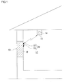
- Fig. 1 shows the structure of the glass panel damage detection system 12 according to the embodiment of the present invention.
- the glass panel damage detection system 12 is provided with a glass panel 10, a reader 14 and an alarm device 16.
- the glass panel 10 is provided with a glass sheet 18, an RFID (radio frequency identification) tag 20.
- the glass sheet 18 is formed of tempered glass.
- High strength of tempered glass results from high compression stress at the surface.
- Tempered glass is produced by, for example, heating glass to a temperature close to the softening point, blowing compressed air flow to the glass surface and then rapidly cooling the glass surface. By rapidly cooling the glass surface, a compression stress layer is formed on the surface of the glass and a tensile stress layer inside is formed inside.
- a force exceeding the limit of compression stress on the surface is applied to a part of the tempered glass, a network of cracks develop at a high speed on the entirety of the surface of the tempered glass. The glass is broken into pieces without being dropped.
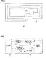
- Fig. 2 shows the appearance of the RFID tag 20.
- the RFID tag 20 is provided with an antenna 22 and a ID chip 24 (wireless chip) for wirelessly transmitting, via the antenna 22, identification information in response to a request from an external source.
- ID chip 24 wireless chip
- the antenna 22 is adhesively attached to the surface of the glass sheet 18 so as to face the inside.
- the antenna 22 in this embodiment is pasted onto the glass sheet 18.
- the antenna 22 may be provided on the glass sheet 18 by plating, transfer printing, painting, coating or vapor deposition.
- the antenna 22 in this embodiment is provided on the glass sheet 18 so as to face the inside.
- the antenna 22 may be provided on the surface of the glass sheet 18 so as to face the outside. It is preferable, however, to provide the antenna 22 on the surface of the glass sheet 18 so as to face the inside for suppression of corrosion, degradation, robbery or tampering.
- the ID chip 24 is of so-called passive type driven by electromotive force provided by an electromagnetic wave received from an external source. For this reason, onsite (i.e., the glass panel 10 and the neighborhood thereof) maintenance of the ID chip 24 in relation to a power supply is not necessary.
- Fig. 3 shows the functional blocks of the ID chip 24.
- the ID chip 24 is provided with a receiver circuit 26, a rectifier circuit 28, a memory 40, a control circuit 42 and a transmitter circuit 44.
- the receiver circuit 26 outputs an electromagnetic wave received by the antenna 22 to the rectifier circuit 28 and generates a clock signal from the electromagnetic wave received by the antenna 22 for output to the control circuit 42.
- the rectifier circuit 28 rectifies the electromagnetic wave received by the receiver 26, converts the rectified wave to electric power and outputs the power to the control circuit 42 to drive the circuit 42.
- the memory 44 stores the identification information.
- the identification information stored in the memory 40 includes, for example, information related to the fabrication, components, functions and distribution of the glass sheet 18 but is not limited to these. If the RFID tag 20 is only used to detect damage to the glass panel 10, the contents of information do not matter and only the identification may be provided.
- the control circuit 42 Upon receipt of the clock signal from the receiver circuit 26, the control circuit 42 retrieves the identification information from the memory 40 and outputs an information signal associated with the identification information to the transmitter circuit 44 along with a signal for transmission.
- the transmitter circuit 44 modulates, with the information signal, the signal for transmission fed by the control circuit 42 and outputs the modulated signal to the antenna 22.
- the antenna 22 transmits the signal modulated by the transmitter circuit 44.
- the signal transmitted from the antenna 22 is received by the reader 14.
- the RFID tag 20 Since the RFID tag 20 is small, provision thereof on the surface of the glass sheet 18 hardly impairs the appearance.
- the RFID tag 20 may be provided at an easily viewable position (e.g. the center) of the surface of the glass sheet 18. By providing the RFID tag 20 at an easily viewable position on the surface of the glass sheet 18, whether the window is open or closed can be known depending on whether the RFID tag 20 is viewed.
- Fig. 4 shows the functional blocks of the reader 14.
- the reader 14 obtains the identification information from the ID chip 24 by wireless communication via the antenna 20 of the RFID tag 20.
- the reader 14 comes with various sizes and shapes.
- the reader 14 may be portable, having the size of a card.
- the reader 14 is provided with a transmitter circuit 46, an antenna 48, a receiver circuit 50, a control circuit 52 and an alarm device 16.
- the transmitter circuit 46 generates an electromagnetic wave, transmits the electromagnetic wave to the RFID 20 via the antenna 48, and transmits a signal including the identification information and transmitted from the RFID tag 20.
- the receiver circuit 50 retrieves, from the received signal, the identification information stored in the ID chip 24 and outputs the information to the control circuit 52.
- the alarm device 16 alerts of the failure.
- Failure to properly obtain the identification information encompasses cases different from normal obtaining of the identification information including: i) cases where the identification information cannot be obtained; ii) cases where there is a mixture of failure to obtain the identification information and successful obtaining of the identification information; iii) cases where only a part of the identification information is obtained; iv) cases where wrong identification information is obtained; v) cases where it takes time to obtain the identification information, or vi) cases where the identification information cannot be obtained unless by increasing the power of electromagnetic wave transmitted by the reader.
- the reader 14 is provided with an alarm device 16.
- the alarm device 16 may be provided outside the reader 14.
- the reader 14 is connected to the reader 16.
- the control circuit 52 sends a signal to the alarm device 16 so as to activate the alarm device 16.
- the control circuit 52 in the reader 14 and the alarm device 16 outside the reader 14 may communicate wirelessly so as to activate the alarm device 16.
- the alarm device 16 may alert of failure to properly obtain identification information, by audio, character display, symbol display, still image, moving image or a combination thereof. Examples of the alarm device 16 include a siren, rotating warning light, electric light, electric bulletin board and warning flare.
- the alarm device 16 may be configured to communicate the failure to a remote location monitoring the glass panel 10. An alarm issued in the neighborhood of the glass panel 10 and communication to a location remote from the glass panel 10 may be combined to achieve favorable results.
- electromagnetic waves at various frequencies may be used. These electromagnetic waves have respective characteristics. Therefore, the RFID 20 is preferably used in a condition adapted to the characteristics of the electromagnetic waves at respective frequencies. For example, an electromagnetic wave at 869MHz allows long-distance communication and so the RFID tag 20 can be used even if it is at a distance from the reader 14.
- the RFID tag 20 using an electromagnetic wave at 2.45GHz may be small so that it can be used at locations where the RFID tag 20 attached to the surface of the glass should remain unnoticed as much as possible (e.g., in a showcase of jewelry).
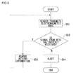
- Fig. 5 shows how damage to the glass sheet 18 is detected by the glass panel damage detection system 12.
- the reader 14 transmits an electromagnetic wave to the RFID tag 20 (S51). Subsequently, the RFID tag 20 receives the electromagnetic wave of S51 and responds to the wave by transmitting to the reader 14 a signal containing information stored in the ID chip 24 (S52).
- S51 the RFID tag 20
- S52 the electromagnetic wave of S51
- S52 the signal containing information stored in the ID chip 24
- the reader 14 receives the signal transmitted from the RFID tag 20 and obtains the identification information stored in the ID chip 24 (S53). However, failure occurs in obtaining the identification information stored in the ID chip 24 unless the ID chip 24 properly receives a signal.
- the reader 14 transmits an electromagnetic wave again to the RFID tag 20 (S51).
- the interval for transmission of the electromagnetic wave is appropriately set.
- the alarm device 16 alerts of the failure (S54).
- tempered glass once partially damaged, will have a network of cracks on the entirety of the surface thereof. This will cause at least a part of the antenna 22 to be damaged, preventing the ID chip 24 from properly providing the identification information wirelessly via the antenna 22. As a result, the reader 14 fails to obtain the identification information from the ID chip 24 properly. Accordingly, when the reader 14 fails to obtain the identification information properly in response to a request from the reader 14 to the ID chip 24, it is possible to determine that the tempered glass of the glass panel 10 is broken.
- a glass panel 70 according to the second embodiment A description will now be given, by referring to Fig. 6, of a glass panel 70 according to the second embodiment. The description of those aspects of the second embodiment that are identical to the corresponding aspects of the first embodiment will be omitted. Those components identical with or corresponding to components of the glass panel 10 according to the first embodiment are designated by the same reference numerals. In describing the second embodiment, it will be assumed that the glass panel 70 is used as an insulating glass unit sash of a house.
- Fig. 6 shows the cross section of the glass panel 70.
- the glass panel 70 comprises: a first glass sheet 62 facing the outside and formed of tempered glass; a second glass sheet 64 facing the inside; an anchoring frame 74 for securing the first glass sheet 62 and the second glass sheet 64 so as to be parallel and opposite to each other so that an air gap layer72 is formed between the first glass sheet 62 and the second glass sheet 64; and an RFID tag 20 provided on the first glass sheet 62 so as to face the air gap layer 72.
- the RFID tag 20 is provided with an antenna 22 and an ID chip 24.
- the antenna 22 is provided on the surface of the first glass sheet 62 so as to face the air gap layer 72.
- Argon gas, helium gas or high vacuum gas is sealed in the air gap layer 72 so that heat insulation between the first glass sheet 62 and the second glass sheet 64 is improved.
- the glass panel 70 is provided with a spacer 76 sandwiched between the first glass sheet 62 and the second glass sheet 64 and hermetically sealing the gas in the air gap layer 72.
- the RFID tag 20 receives an electromagnetic wave at certain intervals (e.g., at intervals of one minute) from the reader 14 located inside the building. In response to a request from the reader 14, the RFID tag 20 sends a signal including the identification information stored in the ID chip 24.
- the reader 14 fails to obtain identification information from the RFID tag 20 properly, enabling the detection of the destruction of the first glass sheet 62.
- the antenna 22 is provided on the surface of the first glass sheet 62 so as to face the air gap layer 72.
- the antenna 22 may be provided on the first glass sheet 62 so as to face the outside.
- the second glass sheet 64 may be formed of tempered glass.
- the antenna 22 may be provided on the second glass sheet 64 so as to face the air gap layer 72 or to face the outside.
- the antenna 22 is provided on the surface of the first glass sheet 62 so as to face the air gap layer 72, or on the surface of the second glass sheet 64 so as to face the air gap layer 72 or to face the inside.
- the first glass sheet 62 may not be formed of tempered glass.
- the second glass sheet 64 may be formed of tempered glass so that destruction of the second glass sheet 64 is detected by the RFID tag 20 and the reader 14 when the beast in the animal enclosure attempts to get outside by breaking the insulating glass unit.
- an operation to capture the beast can be initiated immediately by configuring the alarm device 16 to alert the control center of the zoo of the destruction of the second glass sheet 64.
- the first glass sheet 62 may also be formed of tempered glass, and the RFID tag 20 may be formed on the surface of the first glass sheet 62 so as to face the air gap layer 72 or to face the outside.
- first glass sheet 62 and the second glass sheet 64 are arranged substantially parallel with each other.
- the interval between the first glass sheet 62 and the second glass sheet 64 may be such that the interval is relatively small toward the top or bottom thereof.
- one of the first glass sheet 62 and the second glass sheet 64 may be smaller in width than the other.
- the RFID tag 20 of the glass panel 10 and the glass panel 70 of the embodiments is of passive type.
- the RFID tag may be of active type such that a solar cell is attached on the surface of the glass sheet and the ID chip 24 is connected to the solar cell.
- the glass panel 10 and the glass panel 70 according to the embodiments may be used to constitute an insulating glass unit (e.g., a three-layer glass).
- an insulating glass unit e.g., a three-layer glass.
Landscapes
- Physics & Mathematics (AREA)
- General Physics & Mathematics (AREA)
- Burglar Alarm Systems (AREA)
- Joining Of Glass To Other Materials (AREA)
Applications Claiming Priority (2)
| Application Number | Priority Date | Filing Date | Title |
|---|---|---|---|
| JP2004381907A JP2006188823A (ja) | 2004-12-28 | 2004-12-28 | ガラスパネルおよびガラスパネル破損検知システム |
| PCT/JP2005/019930 WO2006070530A1 (fr) | 2004-12-28 | 2005-10-28 | Panneau de verre et systeme de detection de rupture du panneau de verre |
Publications (2)
| Publication Number | Publication Date |
|---|---|
| EP1833030A1 true EP1833030A1 (fr) | 2007-09-12 |
| EP1833030A4 EP1833030A4 (fr) | 2009-04-08 |
Family
ID=36614656
Family Applications (1)
| Application Number | Title | Priority Date | Filing Date |
|---|---|---|---|
| EP05805215A Withdrawn EP1833030A4 (fr) | 2004-12-28 | 2005-10-28 | Panneau de verre et systeme de detection de rupture du panneau de verre |
Country Status (5)
| Country | Link |
|---|---|
| US (1) | US20080129499A1 (fr) |
| EP (1) | EP1833030A4 (fr) |
| JP (1) | JP2006188823A (fr) |
| CN (1) | CN101095174A (fr) |
| WO (1) | WO2006070530A1 (fr) |
Cited By (3)
| Publication number | Priority date | Publication date | Assignee | Title |
|---|---|---|---|---|
| FR3055497A1 (fr) * | 2016-08-29 | 2018-03-02 | Saint-Gobain Glass France | Systeme et procede de maintenance d'au moins un vitrage |
| EP3127096A4 (fr) * | 2014-03-31 | 2018-03-21 | Glass Security Pte Ltd | Dispositif de détection de détérioration et procédé d'installation dudit dispositif |
| WO2020157252A1 (fr) * | 2019-01-31 | 2020-08-06 | Agc Glass Europe | Vitrage isolant avec unité d'antenne |
Families Citing this family (15)
| Publication number | Priority date | Publication date | Assignee | Title |
|---|---|---|---|---|
| JP4735631B2 (ja) * | 2007-09-28 | 2011-07-27 | 株式会社豊田自動織機 | 開閉式ウィンドウガラスの破損検出装置 |
| CN102055062A (zh) * | 2009-10-29 | 2011-05-11 | 深圳富泰宏精密工业有限公司 | 电子装置壳体及其制作方法 |
| US9081409B2 (en) | 2011-01-21 | 2015-07-14 | The United States Of America As Represented By The Secretary Of The Navy | Event detection control system for operating a remote sensor or projectile system |
| CN105975884A (zh) * | 2016-05-04 | 2016-09-28 | 上海善继能科技有限公司 | 一种检测玻璃破碎的系统及方法 |
| KR20190037281A (ko) * | 2016-08-02 | 2019-04-05 | 쌩-고벵 글래스 프랑스 | 경보 판유리 조립체 |
| CN108226231A (zh) * | 2018-01-29 | 2018-06-29 | 英华达(上海)科技有限公司 | 缺陷评估系统 |
| PL3794200T3 (pl) * | 2018-05-14 | 2022-08-29 | Saint-Gobain Glass France | Jednostka oszklenia izolacyjnego |
| PL3794198T3 (pl) * | 2018-05-14 | 2022-08-01 | Saint-Gobain Glass France | Jednostka oszklenia izolacyjnego |
| WO2019219460A1 (fr) * | 2018-05-14 | 2019-11-21 | Saint-Gobain Glass France | Ensemble vitrage isolant |
| EP3918172B1 (fr) * | 2019-01-29 | 2023-01-11 | Saint-Gobain Glass France | Unité de vitrage isolant et vitrage |
| CN110534868B (zh) * | 2019-08-09 | 2021-12-28 | 福耀玻璃工业集团股份有限公司 | 车窗玻璃及其制备方法、车辆 |
| US20230066134A1 (en) * | 2020-02-14 | 2023-03-02 | Saint-Gobain Glass France | Insulating glass pane arrangement with integrated component |
| CA3179029A1 (fr) * | 2020-09-14 | 2022-03-17 | Christian EFFERTZ | Vitrage isolant et vitrage |
| CA3180277A1 (fr) * | 2020-09-23 | 2022-03-31 | Thomas HOLTSTIEGE | Vitrage isolant et vitrage |
| CN113605816B (zh) * | 2020-12-25 | 2022-09-23 | 中力玻璃有限公司 | 一种具有防盗警报功能的low-e玻璃及其制造方法 |
Family Cites Families (15)
| Publication number | Priority date | Publication date | Assignee | Title |
|---|---|---|---|---|
| JPS55162194A (en) * | 1979-05-31 | 1980-12-17 | Omron Tateisi Electronics Co | Method of detecting scratches of tempered glass |
| JPS62118494A (ja) * | 1985-11-19 | 1987-05-29 | ホーチキ株式会社 | 防犯装置 |
| JPH0546532Y2 (fr) * | 1986-05-23 | 1993-12-06 | ||
| JPH02232797A (ja) * | 1989-03-07 | 1990-09-14 | Fujitsu Ten Ltd | ガラスの破壊検出装置 |
| JPH0348392A (ja) * | 1989-07-14 | 1991-03-01 | Central Glass Co Ltd | ガラスの破損検出装置 |
| DE4105632C2 (de) * | 1990-11-30 | 1993-12-02 | Hirschmann Richard Gmbh Co | Einbruchmelderanordnung |
| US5627509A (en) * | 1994-08-29 | 1997-05-06 | Ford Motor Company | Glazing unit security system |
| US6121880A (en) * | 1999-05-27 | 2000-09-19 | Intermec Ip Corp. | Sticker transponder for use on glass surface |
| JP2002163732A (ja) * | 2000-11-24 | 2002-06-07 | Takashi Takeda | 防犯機能を有するガラスとガラス戸及びその製法 |
| JP2004334445A (ja) * | 2003-05-06 | 2004-11-25 | Secom Co Ltd | セキュリティガラス及びガラス破壊検知装置 |
| JP2005115409A (ja) * | 2003-10-02 | 2005-04-28 | Inax Corp | 開閉構造物の異常検知装置 |
| DE10354350B4 (de) * | 2003-11-20 | 2006-02-02 | Schollglas Holding- und Geschäftsführungsgesellschaft mbH | Alarmglasscheibeneinheit |
| JP2005301755A (ja) * | 2004-04-13 | 2005-10-27 | Trinity Security Systems Inc | 異常監視装置 |
| US7069160B2 (en) * | 2004-08-31 | 2006-06-27 | Cecil Kenneth B | Intrusion detection system and method thereof |
| US20060127611A1 (en) * | 2004-12-13 | 2006-06-15 | Chip Hunter | Architectural glass panel |
-
2004
- 2004-12-28 JP JP2004381907A patent/JP2006188823A/ja active Pending
-
2005
- 2005-10-28 WO PCT/JP2005/019930 patent/WO2006070530A1/fr not_active Ceased
- 2005-10-28 US US11/794,340 patent/US20080129499A1/en not_active Abandoned
- 2005-10-28 CN CN200580045267.1A patent/CN101095174A/zh active Pending
- 2005-10-28 EP EP05805215A patent/EP1833030A4/fr not_active Withdrawn
Cited By (6)
| Publication number | Priority date | Publication date | Assignee | Title |
|---|---|---|---|---|
| EP3127096A4 (fr) * | 2014-03-31 | 2018-03-21 | Glass Security Pte Ltd | Dispositif de détection de détérioration et procédé d'installation dudit dispositif |
| US9978229B2 (en) | 2014-03-31 | 2018-05-22 | Glass Security Pte Ltd | Tamper detection device and a method for installing the device |
| FR3055497A1 (fr) * | 2016-08-29 | 2018-03-02 | Saint-Gobain Glass France | Systeme et procede de maintenance d'au moins un vitrage |
| WO2018042102A1 (fr) * | 2016-08-29 | 2018-03-08 | Saint-Gobain Glass France | Systeme et procede de maintenance d'au moins un vitrage |
| WO2020157252A1 (fr) * | 2019-01-31 | 2020-08-06 | Agc Glass Europe | Vitrage isolant avec unité d'antenne |
| US12374775B2 (en) | 2019-01-31 | 2025-07-29 | Agc Glass Europe | Insulating glazing unit with antenna unit |
Also Published As
| Publication number | Publication date |
|---|---|
| WO2006070530A1 (fr) | 2006-07-06 |
| EP1833030A4 (fr) | 2009-04-08 |
| US20080129499A1 (en) | 2008-06-05 |
| JP2006188823A (ja) | 2006-07-20 |
| CN101095174A (zh) | 2007-12-26 |
Similar Documents
| Publication | Publication Date | Title |
|---|---|---|
| US20080129499A1 (en) | Glass Panel and Glass Panel Breakage Detection System | |
| US7218217B2 (en) | False alarm reduction in security systems using weather sensor and control panel logic | |
| US6104285A (en) | Anti-theft security system and a process for the automatic detection and identification of merchandise security labels | |
| US5892442A (en) | Two-way pager alarm system | |
| US7081815B2 (en) | Radio frequency security system, method for a building facility or the like, and apparatus and methods for remotely monitoring the status of fire extinguishers | |
| US7859404B2 (en) | Method and apparatus for proximity activated RFID system | |
| US8400276B2 (en) | Monitoring system, terminal device and main control device thereof, and method and program for registering terminal device | |
| US5386209A (en) | Cluster alarm monitoring system | |
| US9728072B2 (en) | Method for detecting, recognizing, and automatic disarming of an alarm control unit, and alarm system suitable for its use | |
| US6646550B1 (en) | Radio frequency security system and method for a building facility | |
| CN102483877A (zh) | 控制和监控方法 | |
| JP2006163659A (ja) | 侵入検知システム | |
| JP2005115409A (ja) | 開閉構造物の異常検知装置 | |
| JP4162543B2 (ja) | 硝子の破壊検出装置 | |
| JP2005031831A (ja) | 工事現場防犯システム | |
| JP2006031409A (ja) | 家屋侵入防止アラーム発生システム装置 | |
| JP2004334445A (ja) | セキュリティガラス及びガラス破壊検知装置 | |
| JP2001307238A (ja) | 防犯システム及び切削音検出方法 | |
| US9798966B2 (en) | Systems and methods of smart card based mobile pull stations | |
| KR200332862Y1 (ko) | 사용자 단말기를 이용한 사무실 원격감시장치 | |
| CN215769731U (zh) | 一种rfid检测装置及rfid读写器的检测系统 | |
| JP2005322008A (ja) | 侵入者監視システム及び侵入者監視方法 | |
| JP2003006753A (ja) | マイクロ波侵入検出装置 | |
| EP1313076A2 (fr) | Dispositif de sécurité et système d'alarme d'intrusion | |
| KR20100048823A (ko) | 터미널형 유/무선 다기능 감지 장치 |
Legal Events
| Date | Code | Title | Description |
|---|---|---|---|
| PUAI | Public reference made under article 153(3) epc to a published international application that has entered the european phase |
Free format text: ORIGINAL CODE: 0009012 |
|
| 17P | Request for examination filed |
Effective date: 20070705 |
|
| AK | Designated contracting states |
Kind code of ref document: A1 Designated state(s): DE FR GB |
|
| DAX | Request for extension of the european patent (deleted) | ||
| RBV | Designated contracting states (corrected) |
Designated state(s): DE FR GB |
|
| A4 | Supplementary search report drawn up and despatched |
Effective date: 20090311 |
|
| STAA | Information on the status of an ep patent application or granted ep patent |
Free format text: STATUS: THE APPLICATION IS DEEMED TO BE WITHDRAWN |
|
| 18D | Application deemed to be withdrawn |
Effective date: 20090609 |