EP1833033B1 - Onduleur de voltage surveillé pour système de sécurité - Google Patents
Onduleur de voltage surveillé pour système de sécurité Download PDFInfo
- Publication number
- EP1833033B1 EP1833033B1 EP07103570A EP07103570A EP1833033B1 EP 1833033 B1 EP1833033 B1 EP 1833033B1 EP 07103570 A EP07103570 A EP 07103570A EP 07103570 A EP07103570 A EP 07103570A EP 1833033 B1 EP1833033 B1 EP 1833033B1
- Authority
- EP
- European Patent Office
- Prior art keywords
- security system
- power
- control panel
- power source
- power supply
- Prior art date
- Legal status (The legal status is an assumption and is not a legal conclusion. Google has not performed a legal analysis and makes no representation as to the accuracy of the status listed.)
- Not-in-force
Links
Images

Classifications
-
- G—PHYSICS
- G08—SIGNALLING
- G08B—SIGNALLING SYSTEMS, e.g. PERSONAL CALLING SYSTEMS; ORDER TELEGRAPHS; ALARM SYSTEMS
- G08B29/00—Checking or monitoring of signalling or alarm systems; Prevention or correction of operating errors, e.g. preventing unauthorised operation
- G08B29/18—Prevention or correction of operating errors
- G08B29/181—Prevention or correction of operating errors due to failing power supply
-
- G—PHYSICS
- G08—SIGNALLING
- G08B—SIGNALLING SYSTEMS, e.g. PERSONAL CALLING SYSTEMS; ORDER TELEGRAPHS; ALARM SYSTEMS
- G08B25/00—Alarm systems in which the location of the alarm condition is signalled to a central station, e.g. fire or police telegraphic systems
- G08B25/01—Alarm systems in which the location of the alarm condition is signalled to a central station, e.g. fire or police telegraphic systems characterised by the transmission medium
- G08B25/08—Alarm systems in which the location of the alarm condition is signalled to a central station, e.g. fire or police telegraphic systems characterised by the transmission medium using communication transmission lines
-
- H—ELECTRICITY
- H02—GENERATION; CONVERSION OR DISTRIBUTION OF ELECTRIC POWER
- H02J—ELECTRIC POWER NETWORKS; CIRCUIT ARRANGEMENTS OR SYSTEMS FOR SUPPLYING OR DISTRIBUTING ELECTRIC POWER; SYSTEMS FOR STORING ELECTRIC ENERGY
- H02J9/00—Circuit arrangements for emergency or stand-by power supply, e.g. for emergency lighting
- H02J9/04—Circuit arrangements for emergency or stand-by power supply, e.g. for emergency lighting in which the distribution system is disconnected from the normal source and connected to a standby source
- H02J9/06—Circuit arrangements for emergency or stand-by power supply, e.g. for emergency lighting in which the distribution system is disconnected from the normal source and connected to a standby source with automatic change-over, e.g. UPS systems
- H02J9/062—Circuit arrangements for emergency or stand-by power supply, e.g. for emergency lighting in which the distribution system is disconnected from the normal source and connected to a standby source with automatic change-over, e.g. UPS systems for AC powered loads
Definitions
- the invention relates to residential and commercial security systems, and more particularly to a voltage inverter for a security system.
- Modern residential and commercial security systems may be connected to a central monitoring station via the internet or an intranet.
- the central monitoring station provides, among other things, for updates and upkeep of the security system. Additionally, the central monitoring station may have security personnel who are trained to handle facility emergencies or alarms. As such, the connection to the central monitoring station is crucial for the proper operation of the security system.
- connections between the security system and the central monitoring station may be via external switches, routers and modulator/demodulator (modem).
- modem modulator/demodulator
- the connection from the control panel 110 to central monitoring station 170 may be through the Internet 195 or through some proprietary network connection.
- the external switches, routers and modulator/demodulator and other components rely on AC power sources to properly operate.
- control panel of the security systems may be powered by AC power sources backed up by a battery.
- the battery provides for back-up in those cases where the regular AC power source is interrupted due to outage or intentional sabotage. Generally, a battery back-up will provide approximately 24 hours of back-up power for the components of the control panel.
- a potential solution is to provide battery back-up for every network component device so that the network component device is operable even when the AC power supply is interrupted.
- the additional circuitry needed for individual battery back-up for each component device can make this solution costly.
- the bulk added to each network component device would make placing the network component devices unwieldy.
- the task of checking and maintaining each battery back-up would be cost prohibitive.
- independent battery back-up does not allow faults or trouble conidtions to be detected and reported by the security system.
- the invention allows low-cost commercially available network components to be used in the system.
- US-A-2003/190906 discloses a security system which receives its primary power from an A/C power line, and includes a back-up battery for continued operation during power outages. Another security system with a back-up battery is described in US-A-6366211 .
- the present invention provides a monitored voltage inverter for a security system.
- a voltage inverter is coupled to the power supply of the control panel which can provide AC power to the network hardware devices.
- the voltage inverter converts the DC voltage of a back-up power supply to household or commercial AC current.
- the voltage inverter is mounted on the printed circuit board and is coupled to the network hardware devices.
- the invention is defined by a security system according to claim 1 and a method according to claim 9.
- Security system 100 includes a control panel 110 which may use proprietary buses and separate wiring and cables within a building to communicate with a variety of sensors 125 and 127.
- the sensors 125, 127 may be, for example, radio frequency motion sensors, cameras, alarm reporting devices, or the like, which generally report intrusions or emergencies in the building to the control panel.
- the control panel 110 typically houses the electronics of the control panel on a printed circuit board 150.
- the printed circuit board 150 may contain electronic components for prioritizing and maintaining sensor inputs to the security system and various detection and reporting components for reporting conditions to the central monitoring station.
- the printed circuit board includes a power supply 140 for regulating the power delivered to components on the printed circuit board and to sensors 125 and 127,
- Electrical power/current is provided to networking hardware devices over electrical wiring/cables to the printed circuit board and to network switches and routers 180 and 190.
- Residential buildings and commercial establishments may, as a matter of convenience, provide electrical power to the networking hardware devices by using the electrical power available at the premises.
- the same electrical power 120 is provided to Ethernet hub 180 for facilitating communication to the central monitoring station 170 via the Internet 195 or some other communication network.
- the same source of electrical power 120 may be provided to the network hub/switch 180 for modulating and demodulating data transmitted to or received from the central monitoring station 170.
- the security system may include a back-up communication equipment 160 for providing communication to the central monitoring station 170 when the primary communication is unavailable.
- Such back-up communication equipment 160 may be a GSM dialer configured to communicate wirelessly to the central monitoring station.
- Such back-up communication equipment 160 may be a telephone modem configured for communicating with the central monitoring station 170 through plain old telephone service (POTS) lines.
- POTS plain old telephone service
- the back-up communication equipment 160 is illustrated as a separate component, it may be integrated within the printed circuit board 150 or the control panel 110. The back-up communication equipment 160 is powered by the same electrical power 120.
- the control panel and sensors are powered by a power supply 140 which regulates the voltage and current to prevent overloading or spikes in the voltage.
- the power supply additionally monitors the AC power source 120 for interruptions, and switches to the back-up power supply 130 in those cases.
- the back-up power supply 130 is illustrated as a rechargeable lead acid battery providing DC power to the control panel and the sensors. It will be understood that the back-up power supply may be an uninterruptible power supply (UPS) which may be comprised of a lead-acid battery, generator, a metal fuel cell or any other isolated power source. In any case, the back-up power supply may have the capacity to provide power to the control panel and sensors for a short period of time, typically on the order of 24 hours.
- UPS uninterruptible power supply
- the illustrated security system 100 may, however, experience problems if the AC power supply is interrupted. Since the network hardware devices are powered by the same AC power supply, any interruption in the AC power supply will render the network hardware devices 180 and 190 inoperable. Additionally, back-up communication equipment 160 may also be rendered inoperable since the AC power supply supplies the power to the equipment.
- the present invention proposes a voltage inverter coupled to the power supply of the control panel which can provide AC power to the network hardware devices.
- the voltage inverter converts the DC voltage of the back-up power supply to household or commercial AC current.
- the voltage inverter is mounted on the printed circuit board and is coupled to the network hardware devices.
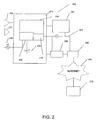
- Security system 200 includes the control panel 210 which may use proprietary buses and separate wiring and cables within a building to communicate with a variety of sensors 225 and 227.
- the sensors 225, 227 may be, for example, radio frequency motion sensors, cameras, alarm reporting devices, or the like, which generally report intrusions or emergencies in the building to the control panel.
- the sensors are coupled to Ethernet lines and are powered by the Ethernet line. So-called power over Ethernet sensors can ease the power wiring requirements since the sensors are powered over the Ethernet connections.
- the control panel 210 typically houses the electronics of the control panel on a printed circuit board 250.
- the printed circuit board 250 may contain electronic components for prioritizing and maintaining sensor inputs to the security system and detection and reporting components for reporting conditions to the central monitoring station.
- the printed circuit board includes a power supply 240 for regulating the power delivered to components on the printed circuit board and to sensors 225 and 127.
- a voltage inverter 215 is shown as residing on the printed circuit board 250.
- the voltage inverter converts DC power to AC power/current.
- Electrical power/current is provided to networking hardware devices over electrical wiring/cables 224 to the printed circuit board and to network switches and routers 280 and 290.
- the security system may include a back-up communication equipment 260 for providing communication to the central monitoring station 270 when the primary communication is unavailable.
- Such back-up communication equipment 260 may be a GSM dialer configured to communicate wirelessly to the central monitoring station.
- the back-up communication equipment 260 may be a telephone modem configured for communicating with the central monitoring station 270 through plain old telephone service (POTS) lines.
- POTS plain old telephone service
- the control panel and sensors are powered by a power supply 240 which regulates the voltage and current to prevent overloading or spikes in the voltage.
- the power supply additionally monitors the AC power source 220 for interruptions, and switches to the back-up power supply 230 in those cases.
- the back-up power supply 230 is illustrated as a rechargeable lead acid battery providing DC power to the control panel and the sensors. It will be understood that the back-up power supply may be an uninterruptible power supply (UPS) which may be comprised of a lead-acid battery, generator, or a metal fuel cell. In any case, the back-up power supply may have the capacity to provide power to the control panel and sensors for a short period of time.
- UPS uninterruptible power supply
- the security system 200 of FIG. 2 utilizes the voltage inverter for providing a constant power supply for the network hardware devices.
- Voltage inverters are well known circuits which convert a DC voltage input to an AC voltage output.
- the battery voltage in the panel is 12 (or 24) VDC, and required AC voltage depends on geographic location (120V/60Hz in North America).
- This invention uses the battery voltage and other I/O between the control panel and voltage inverter to provide an intelligent, monitored, battery backed-up power supply for external AC powered devices.
- the voltage inverter monitors the power/current from the power source 220. When the power source is interrupted, the voltage inverter converts the DC voltage from the back-up battery to AC power/current for the network hardware devices. Otherwise, during normal operation, the voltage inverter acts as a pass-through device allowing AC power to the network hardware devices. In an alternative embodiment, the voltage inverter may always supply power to the network devices to avoid possible switching glitches when AC power is lost.
Landscapes
- Engineering & Computer Science (AREA)
- Physics & Mathematics (AREA)
- General Physics & Mathematics (AREA)
- Business, Economics & Management (AREA)
- Emergency Management (AREA)
- Computer Security & Cryptography (AREA)
- Power Engineering (AREA)
- Stand-By Power Supply Arrangements (AREA)
- Alarm Systems (AREA)
- Power Conversion In General (AREA)
Claims (13)
- Système de sécurité comprenant :un panneau de commande (110) ;des capteurs (225, 227) couplés électriquement audit panneau de commande (110) ; etune alimentation (240) pour alimenter en courant ledit panneau de commande (110), ladite alimentation étant couplée à une source d'alimentation en c.a. (220) et à une source d'alimentation de secours en c.c. (230) ; et caractérisé en ce que ce système comprend en outré :un dispositif matériel de réseau alimenté en c.a. (280, 290) couplé audit panneau de commande pour transmettre et recevoir des données ; etun onduleur de tension (215) en série avec ladite alimentation, ledit onduleur de tension étant configuré de façon à alimenter ledit dispositif matériel de réseau (280, 290) à partir de la source d'alimentation de secours en c.c. (230).
- Système de sécurité selon la revendication 1, dans lequel ladite source d'alimentation de secours en c.c. (230) est une batterie.
- Système de sécurité selon la revendication 2, dans lequel ladite batterie est une batterie au plomb.
- Système de sécurité selon la revendication 1, dans lequel ladite source d'alimentation de secours en c.c. (230) est une pile à combustible.
- Système de sécurité selon l'une quelconque des revendications précédentes, dans lequel ledit capteur (225, 227) est soit un capteur de mouvement, soit un capteur de radiofréquence, soit un capteur d'intrusion.
- Système de sécurité selon l'une quelconque des revendications précédentes, dans lequel ledit dispositif matériel de réseau alimenté en c.a. (280, 290) est soit un concentrateur, soit un commutateur, soit un routeur, soit un modem.
- Système de sécurité selon l'une quelconque des revendications précédentes, comprenant en outre:un dispositif de communication de secours (160) couplé audit panneau de commande (110), ledit onduleur de tension étant configuré de façon à alimenter ledit dispositif de communication de secours.
- Système de sécurité selon la revendication 7, dans lequel ledit dispositif de communication de secours (160) est soit un composeur GSM, soit un modem téléphonique.
- Procédé pour fournir une alimentation à un système de sécurité, ledit système de sécurité comprenant un panneau de commande (110) ; des capteurs (225, 227) couplés électriquement audit panneau de commande ; une alimentation (240) pour alimenter en courant ledit panneau de commande (110), ladite alimentation étant couplée à une source d'alimentation en c.a. (220) et à une source d'alimentation de secours en c.c. (230) ; un dispositif matériel de réseau alimenté en c.a. (280, 290) couplé audit panneau de commande pour transmettre et recevoir des données ; et un onduleur de tension (215) en série avec ladite alimentation, ledit procédé comprenant les étapes consistant à :surveiller ladite source d'alimentation en c.a. (220) au niveau de l'onduleur de tension ;fournir une alimentation en c.a. audit panneau de commande (110) et audit dispositif matériel de réseau alimenté en c.a. (280, 290) si ladite source d'alimentation en c.a. est fonctionnelle; etsi ladite source d'alimentation en c.a. (220) est interrompue, convertir l'alimentation en c.c. venant de ladite source de secours (230) en une alimentation en c.a. et fournir ladite alimentation en c.a. audit dispositif matériel de réseau (280, 290).
- Procédé la revendication 9, dans lequel ladite source d'alimentation de secours en c.c. (230) est une batterie.
- Procédé selon la revendication 10, dans lequel ladite batterie est une batterie au plomb.
- Procédé selon l'une quelconque des revendications 9 à 11, dans lequel ladite source d'alimentation de secours en c.c. (230) est une pile à combustible.
- Procédé selon l'une quelconque des revendications 9 à 12, dans lequel ledit dispositif matériel de réseau alimenté en c.a. (280, 290) est soit un concentrateur, soit un commutateur, soit un routeur, soit un modem.
Applications Claiming Priority (1)
| Application Number | Priority Date | Filing Date | Title |
|---|---|---|---|
| US11/373,637 US7446654B2 (en) | 2006-03-09 | 2006-03-09 | Monitored voltage inverter for security system |
Publications (3)
| Publication Number | Publication Date |
|---|---|
| EP1833033A2 EP1833033A2 (fr) | 2007-09-12 |
| EP1833033A3 EP1833033A3 (fr) | 2008-04-30 |
| EP1833033B1 true EP1833033B1 (fr) | 2010-08-11 |
Family
ID=38080993
Family Applications (1)
| Application Number | Title | Priority Date | Filing Date |
|---|---|---|---|
| EP07103570A Not-in-force EP1833033B1 (fr) | 2006-03-09 | 2007-03-06 | Onduleur de voltage surveillé pour système de sécurité |
Country Status (6)
| Country | Link |
|---|---|
| US (1) | US7446654B2 (fr) |
| EP (1) | EP1833033B1 (fr) |
| CN (1) | CN101056007B (fr) |
| CA (1) | CA2580310C (fr) |
| DE (1) | DE602007008307D1 (fr) |
| ES (1) | ES2348051T3 (fr) |
Families Citing this family (7)
| Publication number | Priority date | Publication date | Assignee | Title |
|---|---|---|---|---|
| WO2011116258A1 (fr) | 2010-03-19 | 2011-09-22 | Videolarm, Inc. | Système de priorisation d'alimentation électrique par câble ethernet et procédé pour des caméras de surveillance |
| US8566651B2 (en) | 2010-11-15 | 2013-10-22 | LifeSafety Power Inc. | Apparatus and method for a networked power management system for security and life safety applications |
| US9098390B2 (en) | 2010-11-15 | 2015-08-04 | Lifesafety Power, Inc. | Apparatus and method for a networked power management system with one-click remote battery discharge testing |
| US9952565B2 (en) | 2010-11-15 | 2018-04-24 | Guang Liu | Networked, channelized power distribution, monitor and control for security and life safety applications |
| US9959720B2 (en) * | 2016-01-21 | 2018-05-01 | Cezary Jan Jaronczyk | Input zone enhancer and method |
| US11183042B2 (en) | 2019-07-19 | 2021-11-23 | Honeywell International Inc. | Thermographic detector device for a fire alarm control system |
| CN112713530A (zh) * | 2021-01-29 | 2021-04-27 | 国网河南省电力公司邓州市供电公司 | 一种用于安全操作的智能配电柜 |
Family Cites Families (8)
| Publication number | Priority date | Publication date | Assignee | Title |
|---|---|---|---|---|
| US5999094A (en) * | 1986-10-22 | 1999-12-07 | Nilssen; Ole K. | Combination telephone and smoke alarm system |
| CA2165384C (fr) * | 1995-12-15 | 2008-04-01 | Andre Gagnon | Systeme de detection d'intrusions a ligne de transmission ouverte utilisant l'analyse spectrale |
| US5705982A (en) * | 1996-08-01 | 1998-01-06 | North America Technitron Corporation | Intrusion detection, register and indication apparatus |
| US6366211B1 (en) * | 2000-05-15 | 2002-04-02 | Digital Security Controls Ltd. | Remote recovery arrangement for alarm system |
| US6999562B2 (en) * | 2002-04-09 | 2006-02-14 | Honeywell International Inc. | Security control and communication system and method |
| CN2548349Y (zh) * | 2002-04-19 | 2003-04-30 | 中国石油天然气股份有限公司 | 机泵监视器多路冗余电源 |
| US20050206241A1 (en) * | 2004-03-17 | 2005-09-22 | Piyush Saxena | Web-enabled UPS |
| US8471910B2 (en) * | 2005-08-11 | 2013-06-25 | Sightlogix, Inc. | Methods and apparatus for providing fault tolerance in a surveillance system |
-
2006
- 2006-03-09 US US11/373,637 patent/US7446654B2/en active Active
-
2007
- 2007-03-05 CA CA2580310A patent/CA2580310C/fr not_active Expired - Fee Related
- 2007-03-06 ES ES07103570T patent/ES2348051T3/es active Active
- 2007-03-06 EP EP07103570A patent/EP1833033B1/fr not_active Not-in-force
- 2007-03-06 DE DE602007008307T patent/DE602007008307D1/de active Active
- 2007-03-09 CN CN2007100862696A patent/CN101056007B/zh not_active Expired - Fee Related
Also Published As
| Publication number | Publication date |
|---|---|
| US20070210915A1 (en) | 2007-09-13 |
| EP1833033A2 (fr) | 2007-09-12 |
| US7446654B2 (en) | 2008-11-04 |
| CN101056007A (zh) | 2007-10-17 |
| EP1833033A3 (fr) | 2008-04-30 |
| ES2348051T3 (es) | 2010-11-29 |
| CN101056007B (zh) | 2010-10-13 |
| CA2580310A1 (fr) | 2007-09-09 |
| CA2580310C (fr) | 2015-06-16 |
| DE602007008307D1 (de) | 2010-09-23 |
Similar Documents
| Publication | Publication Date | Title |
|---|---|---|
| US7081827B2 (en) | Power over Ethernet-prioritized active splitter | |
| EP1833033B1 (fr) | Onduleur de voltage surveillé pour système de sécurité | |
| US20040252421A1 (en) | Miniaturized motor overload protector | |
| JP5166379B2 (ja) | 電力連携システム | |
| CN106104965A (zh) | 用于向以太网供电设备提供不间断电源的系统及方法 | |
| US7872378B2 (en) | Power management system | |
| JP2009153339A (ja) | 直流配電システム | |
| US20250007324A1 (en) | System and Method for Monitoring Power Supply Devices | |
| CN104137383B (zh) | 用于维护电力系统中的适当的相中性布线的系统和方法 | |
| CN109062068A (zh) | 基于无线传输的家电监控系统 | |
| JP2005278267A (ja) | 電流監視装置 | |
| JPH1141818A (ja) | 分散型発電システム | |
| EP4275331B1 (fr) | Concentrateur de communication de local | |
| GB2532999A (en) | Integrated long range ISM sub gigahertz network for monitoring & controlling theft, damage and loss of supply to high voltage cables | |
| JP2004254459A (ja) | 電源ネットワークシステム | |
| JP2009177924A (ja) | 電力供給システム及びそれに用いられるアウトレット | |
| RU2318281C1 (ru) | Автоматизированная система гарантированного электроснабжения стационарного объекта | |
| US10897365B1 (en) | Mid-span automatic transfer switch for power over ethernet lighting and powered devices | |
| JP2000236587A (ja) | 無停電電源装置及びそれを用いた情報通信システム | |
| JP2000048287A (ja) | 侵入検知センサ装置 | |
| RU72806U1 (ru) | Унифицированный сетевой адаптер для удаленного управления агрегатами бесперебойного питания по линиям связи | |
| CN208477317U (zh) | 一种家电故障预警的远程监控系统 | |
| RU64840U1 (ru) | Сетевой адаптер для удаленного управления бесперебойным питанием корпоративных коммуникационных систем | |
| JP2003162460A (ja) | 無停電電源装置の動作状態監視システム | |
| RU73576U1 (ru) | Коммутируемый сетевой адаптер для удаленного управления агрегатами бесперебойного питания по линиям связи |
Legal Events
| Date | Code | Title | Description |
|---|---|---|---|
| PUAI | Public reference made under article 153(3) epc to a published international application that has entered the european phase |
Free format text: ORIGINAL CODE: 0009012 |
|
| 17P | Request for examination filed |
Effective date: 20070326 |
|
| AK | Designated contracting states |
Kind code of ref document: A2 Designated state(s): AT BE BG CH CY CZ DE DK EE ES FI FR GB GR HU IE IS IT LI LT LU LV MC MT NL PL PT RO SE SI SK TR |
|
| AX | Request for extension of the european patent |
Extension state: AL BA HR MK YU |
|
| PUAL | Search report despatched |
Free format text: ORIGINAL CODE: 0009013 |
|
| AK | Designated contracting states |
Kind code of ref document: A3 Designated state(s): AT BE BG CH CY CZ DE DK EE ES FI FR GB GR HU IE IS IT LI LT LU LV MC MT NL PL PT RO SE SI SK TR |
|
| AX | Request for extension of the european patent |
Extension state: AL BA HR MK RS |
|
| AKX | Designation fees paid |
Designated state(s): DE ES FR GB IT |
|
| 17Q | First examination report despatched |
Effective date: 20090113 |
|
| GRAP | Despatch of communication of intention to grant a patent |
Free format text: ORIGINAL CODE: EPIDOSNIGR1 |
|
| GRAS | Grant fee paid |
Free format text: ORIGINAL CODE: EPIDOSNIGR3 |
|
| GRAA | (expected) grant |
Free format text: ORIGINAL CODE: 0009210 |
|
| AK | Designated contracting states |
Kind code of ref document: B1 Designated state(s): DE ES FR GB IT |
|
| REG | Reference to a national code |
Ref country code: GB Ref legal event code: FG4D |
|
| REF | Corresponds to: |
Ref document number: 602007008307 Country of ref document: DE Date of ref document: 20100923 Kind code of ref document: P |
|
| PG25 | Lapsed in a contracting state [announced via postgrant information from national office to epo] |
Ref country code: IT Free format text: LAPSE BECAUSE OF FAILURE TO SUBMIT A TRANSLATION OF THE DESCRIPTION OR TO PAY THE FEE WITHIN THE PRESCRIBED TIME-LIMIT Effective date: 20100811 |
|
| PGFP | Annual fee paid to national office [announced via postgrant information from national office to epo] |
Ref country code: FR Payment date: 20110304 Year of fee payment: 5 |
|
| PLBE | No opposition filed within time limit |
Free format text: ORIGINAL CODE: 0009261 |
|
| STAA | Information on the status of an ep patent application or granted ep patent |
Free format text: STATUS: NO OPPOSITION FILED WITHIN TIME LIMIT |
|
| 26N | No opposition filed |
Effective date: 20110512 |
|
| PGFP | Annual fee paid to national office [announced via postgrant information from national office to epo] |
Ref country code: ES Payment date: 20110325 Year of fee payment: 5 Ref country code: DE Payment date: 20110331 Year of fee payment: 5 Ref country code: GB Payment date: 20110221 Year of fee payment: 5 |
|
| REG | Reference to a national code |
Ref country code: DE Ref legal event code: R097 Ref document number: 602007008307 Country of ref document: DE Effective date: 20110512 |
|
| GBPC | Gb: european patent ceased through non-payment of renewal fee |
Effective date: 20120306 |
|
| REG | Reference to a national code |
Ref country code: FR Ref legal event code: ST Effective date: 20121130 |
|
| REG | Reference to a national code |
Ref country code: DE Ref legal event code: R119 Ref document number: 602007008307 Country of ref document: DE Effective date: 20121002 |
|
| PG25 | Lapsed in a contracting state [announced via postgrant information from national office to epo] |
Ref country code: GB Free format text: LAPSE BECAUSE OF NON-PAYMENT OF DUE FEES Effective date: 20120306 Ref country code: FR Free format text: LAPSE BECAUSE OF NON-PAYMENT OF DUE FEES Effective date: 20120402 |
|
| REG | Reference to a national code |
Ref country code: ES Ref legal event code: FD2A Effective date: 20130716 |
|
| PG25 | Lapsed in a contracting state [announced via postgrant information from national office to epo] |
Ref country code: ES Free format text: LAPSE BECAUSE OF NON-PAYMENT OF DUE FEES Effective date: 20120307 |
|
| PG25 | Lapsed in a contracting state [announced via postgrant information from national office to epo] |
Ref country code: DE Free format text: LAPSE BECAUSE OF NON-PAYMENT OF DUE FEES Effective date: 20121002 |