EP1833625B1 - Dispositif pour deplacer un materiau metallique - Google Patents
Dispositif pour deplacer un materiau metallique Download PDFInfo
- Publication number
- EP1833625B1 EP1833625B1 EP05846059A EP05846059A EP1833625B1 EP 1833625 B1 EP1833625 B1 EP 1833625B1 EP 05846059 A EP05846059 A EP 05846059A EP 05846059 A EP05846059 A EP 05846059A EP 1833625 B1 EP1833625 B1 EP 1833625B1
- Authority
- EP
- European Patent Office
- Prior art keywords
- arm
- arm part
- innermost
- telescopically retractable
- roller table
- Prior art date
- Legal status (The legal status is an assumption and is not a legal conclusion. Google has not performed a legal analysis and makes no representation as to the accuracy of the status listed.)
- Expired - Lifetime
Links
Images

Classifications
-
- B—PERFORMING OPERATIONS; TRANSPORTING
- B21—MECHANICAL METAL-WORKING WITHOUT ESSENTIALLY REMOVING MATERIAL; PUNCHING METAL
- B21B—ROLLING OF METAL
- B21B39/00—Arrangements for moving, supporting, or positioning work, or controlling its movement, combined with or arranged in, or specially adapted for use in connection with, metal-rolling mills
- B21B39/004—Transverse moving
Definitions
- the invention relates to a device for moving metallic material from or onto a conveying device in a direction perpendicular to the conveying direction, wherein the device has a relatively movable to a stationary stand movement arm, in one end region of which at least one gripping element is arranged to grip the metallic Guts wherein the movement arm has at least two arm parts and wherein at least two of the arm parts are telescopically in the manner of a telescope.
- the devices mentioned above are used, which can push the scrap in a horizontal direction transversely to the conveying direction of the roller table on Ablageroste.
- These are, for example, Vorbandabschieber, with which scrap from the rolling line are disposed of by pushing can.
- the duration of the production downtime can be reduced and thus the efficiency of the rolling process can be increased.
- a generic device is from the DE 22 02 848 A known.
- a device provided with a telescopic arm also shows the GB 966,055 A .
- the SU 1766548 A1 discloses a push-off device, with the metallic Good can be moved transversely to the conveying direction of the roller table.
- the estate is thereby moved with a movement arm, which is slidably mounted in a frame; on the movement arm finger-like gripping elements are arranged, which can contact the estate.
- the device builds relatively large in the direction transverse to the conveying direction of the roller table, since the movement arm must be moved over a large width.
- a relatively far projecting movement arm is provided, which is mounted displaceably in a housing transversely to the conveying direction of the roller table.
- the JP 10263624 A suggests a device in which the finger-like gripping elements can be moved down vertically in position as needed. Again, the movement arm protrudes relatively far in the direction transverse to the conveying direction of the roller conveyor.
- the DE-OS 26 00 784 describes the problem of the rapid removal of parts of the pre-strip from the roller conveyor, although details of constructive details of the Vorbandabschiebers are not made.
- the device is suitable both for pushing away scrap material from the roller table and again for pushing the scrap metal on the roller table. Then namely at a later time the scrap can be transported away on the roller table, which has significant economic benefits.
- the invention is therefore the object of a device of the type mentioned in such a way that the mentioned disadvantages are overcome.
- the Abschiebevoriquesen should therefore have a much lower space requirement, without the functionality of the device is adversely affected.
- both a deportation of the scrap material from the roller table as well as, if necessary, a postponement of the goods on the roller table should be possible.
- the solution of this object by the invention is characterized by two gripping elements, one of which is arranged on the innermost, telescopically insertable arm part and one on the arm part, which receives the innermost telescopically insertable arm part directly.
- the movement arm on three arm parts which are telescoped in the manner of a telescope.
- a development provides that the arm parts have a rectangular cross-section basic contour. This achieves high stability, in particular against torsion about the longitudinal axis of the arm.
- At least one of the gripping elements can be rotatably mounted about an axis-The axis is preferably oriented horizontally and points in the conveying direction of the Guts.
- the gripping element arranged on the innermost telescopically insertable arm part is rotatably mounted about said axis; Furthermore, according to this embodiment of the invention arranged on the innermost telescopically insertable arm part directly receiving arm part gripping element is fixedly disposed on this arm part. Furthermore, it can be provided in this solution that arranged on the innermost telescopically insertable arm part gripping element is arranged and pivotable that the innermost telescopically insertable arm part together with gripping element largely, preferably completely, in which the innermost telescopically insertable arm part directly receiving arm can be inserted.
- the device part which is provided for the return of the scrap material from the storage rack on the roller table, in the event that it is not needed, is completely retracted into the arm and so does not constitute an obstacle.
- Another advantage is a hydraulic piston-cylinder system for displacement of the innermost, telescopically insertable Armteil provided relative to the innermost telescopically insertable arm part directly receiving arm.
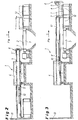
- a conveyor device 3 in the form of a roller conveyor not shown metallic material can be conveyed in the conveying direction F. If there is a fault in the rolling mill and cools preheated rolling stock, which is conveyed via the conveyor 3 to a roller unit, not shown, too strong as a result of the disturbance, it must be disposed of as scrap. In order to remove the scrap material, so that the production process can be resumed after the fault has been eliminated, a storage rack 12 is arranged laterally next to the conveyor device 3.
- the device 1 has a stationary stand 4, which is arranged laterally next to the roller table 3.
- a movement arm 5 is slidably arranged in the direction S.
- a gripping element 7 is arranged in the form of a finger-shaped slide.
- metallic Good 2 are pushed off the roller table 3 on the shelf 12.
- the movement arm 5 is moved relative to the stand 4 by means not shown drive elements to the right. After moving the arm 5, this has the in Fig. 2 partial dot-dash line position.
- the movement arm 5 is designed in several parts.
- it has two arm parts 5 ', 5 ", which can be pushed into one another in the manner of a telescope Fig. 2 2, the two arm parts 5 ', 5 "are shown pushed together in a telescoped manner (it can be seen that there is a relatively small footprint, in the present case through a wall 13) Nevertheless, a large displacement path of the product 2 in the direction S can be realized, as can be seen from the dot-dashed maximum end position of the movement arm 5 (on the right in FIG Fig. 2 ).
- the arm part 5 'provided with the gripping element 7 is, with the estate 2 can be deported from the roller table 3 on the shelf 12.
- another gripping element 8 is provided which is arranged at the end of the innermost arm part 5 " Fig. 3 referenced where the illustrated in maximum extension position movement arm 5 is outlined.
- the gripping element 8 is rotatably mounted about an axis 9, wherein the axis 9 is arranged horizontally and has in the conveying direction F.
- the gripping element 8 in the event that it is not needed, be pivoted in a horizontal position (with dotted lines is in Fig. 3 the pivoting of the gripping element 8 outlined in this position).
- a movement arm 5 arranged in the piston-cylinder system 10 can then the innermost arm part 5 ", ie the innermost telescopic arm, are pulled into this directly receiving arm part 5 'until it is completely absorbed by this.
- Fig. 1 It can be seen that several, in the present case two, devices 1 can be driven by a common drive device 11, ie the displacement movement of the movement arm 5 in the direction S is performed by the drive device 11.
- the movement path of the movement arm 5 or its parts 5 ', 5 can be detected via linear or rotary position encoders (not shown) .
- the movement arms 5 of the individual devices 1 can be coupled electrically, mechanically or hydraulically.
- the device 1 is characterized in that in addition to the deportation of Good 2 from the roller table 3 on the shelf 12 also a pushing back of the grate 12 on the roller table 3 is possible.
- the "retraction arm” 5 is integrated in the" Abschiebearm “5 'If the" retraction arm "5" is not needed, it can be completely submerged in the “Abschiebearm”5'.
- the arm part 5 only extends when scrap material 2 is to be withdrawn from the storage rack 12 onto the roller table 3.
- the finger-like gripping element 8 can be pivoted into the horizontal position (for sinking the arm part 5 "into the arm part 5 ') by means of an actuator (not shown) on the roller table 3 can be provided that this is done by the weight of the gripping element 8, which takes place automatically when the arm 5 "by means of the piston-cylinder system 10 sufficiently from the arm 5 'is pushed out.
- the guide of the arm part 5 can be made by moving rollers, which are arranged on or in the arm part 5 '. Guiding by round rods and sliding bushes or sliding strips is just as possible.
- the scrap belt 2 is withdrawn in a rolling break or a planned furnace gap from the deposit rack 12 on the roller table 3 and fed via the roller table 3 of the scrap processing (in another part of the hall).
- the manual intervention in the danger zone of the roller table 3 is no longer necessary.
- the rolling time can be optimized by means of the device 1, which has an increase in production of the rolling mill result.
Landscapes
- Engineering & Computer Science (AREA)
- Mechanical Engineering (AREA)
- Specific Conveyance Elements (AREA)
- Forging (AREA)
- Manipulator (AREA)
- Forklifts And Lifting Vehicles (AREA)
Claims (9)
- Dispositif pour déplacer un matériau métallique (2) depuis ou vers un dispositif de convoyage (3) dans une direction (S) perpendiculaire à la direction de convoyage (F), ledit dispositif (1) comprenant un bras mobile (5) déplaçable par rapport à un support stationnaire (4), avec au moins un élément de préhension (7, 8) agencé dans une zone terminale (6) du bras pour saisir le matériau métallique (2), ledit bras mobile (5) comprenant au moins deux parties de bras (5', 5"), et au moins deux des parties de bras (5', 5") sont susceptibles d'être rétractées en pénétration l'une dans l'autre de manière télescopique,
caractérisé par
deux éléments de préhension (7, 8), dont l'un est agencé sur la partie de bras (5") la plus intérieure susceptible d'être rétractée de manière télescopique, et dont l'autre est agencé sur la partie de bras (5') qui reçoit directement la partie de bras la plus intérieure (5") susceptible d'être rétractée de manière télescopique. - Dispositif selon la revendication 1,
caractérisé en ce que le bras mobile (5) comprend deux parties de bras (5', 5") qui sont susceptibles d'être rétractées en pénétration l'une dans l'autre de manière télescopique. - Dispositif selon la revendication 1 ou 2,
caractérisé en ce que les parties de bras (5', 5") présentent un contour de base avec une section de forme rectangulaire. - Dispositif selon l'une des revendications 1 à 3,
caractérisé en ce qu'au moins un élément de préhension (8) est monté rotatif autour d'un axe (9). - Dispositif selon la revendication 4,
caractérisé en ce que l'axe est orienté horizontalement et dirigé en direction de convoyage (F). - Dispositif selon l'une des revendications 1 à 5,
caractérisé en ce que l'élément de préhension (8) agencé sur la partie de bras la plus intérieure (5") susceptible d'être rétractée de manière télescopique est monté rotatif autour de l'axe (9), et en ce que l'élément de préhension (8) agencé sur la partie de bras (5') qui reçoit directement la partie de bras la plus intérieure (5") susceptible d'être rétractée de manière télescopique est agencé de manière fixe sur cette partie de bras (5'). - Dispositif selon l'une des revendications 1 à 6,
caractérisé en ce que l'élément de préhension (8) agencé sur la partie de bras la plus intérieure (5") susceptible d'être rétractée de manière télescopique est agencé de telle façon et susceptible d'être pivoté de telle manière que la partie de bras la plus intérieure (5") susceptible d'être rétractée de manière télescopique, y compris l'élément de préhension (8), est susceptible d'être enfilée largement, de préférence entièrement, dans la partie de bras (5') qui reçoit directement la partie de bras la plus intérieure (5") susceptible d'être rétractée de manière télescopique. - Dispositif selon l'une des revendications 1 à 7,
caractérisé par un système hydraulique à piston-et-cylindre (10) pour le déplacement de la partie de bras la plus intérieure (5") susceptible d'être rétractée de manière télescopique, par rapport à la partie de bras (5') qui reçoit directement la partie de bras la plus intérieure (5") susceptible d'être rétractée de manière télescopique. - Dispositif selon l'une des revendications 1 à 8,
caractérisé en ce qu'au moins deux dispositifs (1) sont agencés le long du dispositif de convoyage, l'actionnement d'au moins une partie des parties de bras (5', 5") étant effectué par un dispositif d'entraînement commun (11).
Applications Claiming Priority (2)
| Application Number | Priority Date | Filing Date | Title |
|---|---|---|---|
| DE102004060239A DE102004060239A1 (de) | 2004-12-15 | 2004-12-15 | Vorrichtung zum Verschieben von metallischem Gut |
| PCT/EP2005/013329 WO2006063778A1 (fr) | 2004-12-15 | 2005-12-13 | Dispositif pour deplacer un materiau metallique |
Publications (2)
| Publication Number | Publication Date |
|---|---|
| EP1833625A1 EP1833625A1 (fr) | 2007-09-19 |
| EP1833625B1 true EP1833625B1 (fr) | 2011-06-01 |
Family
ID=35817856
Family Applications (1)
| Application Number | Title | Priority Date | Filing Date |
|---|---|---|---|
| EP05846059A Expired - Lifetime EP1833625B1 (fr) | 2004-12-15 | 2005-12-13 | Dispositif pour deplacer un materiau metallique |
Country Status (9)
| Country | Link |
|---|---|
| US (1) | US7793771B2 (fr) |
| EP (1) | EP1833625B1 (fr) |
| JP (1) | JP5022227B2 (fr) |
| CN (1) | CN100509193C (fr) |
| AT (1) | ATE511418T1 (fr) |
| DE (1) | DE102004060239A1 (fr) |
| RU (1) | RU2325963C1 (fr) |
| UA (1) | UA86052C2 (fr) |
| WO (1) | WO2006063778A1 (fr) |
Families Citing this family (9)
| Publication number | Priority date | Publication date | Assignee | Title |
|---|---|---|---|---|
| US7866033B2 (en) * | 2004-09-29 | 2011-01-11 | Ged Integrated Solutions, Inc. | Window component system including pusher for scrap removal |
| KR101063495B1 (ko) * | 2009-06-15 | 2011-09-07 | 현대자동차주식회사 | 트래버스 장치 |
| US8413791B2 (en) * | 2010-08-12 | 2013-04-09 | Baxley Equipment Co. | Board lumber positioning fence |
| AT514079B1 (de) * | 2013-05-21 | 2014-10-15 | Siemens Vai Metals Tech Gmbh | Verfahren und Vorrichtung zum schnellen Ausfördern von Grobblechen aus einem Walzwerk |
| ITUD20130127A1 (it) * | 2013-10-04 | 2015-04-05 | Danieli Off Mecc | Impianto siderurgico per la produzione di prodotti metallici lunghi e relativo metodo di produzione |
| CN105270861B (zh) * | 2015-11-19 | 2017-09-19 | 天津利福特电梯部件有限公司 | 一种电梯对重块复合压实生产线喂料装置 |
| PL234056B1 (pl) * | 2017-07-07 | 2020-01-31 | Int Tobacco Machinery Poland Spolka Z Ograniczona Odpowiedzialnoscia | Maszyna do produkcji sztabek wielosegmentowych i sposób czyszczenia maszyny do produkcji sztabek wielosegmentowych |
| US10252867B2 (en) | 2017-07-21 | 2019-04-09 | Chep Technology Pty Limited | Pallet positioning station and associated methods |
| KR102151429B1 (ko) * | 2018-12-12 | 2020-09-03 | 주식회사 포스코 | 드레싱 장치 및 이의 작동 방법 |
Citations (2)
| Publication number | Priority date | Publication date | Assignee | Title |
|---|---|---|---|---|
| GB966055A (en) * | 1962-06-13 | 1964-08-06 | Sahlin Engineering Company Ltd | Improvements in or relating to hydraulically operated article engaging devices |
| DE2202848A1 (de) * | 1971-02-12 | 1972-08-24 | Electrolux Ab | Steuerbare Universalvorrichtung mit Greif- und Bewegungsorganen |
Family Cites Families (23)
| Publication number | Priority date | Publication date | Assignee | Title |
|---|---|---|---|---|
| US6708385B1 (en) * | 1954-07-28 | 2004-03-23 | Lemelson Medical, Education And Research Foundation, Lp | Flexible manufacturing systems and methods |
| JPS4421488Y1 (fr) * | 1966-04-15 | 1969-09-11 | ||
| SU582018A1 (ru) * | 1976-04-05 | 1977-11-30 | Колпинское отделение Всесоюзного научно-исследовательского и проектно-конструкторского института металлургического машиностроения | Толкатель проката |
| SE421781B (sv) * | 1980-01-28 | 1982-02-01 | Wamac Machinery Ab | Anordning vid en maskin serskilt avsedd for lastning av losa tidningsbuntar pa en lastpall |
| JPS58111105U (ja) * | 1982-01-26 | 1983-07-29 | 宇部興産株式会社 | 鋼片搬出装置 |
| SU1036422A1 (ru) * | 1982-06-18 | 1983-08-23 | Колпинское Отделение Всесоюзного Научно-Исследовательского И Проектно-Конструкторского Института "Внииметмаш" | Сталкиватель проката |
| SU1516161A1 (ru) * | 1988-01-04 | 1989-10-23 | Колпинское отделение Всесоюзного научно-исследовательского и проектно-конструкторского института металлургического машиностроения им.А.И.Целикова | Сталкиватель широких листов |
| JP2591794B2 (ja) * | 1988-06-14 | 1997-03-19 | 石川島播磨重工業株式会社 | サイドガイド |
| JPH0763762B2 (ja) * | 1990-01-25 | 1995-07-12 | 株式会社クボタ | 長尺物体のセンタリング装置 |
| SU1766548A1 (ru) * | 1991-01-14 | 1992-10-07 | Производственное объединение "Уралмаш" | Сталкиватель сл бов |
| US5887699A (en) * | 1992-11-20 | 1999-03-30 | Tharpe; John M. | System and method for conveying and sorting articles |
| JPH0734933B2 (ja) * | 1993-04-06 | 1995-04-19 | 寿産業株式会社 | 固形物の保持方法並びに固形物の保持装置及び圧延鋼材の誘導案内装置 |
| JPH10238511A (ja) * | 1997-02-28 | 1998-09-08 | Sanyo Kiki Kk | テレスコープ式アクチュエータ |
| JP3112856B2 (ja) * | 1997-03-24 | 2000-11-27 | 川崎製鉄株式会社 | 鋼帯熱間圧延設備における半製品取り出し装置 |
| US6332749B1 (en) * | 1998-10-01 | 2001-12-25 | Central Impulsors S.A. De C.V. | System for tortilla stack transfer |
| JP4041618B2 (ja) * | 1999-05-07 | 2008-01-30 | 三陽機器株式会社 | テレスコープ式アクチュエータ |
| GB9928230D0 (en) * | 1999-12-01 | 2000-01-26 | Bradman Lake Ltd | Robotic end-loader |
| NL1014063C2 (nl) * | 2000-01-14 | 2001-07-17 | Food Processing Systems | Inrichting voor het bij behoud van voorwaartse transportsnelheid herpositioneren van producten. |
| US7017730B2 (en) * | 2000-05-12 | 2006-03-28 | Lockheed Martin Corporation | Bi-directional mail tray pusher |
| CN2603709Y (zh) * | 2003-02-24 | 2004-02-18 | 宝山钢铁股份有限公司 | 推钢机推臂的改进结构 |
| US6845860B1 (en) * | 2004-02-20 | 2005-01-25 | Arr Tech, Inc. | Conveyor transfer apparatus |
| US7309203B2 (en) * | 2004-12-14 | 2007-12-18 | Aidco International, Inc. | Multi-modal container handling system |
| US7419047B2 (en) * | 2005-04-14 | 2008-09-02 | Sec Sawmill Equipment Company Inc. | Board lumber position fence |
-
2004
- 2004-12-15 DE DE102004060239A patent/DE102004060239A1/de not_active Withdrawn
-
2005
- 2005-12-13 WO PCT/EP2005/013329 patent/WO2006063778A1/fr not_active Ceased
- 2005-12-13 CN CNB2005800429923A patent/CN100509193C/zh not_active Expired - Fee Related
- 2005-12-13 UA UAA200609798A patent/UA86052C2/ru unknown
- 2005-12-13 RU RU2006132724/02A patent/RU2325963C1/ru active
- 2005-12-13 EP EP05846059A patent/EP1833625B1/fr not_active Expired - Lifetime
- 2005-12-13 US US11/793,243 patent/US7793771B2/en active Active
- 2005-12-13 AT AT05846059T patent/ATE511418T1/de active
- 2005-12-13 JP JP2007545923A patent/JP5022227B2/ja not_active Expired - Fee Related
Patent Citations (2)
| Publication number | Priority date | Publication date | Assignee | Title |
|---|---|---|---|---|
| GB966055A (en) * | 1962-06-13 | 1964-08-06 | Sahlin Engineering Company Ltd | Improvements in or relating to hydraulically operated article engaging devices |
| DE2202848A1 (de) * | 1971-02-12 | 1972-08-24 | Electrolux Ab | Steuerbare Universalvorrichtung mit Greif- und Bewegungsorganen |
Also Published As
| Publication number | Publication date |
|---|---|
| EP1833625A1 (fr) | 2007-09-19 |
| ATE511418T1 (de) | 2011-06-15 |
| DE102004060239A1 (de) | 2006-07-06 |
| JP5022227B2 (ja) | 2012-09-12 |
| CN100509193C (zh) | 2009-07-08 |
| CN101080287A (zh) | 2007-11-28 |
| US7793771B2 (en) | 2010-09-14 |
| US20080159836A1 (en) | 2008-07-03 |
| RU2006132724A (ru) | 2008-03-20 |
| RU2325963C1 (ru) | 2008-06-10 |
| UA86052C2 (ru) | 2009-03-25 |
| JP2008523992A (ja) | 2008-07-10 |
| WO2006063778A1 (fr) | 2006-06-22 |
Similar Documents
| Publication | Publication Date | Title |
|---|---|---|
| EP0156127A1 (fr) | Dispositif pour palettisation | |
| EP0740508B1 (fr) | Dispositif pour enrouler une bande de pate | |
| DE102010025250A1 (de) | Verfahren und Vorrichtung zum Handhaben von Brammen zum Schleifen der Brammen-Oberflächen | |
| EP1833625B1 (fr) | Dispositif pour deplacer un materiau metallique | |
| DE2218192A1 (de) | Walzenwechsel vorrichtung für ein Walzwerk oder Walzgerüst | |
| EP2875879B1 (fr) | Dispositif mécanique de transfert de pièce et dispositif de déchargement mécanique et agencement mécanique destiné au traitement de pièces à l'aide d'un tel dispositif de transfert de pièce | |
| DE3127801A1 (de) | "foerderstangenantrieb in einer stufenpresse" | |
| DE1815049B1 (de) | Vorrichtung zum Ein- und Ausbringen eines Anfahrstranges einer Stranggiessanlage | |
| DE2308124A1 (de) | Verfahren und einrichtung zur kuehlung heisser brammen | |
| DE3241129C1 (de) | Kettenkratzerförderer, insbesondere für den untertägigen Grubenbetrieb | |
| DE202009005212U1 (de) | Holzspalter | |
| EP0629574A1 (fr) | Dispositif de chargement pour du matériau, en particulier pour des bobines de papier | |
| DE1452016A1 (de) | Aufstell- und Verschiebevorrichtung fuer Walzstaebe,insbesondere Profile | |
| DE2138020C3 (de) | Vorrichtung zur Sammlung und zum Weitertransport von in einer StranggieBanlage abgetrennten Knüppeln | |
| DE3202443C2 (fr) | ||
| EP1817214B1 (fr) | Dispositif de reception pour un vehicule | |
| DE1452017C3 (de) | Aufstell- und Verschiebevorrichtung für Walzstäbe, insbesondere für Profile | |
| EP0055242A1 (fr) | Dispositif pour le transport transversal de produits allongés | |
| DE19624584C1 (de) | Verfahren und Vorrichtung zum Zerschneiden eines Tonstrangs | |
| DE2460741C3 (de) | Vorrichtung zum Ausrichten von zu besäumenden Brettern | |
| DE2322791A1 (de) | Walzenwechselvorrichtung | |
| DE2310669A1 (de) | Walzenstaender | |
| DE1097901B (de) | Werkstueckwender | |
| DE9413571U1 (de) | Vorrichtung zur Verstellung der Prallwerke von Prallbrechern | |
| DE2320760A1 (de) | Vorrichtung zum foerdern von langgestreckten gegenstaenden |
Legal Events
| Date | Code | Title | Description |
|---|---|---|---|
| PUAI | Public reference made under article 153(3) epc to a published international application that has entered the european phase |
Free format text: ORIGINAL CODE: 0009012 |
|
| 17P | Request for examination filed |
Effective date: 20060803 |
|
| AK | Designated contracting states |
Kind code of ref document: A1 Designated state(s): AT BE BG CH CY CZ DE DK EE ES FI FR GB GR HU IE IS IT LI LT LU LV MC NL PL PT RO SE SI SK TR |
|
| DAX | Request for extension of the european patent (deleted) | ||
| 17Q | First examination report despatched |
Effective date: 20090309 |
|
| RAP1 | Party data changed (applicant data changed or rights of an application transferred) |
Owner name: SMS SIEMAG AG |
|
| GRAP | Despatch of communication of intention to grant a patent |
Free format text: ORIGINAL CODE: EPIDOSNIGR1 |
|
| GRAS | Grant fee paid |
Free format text: ORIGINAL CODE: EPIDOSNIGR3 |
|
| GRAA | (expected) grant |
Free format text: ORIGINAL CODE: 0009210 |
|
| REG | Reference to a national code |
Ref country code: DE Ref legal event code: R081 Ref document number: 502005011457 Country of ref document: DE Owner name: SMS GROUP GMBH, DE Free format text: FORMER OWNER: SMS DEMAG AG, 40237 DUESSELDORF, DE |
|
| AK | Designated contracting states |
Kind code of ref document: B1 Designated state(s): AT BE BG CH CY CZ DE DK EE ES FI FR GB GR HU IE IS IT LI LT LU LV MC NL PL PT RO SE SI SK TR |
|
| REG | Reference to a national code |
Ref country code: GB Ref legal event code: FG4D Free format text: NOT ENGLISH |
|
| REG | Reference to a national code |
Ref country code: CH Ref legal event code: EP |
|
| REG | Reference to a national code |
Ref country code: IE Ref legal event code: FG4D Free format text: LANGUAGE OF EP DOCUMENT: GERMAN |
|
| REG | Reference to a national code |
Ref country code: DE Ref legal event code: R096 Ref document number: 502005011457 Country of ref document: DE Effective date: 20110714 |
|
| REG | Reference to a national code |
Ref country code: NL Ref legal event code: VDEP Effective date: 20110601 |
|
| PG25 | Lapsed in a contracting state [announced via postgrant information from national office to epo] |
Ref country code: SE Free format text: LAPSE BECAUSE OF FAILURE TO SUBMIT A TRANSLATION OF THE DESCRIPTION OR TO PAY THE FEE WITHIN THE PRESCRIBED TIME-LIMIT Effective date: 20110601 Ref country code: LT Free format text: LAPSE BECAUSE OF FAILURE TO SUBMIT A TRANSLATION OF THE DESCRIPTION OR TO PAY THE FEE WITHIN THE PRESCRIBED TIME-LIMIT Effective date: 20110601 |
|
| PG25 | Lapsed in a contracting state [announced via postgrant information from national office to epo] |
Ref country code: CY Free format text: LAPSE BECAUSE OF FAILURE TO SUBMIT A TRANSLATION OF THE DESCRIPTION OR TO PAY THE FEE WITHIN THE PRESCRIBED TIME-LIMIT Effective date: 20110601 Ref country code: ES Free format text: LAPSE BECAUSE OF FAILURE TO SUBMIT A TRANSLATION OF THE DESCRIPTION OR TO PAY THE FEE WITHIN THE PRESCRIBED TIME-LIMIT Effective date: 20110912 Ref country code: FI Free format text: LAPSE BECAUSE OF FAILURE TO SUBMIT A TRANSLATION OF THE DESCRIPTION OR TO PAY THE FEE WITHIN THE PRESCRIBED TIME-LIMIT Effective date: 20110601 Ref country code: SI Free format text: LAPSE BECAUSE OF FAILURE TO SUBMIT A TRANSLATION OF THE DESCRIPTION OR TO PAY THE FEE WITHIN THE PRESCRIBED TIME-LIMIT Effective date: 20110601 Ref country code: LV Free format text: LAPSE BECAUSE OF FAILURE TO SUBMIT A TRANSLATION OF THE DESCRIPTION OR TO PAY THE FEE WITHIN THE PRESCRIBED TIME-LIMIT Effective date: 20110601 Ref country code: GR Free format text: LAPSE BECAUSE OF FAILURE TO SUBMIT A TRANSLATION OF THE DESCRIPTION OR TO PAY THE FEE WITHIN THE PRESCRIBED TIME-LIMIT Effective date: 20110902 |
|
| REG | Reference to a national code |
Ref country code: IE Ref legal event code: FD4D |
|
| PG25 | Lapsed in a contracting state [announced via postgrant information from national office to epo] |
Ref country code: NL Free format text: LAPSE BECAUSE OF FAILURE TO SUBMIT A TRANSLATION OF THE DESCRIPTION OR TO PAY THE FEE WITHIN THE PRESCRIBED TIME-LIMIT Effective date: 20110601 |
|
| PG25 | Lapsed in a contracting state [announced via postgrant information from national office to epo] |
Ref country code: EE Free format text: LAPSE BECAUSE OF FAILURE TO SUBMIT A TRANSLATION OF THE DESCRIPTION OR TO PAY THE FEE WITHIN THE PRESCRIBED TIME-LIMIT Effective date: 20110601 Ref country code: PT Free format text: LAPSE BECAUSE OF FAILURE TO SUBMIT A TRANSLATION OF THE DESCRIPTION OR TO PAY THE FEE WITHIN THE PRESCRIBED TIME-LIMIT Effective date: 20111003 Ref country code: IS Free format text: LAPSE BECAUSE OF FAILURE TO SUBMIT A TRANSLATION OF THE DESCRIPTION OR TO PAY THE FEE WITHIN THE PRESCRIBED TIME-LIMIT Effective date: 20111001 Ref country code: IE Free format text: LAPSE BECAUSE OF FAILURE TO SUBMIT A TRANSLATION OF THE DESCRIPTION OR TO PAY THE FEE WITHIN THE PRESCRIBED TIME-LIMIT Effective date: 20110601 |
|
| PG25 | Lapsed in a contracting state [announced via postgrant information from national office to epo] |
Ref country code: SK Free format text: LAPSE BECAUSE OF FAILURE TO SUBMIT A TRANSLATION OF THE DESCRIPTION OR TO PAY THE FEE WITHIN THE PRESCRIBED TIME-LIMIT Effective date: 20110601 Ref country code: PL Free format text: LAPSE BECAUSE OF FAILURE TO SUBMIT A TRANSLATION OF THE DESCRIPTION OR TO PAY THE FEE WITHIN THE PRESCRIBED TIME-LIMIT Effective date: 20110601 Ref country code: RO Free format text: LAPSE BECAUSE OF FAILURE TO SUBMIT A TRANSLATION OF THE DESCRIPTION OR TO PAY THE FEE WITHIN THE PRESCRIBED TIME-LIMIT Effective date: 20110601 |
|
| PLBE | No opposition filed within time limit |
Free format text: ORIGINAL CODE: 0009261 |
|
| STAA | Information on the status of an ep patent application or granted ep patent |
Free format text: STATUS: NO OPPOSITION FILED WITHIN TIME LIMIT |
|
| 26N | No opposition filed |
Effective date: 20120302 |
|
| REG | Reference to a national code |
Ref country code: DE Ref legal event code: R097 Ref document number: 502005011457 Country of ref document: DE Effective date: 20120302 |
|
| PG25 | Lapsed in a contracting state [announced via postgrant information from national office to epo] |
Ref country code: DK Free format text: LAPSE BECAUSE OF FAILURE TO SUBMIT A TRANSLATION OF THE DESCRIPTION OR TO PAY THE FEE WITHIN THE PRESCRIBED TIME-LIMIT Effective date: 20110601 |
|
| BERE | Be: lapsed |
Owner name: SMS SIEMAG AG Effective date: 20111231 |
|
| PG25 | Lapsed in a contracting state [announced via postgrant information from national office to epo] |
Ref country code: MC Free format text: LAPSE BECAUSE OF NON-PAYMENT OF DUE FEES Effective date: 20111231 |
|
| REG | Reference to a national code |
Ref country code: CH Ref legal event code: PL |
|
| PG25 | Lapsed in a contracting state [announced via postgrant information from national office to epo] |
Ref country code: LI Free format text: LAPSE BECAUSE OF NON-PAYMENT OF DUE FEES Effective date: 20111231 Ref country code: BE Free format text: LAPSE BECAUSE OF NON-PAYMENT OF DUE FEES Effective date: 20111231 Ref country code: CH Free format text: LAPSE BECAUSE OF NON-PAYMENT OF DUE FEES Effective date: 20111231 |
|
| PG25 | Lapsed in a contracting state [announced via postgrant information from national office to epo] |
Ref country code: LU Free format text: LAPSE BECAUSE OF NON-PAYMENT OF DUE FEES Effective date: 20111213 |
|
| PG25 | Lapsed in a contracting state [announced via postgrant information from national office to epo] |
Ref country code: BG Free format text: LAPSE BECAUSE OF FAILURE TO SUBMIT A TRANSLATION OF THE DESCRIPTION OR TO PAY THE FEE WITHIN THE PRESCRIBED TIME-LIMIT Effective date: 20110901 |
|
| PG25 | Lapsed in a contracting state [announced via postgrant information from national office to epo] |
Ref country code: TR Free format text: LAPSE BECAUSE OF FAILURE TO SUBMIT A TRANSLATION OF THE DESCRIPTION OR TO PAY THE FEE WITHIN THE PRESCRIBED TIME-LIMIT Effective date: 20110601 |
|
| PG25 | Lapsed in a contracting state [announced via postgrant information from national office to epo] |
Ref country code: HU Free format text: LAPSE BECAUSE OF FAILURE TO SUBMIT A TRANSLATION OF THE DESCRIPTION OR TO PAY THE FEE WITHIN THE PRESCRIBED TIME-LIMIT Effective date: 20110601 |
|
| PGFP | Annual fee paid to national office [announced via postgrant information from national office to epo] |
Ref country code: CZ Payment date: 20131206 Year of fee payment: 9 |
|
| PGFP | Annual fee paid to national office [announced via postgrant information from national office to epo] |
Ref country code: FR Payment date: 20131220 Year of fee payment: 9 |
|
| PG25 | Lapsed in a contracting state [announced via postgrant information from national office to epo] |
Ref country code: CZ Free format text: LAPSE BECAUSE OF NON-PAYMENT OF DUE FEES Effective date: 20141213 |
|
| REG | Reference to a national code |
Ref country code: DE Ref legal event code: R082 Ref document number: 502005011457 Country of ref document: DE Representative=s name: HEMMERICH & KOLLEGEN, DE Ref country code: DE Ref legal event code: R081 Ref document number: 502005011457 Country of ref document: DE Owner name: SMS GROUP GMBH, DE Free format text: FORMER OWNER: SMS SIEMAG AG, 40237 DUESSELDORF, DE |
|
| REG | Reference to a national code |
Ref country code: FR Ref legal event code: ST Effective date: 20150831 |
|
| PG25 | Lapsed in a contracting state [announced via postgrant information from national office to epo] |
Ref country code: FR Free format text: LAPSE BECAUSE OF NON-PAYMENT OF DUE FEES Effective date: 20141231 |
|
| P01 | Opt-out of the competence of the unified patent court (upc) registered |
Effective date: 20230707 |
|
| PGFP | Annual fee paid to national office [announced via postgrant information from national office to epo] |
Ref country code: GB Payment date: 20231220 Year of fee payment: 19 |
|
| PGFP | Annual fee paid to national office [announced via postgrant information from national office to epo] |
Ref country code: IT Payment date: 20231228 Year of fee payment: 19 Ref country code: DE Payment date: 20231214 Year of fee payment: 19 Ref country code: AT Payment date: 20231221 Year of fee payment: 19 |
|
| REG | Reference to a national code |
Ref country code: DE Ref legal event code: R119 Ref document number: 502005011457 Country of ref document: DE |
|
| REG | Reference to a national code |
Ref country code: AT Ref legal event code: MM01 Ref document number: 511418 Country of ref document: AT Kind code of ref document: T Effective date: 20241213 |
|
| GBPC | Gb: european patent ceased through non-payment of renewal fee |
Effective date: 20241213 |
|
| PG25 | Lapsed in a contracting state [announced via postgrant information from national office to epo] |
Ref country code: DE Free format text: LAPSE BECAUSE OF NON-PAYMENT OF DUE FEES Effective date: 20250701 |
|
| PG25 | Lapsed in a contracting state [announced via postgrant information from national office to epo] |
Ref country code: IT Free format text: LAPSE BECAUSE OF NON-PAYMENT OF DUE FEES Effective date: 20241213 |
|
| PG25 | Lapsed in a contracting state [announced via postgrant information from national office to epo] |
Ref country code: GB Free format text: LAPSE BECAUSE OF NON-PAYMENT OF DUE FEES Effective date: 20241213 |
|
| PG25 | Lapsed in a contracting state [announced via postgrant information from national office to epo] |
Ref country code: AT Free format text: LAPSE BECAUSE OF NON-PAYMENT OF DUE FEES Effective date: 20241213 |