EP1833645B1 - Rasierapparat - Google Patents
Rasierapparat Download PDFInfo
- Publication number
- EP1833645B1 EP1833645B1 EP05825908A EP05825908A EP1833645B1 EP 1833645 B1 EP1833645 B1 EP 1833645B1 EP 05825908 A EP05825908 A EP 05825908A EP 05825908 A EP05825908 A EP 05825908A EP 1833645 B1 EP1833645 B1 EP 1833645B1
- Authority
- EP
- European Patent Office
- Prior art keywords
- shaving
- cutter
- skin
- cutting
- external
- Prior art date
- Legal status (The legal status is an assumption and is not a legal conclusion. Google has not performed a legal analysis and makes no representation as to the accuracy of the status listed.)
- Expired - Lifetime
Links
Images


Classifications
-
- B—PERFORMING OPERATIONS; TRANSPORTING
- B26—HAND CUTTING TOOLS; CUTTING; SEVERING
- B26B—HAND-HELD CUTTING TOOLS NOT OTHERWISE PROVIDED FOR
- B26B19/00—Clippers or shavers operating with a plurality of cutting edges, e.g. hair clippers, dry shavers
- B26B19/14—Clippers or shavers operating with a plurality of cutting edges, e.g. hair clippers, dry shavers of the rotary-cutter type; Cutting heads therefor; Cutters therefor
- B26B19/145—Cutters being movable in the cutting head
-
- B—PERFORMING OPERATIONS; TRANSPORTING
- B26—HAND CUTTING TOOLS; CUTTING; SEVERING
- B26B—HAND-HELD CUTTING TOOLS NOT OTHERWISE PROVIDED FOR
- B26B19/00—Clippers or shavers operating with a plurality of cutting edges, e.g. hair clippers, dry shavers
- B26B19/14—Clippers or shavers operating with a plurality of cutting edges, e.g. hair clippers, dry shavers of the rotary-cutter type; Cutting heads therefor; Cutters therefor
-
- B—PERFORMING OPERATIONS; TRANSPORTING
- B26—HAND CUTTING TOOLS; CUTTING; SEVERING
- B26B—HAND-HELD CUTTING TOOLS NOT OTHERWISE PROVIDED FOR
- B26B19/00—Clippers or shavers operating with a plurality of cutting edges, e.g. hair clippers, dry shavers
- B26B19/14—Clippers or shavers operating with a plurality of cutting edges, e.g. hair clippers, dry shavers of the rotary-cutter type; Cutting heads therefor; Cutters therefor
- B26B19/146—Complete cutting head being movable
-
- B—PERFORMING OPERATIONS; TRANSPORTING
- B26—HAND CUTTING TOOLS; CUTTING; SEVERING
- B26B—HAND-HELD CUTTING TOOLS NOT OTHERWISE PROVIDED FOR
- B26B19/00—Clippers or shavers operating with a plurality of cutting edges, e.g. hair clippers, dry shavers
- B26B19/38—Details of, or accessories for, hair clippers, or dry shavers, e.g. housings, casings, grips, guards
-
- B—PERFORMING OPERATIONS; TRANSPORTING
- B26—HAND CUTTING TOOLS; CUTTING; SEVERING
- B26B—HAND-HELD CUTTING TOOLS NOT OTHERWISE PROVIDED FOR
- B26B19/00—Clippers or shavers operating with a plurality of cutting edges, e.g. hair clippers, dry shavers
- B26B19/14—Clippers or shavers operating with a plurality of cutting edges, e.g. hair clippers, dry shavers of the rotary-cutter type; Cutting heads therefor; Cutters therefor
- B26B19/141—Details of inner cutters having their axes of rotation perpendicular to the cutting surface
Definitions
- the invention relates to a shaving apparatus having a housing, provided with a holder to which at least two cutting units are mounted, which cutting units each comprise an external cutter having an outer shaving surface for contacting the skin, interrupted by hair entry apertures, an internal cutter which is drivable for movement along the hair entry apertures for cutting off hairs projecting through the hair entry apertures, and a suspension member via which the external cutter is suspended relative to the holder, wherein the suspension member of each cutting unit is individually tiltable relative to the holder about a tilting axis.
- Such a shaving apparatus is known from U.S. Pat. No. 5 625 950 .
- the suspension member also forms a skin support rim, which serves for slightly tautening the skin before the external cutter is moved over the skin.
- the skin support rim serves for slightly tautening the skin before the external cutter is moved over the skin.
- the shaving surface which is formed by the outer surface of the external cutter facing the skin, can adapt itself to the shape of the facial area to be shaved.
- the maximum permissible tilting angle of the external cutter is determined by the length over which the external cutter projects above the skin support rim. A large projection length gives rise to large pressure peaks on the peripheral parts of the external cutter because the skin support rim cannot properly support the skin, whereas a small projection limits the angle over which the shaving surface is tiltable relative to the holder.
- the angle over which the shaving surface can be tilted is increased by providing that the skin support rim - which forms a suspension member in the sense that it determines the position and the orientation of the external cutter that is resiliently biased against the support rim by spring force - is tiltable relative to the holder.
- US-A-4,688,329 discloses a shaving apparatus having three cutting units which are carried by a shaving head.
- the shaving head is pivotal relative to a main housing of the apparatus about a pivot axis.
- US-A-5,007,168 discloses a shaving apparatus having three cutting units which are carried by a shaving head.
- the shaving head has spherical shall structure which cooperates with a bearing shell provided in the main housing of the apparatus. In this manner the shaving head is pivotable in any direction about a pivot point which is constituted by a center point of said bearing shell.
- a shaving apparatus is characterized in that the tilting axis of each suspension member is located more closely to a first peripheral portion of the shaving surface of the associated cutting unit than to a second peripheral portion of the shaving surface of the associated cutting unit opposite to said first peripheral portion of said shaving surface.
- the tilting axis about which the suspension member is tiltable together with the shaving surface is located more closely to a first peripheral portion of the shaving surface than to a second peripheral portion of the shaving surface opposite to the first peripheral portion of the shaving surface, pressing the shaving apparatus is to the skin too hard, causes the shaving surface to be pressed against the skin with relatively high pressure predominantly in the area of the first peripheral portion of the shaving surface and too a lesser extent, if at all, in the area of the second peripheral portion of the shaving surface.
- the second portion of the shaving surface is less affected by the excessive pressure applied by the user and will therefore cause less skin irritation.
- the rotary shaving apparatus shown in Fig. 1 has a housing 1 with a detachable holder 2. To the holder, three cutting units 3 are mounted, which units each include an external cutter 4 and an internal cutter 5 (see Figs. 4-6 ).
- the external cutter 4 is suspended by a suspension member 6, which is generally circular.
- the external cutter 4 is formed by a shield that has a substantially flat shaving surface 7 for contacting the skin during shaving and a multitude of slit-shaped hair entry apertures 8 of which internal edges form cutting edges.
- the internal cutter 5 is rotatably mounted in the external cutter 4 and has a plurality of cutting blades 9 (see Fig. 4 ) secured to a support portion 10.
- the cutting blades 9 have cutting edges that are arranged for co-operation with the cutting edges of the external cutter 4.
- the support portion 10 is directly attached at its bottom side to a cutting unit gear wheel 11, which is rotatable by a drive gear wheel 12 that engages the cutting unit gear wheel 11.
- the suspension member 6 includes a skin support rim 13 formed on an upper suspension member part 15 and a lower suspension member part 14 on the same side of the external cutter 4 as the internal cutter 5.
- the upper suspension member part 15 is snap locked to the lower suspension member part 14 and flanges of the external cutter 4 are enclosed between the suspension member parts 14, 15.
- a spring 16 is located, which biases the cutting unit gear wheel 11 and, via the cutting unit gear wheel 11, the internal cutter 5 towards the external cutter 4 so as to maintain proper contact between the cutters during shaving.
- the spring 16 is a leaf spring having a central support area engaging the cutting unit gear wheel 11 and three leaf spring legs engaging the suspension member 6.
- other spring designs such as a coil shaped spring, can in principle also be employed.
- the suspension member is 6 hingedly connected to a central holder base 26 (see Figs. 4 and 5 ), so as to be tiltable around a tilting axis 17 extending substantially parallel to the shaving surface 7.
- the holder base 26 is equipped with support posts 29 that are equipped with notches 30 that engage bores 31 in the suspension members 6.
- the tilting axes 17 are each oriented tangentially to the respective cutter gear wheel 11 mounted to the suspension member 6 and to the drive gear wheel 12 engaging the cutter gear wheel 11 for driving the cutter gear wheel 11 and each extend through an area where teeth of the drive gear wheel 12 engage teeth of the respective cutter gear wheel 11.
- the tilting axes are each tangential to the pitch circles of the drive gear wheel 12 and the respective cutter gear wheel 11.
- a leaf spring plate 27 is mounted to the holder base 26 (see Figs 3-5 ) for biasing the suspension members away from the housing 1, so that the cutting units 3 are biased towards a rest position, as depicted in Fig. 1 , in which the shaving surfaces 7 of the cutting units 3 define an overall shaving surface having a generally concave shape.
- the suspension members 6 and thereby the shaving surfaces 7 of the respective cutting units 3 can be tilted around their respective tilting axes 17 by external force exerted thereon by a user.
- the leaf spring plate 27 forms a biasing means that exerts a force for keeping the shaving surfaces 7 in contact with a user's skin, thus ensuring good conformability to differences in curvature of the skin surface encountered during shaving.
- the central holder base 26 is centrally connected to the shaving apparatus body 2, around a drive shaft (not shown). Furthermore, a cover 37 is provided, which is mounted on top of the holder base 26, and which is provided with a central spindle 28 for rotatably mounting the drive gearwheel 12, in such way that this gear wheel 12 engages the cutting unit gear wheels 11.
- the suspension member 6 of each cutting unit 3 is individually tiltable relative to the holder 2 about a tilting axis 17.
- the tilting axis 17 is located more closely to a first peripheral portion 18 of the shaving surface 7 than to a second peripheral portion 19 of the shaving surface 7 opposite to the first peripheral portion 18 of the shaving surface 7.
- the distance from the tilting axis 17 to the closest peripheral edge of the shaving surface 7 is at most 50% and more preferably at most 10% to 25% of the distance from the tilting axis 17 to the opposite edge of the shaving surface. If the shaving apparatus is pressed against a skin surface 20, for instance as is illustrated in Fig.
- an increase of the force with which the shaving apparatus 1 is pressed against the skin surface 20 is predominantly transferred by portions of the shaving surface 7 in the area of the first peripheral shaving surface portions 18 closest to the tilting axis 17.
- the contact pressure between portions of the shaving surface 7 more closely to the second peripheral shaving surface portion 19, i.e. those portions of the shaving surface 7 which are located relatively remote from the tilting axis 17, and the skin surface 20 is to a lesser extent dependent on the force with which the shaving apparatus is pressed against the skin surface 20, since the suspension members 6, and accordingly also the external cutters 4 suspended thereby, tend to tilt away from the skin 20 when the force with which the cutting units 3 are pressed against the skin 20 is increased.
- the contact pressure between substantial portions of the shaving surface 7 and the skin surface is influenced at most minimally by pressing the shaving apparatus to the skin too hard, so that skin irritation caused by those portions of the shaving surface 7 is minimized.
- This tilting effect also causes the peripheral edges of the cutting units 3 to be pressed against the skin, which causes the user to feel more clearly that the force with which the shaving apparatus is held against the skin is too large and stimulates the user to press the shaving apparatus against the skin with less pressure.
- the shaving apparatus is equipped with three cutting units 3.
- the invention may also be applied in shaving apparatuses having a single, two or more than three cutting units with a rotary or otherwise movable internal cutter.
- the tilting axis may extend along portions of the shaving surfaces located close to or remote from the other cutting units.
- the shaving surfaces 7 of the external cutters 4 each extend over at least two different shaving zones 21, 22, 23.
- a first one 21 of the shaving zones is located closest to the tilting axis 17.
- a second one 23 of the shaving zones is located most remote from the tilting axis 17.
- an intermediate one 22 of the zones is located between the aforementioned zones 21 and 23.
- the first one 21 of the shaving zones 21-23 is adapted for allowing the skin to dome less closely to the cutting edges of the internal cutter 5, at a given local contact pressure between the shaving surface and the skin, than the other ones of the shaving zones 22, 23.
- the shaving surface zones 22 and 23, which are located more remote from the tilting axis 17, are designed for allowing the skin to dome to relatively close to the cutting edges of the internal cutter 5, at a given local contact pressure between the shaving surface and the skin, ensure a very close shaving result.
- Skin irritation is reduced compared to the extent that it would normally occur when allowing the skin to dome that far to the internal cutter at the given contact pressure, because pressing the shaver to the skin with too much force, as occurs often in practice, only causes relatively little, if any, increase in contact pressure between the skin surface 20 and the shaving surface zones 22 and in particular 23 that are located more remote from the tilting axis 17.
- the improved control over the contact pressure in the areas of the shaving surface more remote from the tilting axis allows to design the external cutter more critically in those areas without entailing an increased occurrence of skin irritation as would normally be associated to such a critical design of the external cutter.
- each one of the external cutters 4 is thicker in the first zone 21 than in the zone 23 most remote from the tilting axis 17.
- the thickness of the external cutters 4 may also decrease gradually or stepwise from the first zone 21 closest to the tilting axis 17 to the zone 23 of the shaving surface 7 most remote from the tilting axis 17.
- Other possibilities for varying the closeness to the internal cutter to which the skin is allowed to dome at a given contact pressure is to vary the width of the slits, skin doming increasing as the slits are wider.
- a particularly interesting option is to provide relatively wide slits in the shaving zones close to the tilting axis for improved hair catching and to overcompensate the increased skin doming allowed by wider slits, by an increased thickness of the external cutter in the zones close to the tilting axis.
- the shaving zones close to the tilting axis are dedicated for quick, but not very close shaving of long hairs and the shaving zones remote from the tilting axis are dedicated for the final cuts to a very close shave.
- the skin support rim 13 has a free end projecting closely adjacent a rim of the external cutter 4.
- the portions of the skin support rim 13 extending along the first portion 21 of the shaving surface 7 project further than the portions of the skin support rim 13 extending along the second portions 23 of the shaving surface 7.
- the pressure with which the shaving surface 7 is pressed against the skin surface to be shaved 20 is more limited by the skin support rim 13 in the areas 21 of the shaving surfaces 7 close to the tilting axis 17 where the cutting units 3 may be pressed against the skin with relatively great pressure than in the area 23 of the shaving surface 7 where the contact pressure between the shaving surface 7 and the skin surface 20 is affected very little if at all by the force with which the user pushes the shaving apparatus against the skin surface 20.
- a reduction of the effective shaving pressure in the areas close to the tilting axes 17 during shaving while pressing the shaving apparatus to the skin 20 with too much force is also obtained by support of the shaving apparatus against the skin 20 that is provided by the cap 37 between the cutting units 3, which forms a support surface contacting the skin during shaving and which extends exclusively in areas located between at least two of the cutting units 3.
- some of the pressure exerted to the shaving apparatus is transferred to the skin via a central area between the cutting units 3 and accordingly does not contribute to the effective shaving pressure occurring the portions of the shaving surfaces 7 close to the tilting axes 17, which portion do not tilt away substantially in response to exertion of too much force.
- the cap 37 is adjustable for adjusting the position of a plane along which the support surface extends relative to the position of the planes along which the shaving surfaces7 extend. This allows to adjust the position of the support surface in a direction perpendicular to that surface in accordance with personal skin sensitivity and shaving habits.
- the adjustability is provided by three adjustment screws along the periphery of the cap 37, which cause the cap 37 to be bent into a more curved shape when the screws are tightened and vice versa.
- many other solutions for providing such an adjustability are conceivable as well.
- the lateral distance between the skin support rim 13 and the shaving surface 7 may be varied in accordance with the distance to the tilting axis 17, such that this distance is smaller along the areas of the shaving surface close to the tilting axis than along the areas of the shaving surface more remote from the tilting axis.
- the tilting axis 17 preferably extends closely along an extreme end of the shaving surface 7. For instance, where rotation of the internal cutter 5 is driveable about an axis transverse to the shaving surface 7, the tilting axis 17 is preferably located closely adjacent an outer border of a perforated shaving area of the shaving surface 7, in which the hair catching apertures 8 are located, as is illustrated by the present example.
- the internal cutter 5 has a cutting blade or cutting blades 9 movable along a circular path extending over an inner surface of the external cutter 4, a projection, in a direction perpendicular to the shaving surface 7, of the tilting axis 17 onto the shaving surface 7 extends approximately tangentially to the circular track, and preferably to the middle of the circular track, as is also shown in the present example.
- the suspension of the cutting unit 3 is spring loaded by the spring 27 forming a biasing member biasing the suspension member 6 to a rest configuration tilted away from the housing 1 (and thus against the skin to be shaved when the shaving apparatus is in use).
- the suspension member 6 is tiltable towards housing 1 by contact pressure between the skin and the shaving surface 7, against the force biasing the suspension member 6 away from the housing. This ensures that, when the shaving surface is held against the skin to be shaved, the contact pressure in the zones of the shaving surface nearest to and in the second peripheral portion 19, i.e.
- the stiffness of the spring 27 or other biasing member should be selected to achieve that the effective contact pressure during shaving remains within a desired range.
- the stiffness of the spring (or other biasing member) may optionally be adjustable to adjust the stiffness to a user's skin sensitivity.
- the contact pressure may vary somewhat as a function of the angle between the housing 1 and the skin surface 20 to be shaved.
- the shaving apparatus is equipped with a plurality of cutting units 3 mounted to the holder 2.
- the first peripheral portion 18 of the shaving surface 7 of the external cutter 4 is closer to the other external cutters 4 than the second peripheral portion 19 of the shaving surface 7.
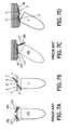
- the tilting axis 17 of each cutting unit 3 is located close to the other cutting units 3, which provides more adaptability to variations in angulation of the housing 1 relative to the skin surface 20 as is best seen in Figs. 7A to 7D .
- Figs. 7A and 7B the filled-in representation and the non filled-in representations of the cutting units 3, 103 show the cutting units 3, 103 tilted into different orientations.
- the cutting units 103 are each tiltable about an axis 117 that extends centrally relative to the shaving surface (see Figs. 7A and 7C ). More specifically, in such shaving apparatuses, the tilting axis 117 intersects a centre line of the shaving surface perpendicular to the shaving surface.
- Fig. 7C which illustrates the situation when holding a shaving apparatus according to the prior art at an angle relative to a skin surface 20 to be shaved
- one of the cutting units 103 is capable of accommodating to the angle between the housing 101 and the skin surface 20 to be shaved, whereas the other one of the cutting units 103 is not in contact with the skin.
- each cutting unit 3, or at least its suspension member is tiltable about a tilting axis 17 closer to a side of that cutting unit 3 facing the other cutting unit or units 3 than to an opposite side of the respective cutting unit 3.
- the external cutter may be arranged to be tiltable in any direction relative to the holder suspension, so that the shaving surface a further adaptability to the shape of the facial area to be shaved is obtained.
- the tiltability of the suspension members 6 about tilting axes 17 located closely together furthermore allows the portions of the shaving surface 7 that are at the outside of the arrangement of cutting units 3 to tilt over a large range of travel with a relatively simple construction, in particular if the suspension members 6 are supported by a holder 2 in the form of a centrally located post (see Figs. 3 and 5 ).
- This provides an improved adaptability to variations in curvature of the skin surface 20 to be shaved while maintaining an effective support of the skin by the skin support rim 13 that is part of the tiltable suspension member 6. Accordingly, variations in the contact pressure between, on the one hand, the portions of the shaving surfaces 7 of the cutting units 3 that are remote from each other and, on the other hand, the skin surface 20 are further reduced
- the suspension members 6 are pivotable independently from each other. As is best illustrated by Figs. 3 , 7B and 7D , this is advantageous for obtaining conformability to variations in angulation between the shaving apparatus and the skin surface 20 as well as to differences in the curvature of the skin surface 20 to be shaved.
- the pivoting axes 17 are located at identical distances from a centre line 24 at identical distance from centres of the cutting surfaces 7 of the cutting units 3.
- a uniformly shaped overall shaving surface is defined by the shaving surfaces 7 when the cutting units 3 are in the rest position shown in Figs. 1 and 3 .
Landscapes
- Life Sciences & Earth Sciences (AREA)
- Forests & Forestry (AREA)
- Engineering & Computer Science (AREA)
- Mechanical Engineering (AREA)
- Dry Shavers And Clippers (AREA)
Claims (14)
- Rasierapparat mit einem Gehäuse (1), welches mit einem Halter (2) versehen ist, an dem mindestens zwei Schneideinheiten (3) angebracht sind, die jeweils ein Außenmesser (4) mit einer äußeren Rasieroberfläche (7) zum Kontaktieren der Haut, welches durch Haareintrittsöffnungen (8) unterbrochen ist, ein Innenmesser (5), welches zur Bewegung entlang der Haareintrittsöffnungen (8) antreibbar ist, um durch die Haareintrittsöffnungen (8) ragende Haare abzuschneiden, sowie ein Aufhängeelement (6), mittels welchem das Außenmesser (4) relativ zu dem Halter (2) aufgehängt ist, aufweisen, wobei das Aufhängeelement (6) jeder Schneideinheit (3) relativ zu dem Halter (2) um eine Schwenkachse (17) individuell schwenkbar ist, dadurch gekennzeichnet, dass die Schwenkachse (17) jedes Aufhängeelements (6) näher an einem ersten Randteil (18) der Rasieroberfläche (7) der zugeordneten Schneideinheit (3) als an einem zweiten Randteil (19) der Rasieroberfläche (7) der zugeordneten Schneideinheit (3) gegenüber dem ersten Randteil (18) der Rasieroberfläche (7) positioniert ist.
- Rasierapparat nach Anspruch 1, wobei das Aufhängeelement (6) federbelastet ist, um das Aufhängeelement (6) in eine Ruheposition vorzuspannen, und gegen eine, das Aufhängeelement (6) in die Ruheposition vorspannende Kraft von der Ruheposition zu dem Gehäuse (1) hin in eine geneigte Position schwenkbar ist.
- Rasierapparat nach Anspruch 1 oder 2, wobei die Aufhängeelemente (6) unabhängig voneinander schwenkbar sind.
- Rasierapparat nach einem der vorangegangenen Ansprüche, wobei sich die Rasieroberfläche (7) des Außenmessers (4) über mindestens zwei verschiedene Rasierzonen (21-23) erstreckt, wobei eine erste Zone (21) der Rasierzonen näher an der Schwenkachse (17) als einer zweiten (23) der Rasierzonen positioniert ist, wobei die erste (21) der Rasierzonen zum Rasieren so eingerichtet ist, dass sich die Haut bei einem vorgegebenen Kontaktdruck weniger nah an dem Innenmesser (5) als in der zweiten (23) der Rasierzonen wölben kann.
- Rasierapparat nach Anspruch 4, wobei das Außenmesser (4) in der ersten Zone (21) dicker als in der zweiten Zone (22, 23) ist.
- Rasierapparat nach Anspruch 4 oder 5, welcher weiterhin einen Hautstützrand (13) umfasst, der ein freies Ende aufweist und sich dicht entlang eines Randes des Außenmessers (4) erstreckt, und wobei der Hautstützrand (13) weiter hervorragt und/oder in lateraler Richtung entlang des ersten Teils (21) der Rasieroberfläche (7) näher an dem Außenmesser (4) als entlang des zweiten Teils (23) der Rasieroberfläche (7) positioniert ist.
- Rasierapparat nach einem der vorangegangenen Ansprüche, wobei eine Rotation des Innenmessers (5) um eine Achse quer zu der Rasieroberfläche (7) relativ zu dem Außenmesser (4) antreibbar ist, und wobei die Schwenkachse (17) nah in Angrenzung an eine Außengrenze positioniert ist, welche eine perforierte Rasierfläche der Rasieroberfläche (7), in welcher die Öffnungen (8) vorgesehen sind, begrenzt.
- Rasierapparat nach Anspruch 7, wobei das Innenmesser (5) eine Schneidkante bzw. Schneidkanten (9) aufweist, welche entlang einer sich über eine Innenoberfläche des Außenmessers (4) erstreckende Kreisbahn bewegbar sind, und wobei ein Vorsprung der Schwenkachse (17) in einer Richtung senkrecht zu der Rasieroberfläche (7), an der Rasieroberfläche (7), eine Tangente zu der Kreisbahn bildet.
- Rasierapparat nach einem der vorangegangenen Ansprüche, wobei mindestens zwei Schneideinheiten (3) an dem Halter (2) angebracht sind, und wobei bei jedem Außenmesser (4) der erste Randteil (18) der Rasieroberfläche (7) näher an dem anderen Außenmesser (4) oder zumindest einem der anderen Außenmesser als der zweite Randteil (19) der Rasieroberfläche (7) ist.
- Rasierapparat nach Anspruch 9, wobei eine Abdeckung (37) zwischen den Schneideinheiten (3) eine Stützfläche bildet, um die Haut während des Rasierens zu kontaktieren, wobei sich die Stützfläche ausschließlich zwischen mindestens zwei der Schneideinheiten (3) erstreckt.
- Rasierapparat nach Anspruch 10, wobei die Abdeckung (37) einstellbar ist, um die Position einer Ebene einzustellen, entlang welcher sich die Stützfläche relativ zu der Position von mindestens einer Ebene erstreckt, entlang der sich die Rasieroberflächen (7) erstrecken.
- Rasierapparat nach einem der Ansprüche 9-11, wobei die Aufhängung federbelastet ist, um die Außenmesser (4) in Ruhepositionen vorzuspannen, in denen die Rasieroberflächen (7) in gegenseitig konvergierenden Richtungen gegenüberliegen, wobei die Rasieroberflächen (7) zumindest zu einer Konfiguration, in welcher sich die Rasieroberflächen (7) der Außenmesser in einer gegenseitig mehr parallelen Ausrichtung befinden, schwenkbar sind.
- Rasierapparat nach einem der Ansprüche 9-12, wobei die Schwenkachsen (17) in identischen Abständen von einer Mittellinie in identischem Abstand von Mittelpunkten der Schneidoberflächen (7) der Schneideinheiten (3) positioniert sind.
- Rasierapparat nach einem der vorangegangenen Ansprüche, wobei die Schwenkachse (17) tangential zu einem Messerzahnrad (11) ist, welches zur Rotation in einer Ebene parallel zu der Rasieroberfläche und zu einem in das Messerzahnrad (11) greifenden Antriebszahnrad (12) an dem Aufhängeelement (6) drehbar angebracht ist, um das Messerzahnrad (11) anzutreiben, und sich durch einen Bereich erstreckt, in welchem Zähne des Antriebszahnrads (12) in Zähne des Messerzahnrads (11) greifen.
Priority Applications (1)
| Application Number | Priority Date | Filing Date | Title |
|---|---|---|---|
| EP05825908A EP1833645B1 (de) | 2004-12-22 | 2005-12-19 | Rasierapparat |
Applications Claiming Priority (3)
| Application Number | Priority Date | Filing Date | Title |
|---|---|---|---|
| EP04106856 | 2004-12-22 | ||
| EP05825908A EP1833645B1 (de) | 2004-12-22 | 2005-12-19 | Rasierapparat |
| PCT/IB2005/054296 WO2006067721A1 (en) | 2004-12-22 | 2005-12-19 | Shaving apparatus |
Publications (2)
| Publication Number | Publication Date |
|---|---|
| EP1833645A1 EP1833645A1 (de) | 2007-09-19 |
| EP1833645B1 true EP1833645B1 (de) | 2009-05-06 |
Family
ID=36218615
Family Applications (1)
| Application Number | Title | Priority Date | Filing Date |
|---|---|---|---|
| EP05825908A Expired - Lifetime EP1833645B1 (de) | 2004-12-22 | 2005-12-19 | Rasierapparat |
Country Status (7)
| Country | Link |
|---|---|
| US (3) | US7930828B2 (de) |
| EP (1) | EP1833645B1 (de) |
| JP (1) | JP5021491B2 (de) |
| CN (1) | CN100575009C (de) |
| AT (1) | ATE430646T1 (de) |
| DE (1) | DE602005014387D1 (de) |
| WO (1) | WO2006067721A1 (de) |
Families Citing this family (39)
| Publication number | Priority date | Publication date | Assignee | Title |
|---|---|---|---|---|
| JP5021490B2 (ja) * | 2004-12-22 | 2012-09-05 | コーニンクレッカ フィリップス エレクトロニクス エヌ ヴィ | シェービングヘッドのための改良された駆動及び支持構造を備える回転シェーバー |
| WO2008010139A1 (en) * | 2006-07-14 | 2008-01-24 | Koninklijke Philips Electronics N.V. | Shaver having a space for collecting cut-off hairs |
| USRE48352E1 (en) * | 2006-11-20 | 2020-12-15 | Koninklijke Philips N.V. | Rotary shaver with improved support structure for shaving heads |
| US8455648B2 (en) * | 2008-04-24 | 2013-06-04 | Abbott Gmbh & Co. Kg | 1-(7-(hexahydropyrrolo [3,4-c] pyrrol-2 (1H)-yl) quinolin-4-yl) -3- (pyrazin-2-yl) urea derivatives and related compounds as glycogen synthase kinase 3 (GSK-3) |
| JP5339338B2 (ja) * | 2008-06-27 | 2013-11-13 | 株式会社泉精器製作所 | 回転式電気かみそり |
| JP5207457B2 (ja) * | 2008-06-27 | 2013-06-12 | 株式会社泉精器製作所 | 回転式電気かみそり |
| CN101683739B (zh) * | 2008-09-23 | 2011-05-18 | 叶常明 | 分离式电动剃须器的刀头结构 |
| US9009978B2 (en) | 2009-01-09 | 2015-04-21 | Koninklijke Philips N.V. | Shaver having spaces for collecting cut-off hairs |
| US9216513B2 (en) * | 2009-03-09 | 2015-12-22 | Koninklijke Philips N.V. | Shaving device with improved contour following |
| US9027251B2 (en) | 2009-04-29 | 2015-05-12 | Spectrum Brands, Inc. | Rotary electric shaver |
| US20100313426A1 (en) * | 2009-06-12 | 2010-12-16 | Terence Gordon Royle | Safety razor with pivot and rotation |
| US8474144B2 (en) * | 2009-08-12 | 2013-07-02 | The Gillette Company | Safety razor with rotational movement and locking button |
| US8745883B2 (en) | 2010-09-29 | 2014-06-10 | The Gillette Company | Razor handle with a rotatable portion |
| US8745882B2 (en) | 2010-09-29 | 2014-06-10 | The Gillette Company | Flexible and separable portion of a razor handle |
| EP2508309B1 (de) | 2011-04-05 | 2016-08-03 | The Gillette Company | Rasierergriff mit drehbarem Abschnitt |
| DE112012004401B4 (de) * | 2011-10-18 | 2015-11-12 | Shanghai Povos Electric Works Co. Ltd. | Drehender elektrischer Scherkopf |
| US8938885B2 (en) | 2012-05-01 | 2015-01-27 | The Gillette Company | Razor handle with a rotatable portion |
| CN104159713B (zh) * | 2012-08-03 | 2016-01-20 | 皇家飞利浦有限公司 | 具有锁定保持件的旋转剃须头 |
| US9174349B2 (en) | 2013-01-11 | 2015-11-03 | Spectrum Brands, Inc. | Rotary electric shaver |
| BR112015021949A2 (pt) | 2013-03-11 | 2017-07-18 | Koninklijke Philips Nv | dispositivo para cortar pelos |
| EP2964429B1 (de) * | 2013-05-16 | 2016-08-24 | Koninklijke Philips N.V. | Rasierkopf mit schwenkbarer rasiereinheit |
| EP2888086B1 (de) * | 2013-11-05 | 2016-03-16 | Koninklijke Philips N.V. | Körperpflegevorrichtung |
| US10335776B2 (en) * | 2013-12-16 | 2019-07-02 | Basf Corporation | Manganese-containing diesel oxidation catalyst |
| CN103934839B (zh) * | 2014-04-23 | 2017-03-01 | 李永友 | 头部变动角度互成夹角的电动剃须刀 |
| RU2655873C2 (ru) * | 2014-05-07 | 2018-05-29 | Конинклейке Филипс Н.В. | Улучшенное устройство для бритья |
| CA160094S (en) * | 2014-07-22 | 2015-07-16 | Philips Electronics Ltd | Comb for body groomer |
| USD765982S1 (en) * | 2015-01-28 | 2016-09-13 | Thomas Nichols | Handheld motorized facial brush having three floating heads |
| EP3573797B1 (de) * | 2017-01-27 | 2020-07-15 | Koninklijke Philips N.V. | Rasiereinheit mit schneideinheiten mit einem spülungsloch zur reinigung einer haarsammelkammer |
| US11186000B2 (en) * | 2017-01-27 | 2021-11-30 | Koninklijke Philips N.V. | Shaving unit and shaving apparatus with supporting structure for external cutting member |
| JP7197487B2 (ja) | 2017-01-27 | 2022-12-27 | コーニンクレッカ フィリップス エヌ ヴェ | 開放空間内に延在する駆動スピンドルを備えるシェービングユニット |
| WO2018138094A1 (en) | 2017-01-27 | 2018-08-02 | Koninklijke Philips N.V. | Shaving unit having cutting units with primary pivot axes |
| CN106671146B (zh) * | 2017-02-14 | 2018-08-17 | 广东罗曼智能科技股份有限公司 | 一种可拆卸浮动式剃须刀 |
| US10972672B2 (en) | 2017-06-05 | 2021-04-06 | Samsung Electronics Co., Ltd. | Device having cameras with different focal lengths and a method of implementing cameras with different focal lengths |
| US11565434B2 (en) * | 2017-11-21 | 2023-01-31 | Koninklijke Philips N.V. | Shaving unit having a retaining structure |
| CN109877884B (zh) * | 2019-01-30 | 2024-05-07 | 浙江超人科技股份有限公司 | 一种剃毛装置的剃刀头 |
| US20210069920A1 (en) * | 2019-09-05 | 2021-03-11 | Skull Shaver, Llc | Pivoting rotary 4 blade razor head |
| EP3825078A1 (de) * | 2019-11-19 | 2021-05-26 | Koninklijke Philips N.V. | Rasiereinheit und elektrischer rasierer mit der rasiereinheit |
| EP3842194A1 (de) * | 2019-12-24 | 2021-06-30 | Koninklijke Philips N.V. | Rasierapparat mit haarschneideeinheiten mit ersten und zweiten schwenkachsen |
| USD965892S1 (en) * | 2020-05-20 | 2022-10-04 | Koninklijke Philips N.V. | Head for shaver |
Family Cites Families (22)
| Publication number | Priority date | Publication date | Assignee | Title |
|---|---|---|---|---|
| BE459748A (de) * | 1941-05-06 | |||
| US2839225A (en) * | 1956-06-18 | 1958-06-17 | Dev Res Inc | Dispenser valve providing controlled flow and quick gassing |
| JPS4945907Y1 (de) * | 1970-12-04 | 1974-12-16 | ||
| US3858316A (en) * | 1971-09-25 | 1975-01-07 | Eduard Willem Tietjens | Shaving head having separately sprung blades |
| US4077120A (en) * | 1972-07-14 | 1978-03-07 | Bissell, Inc. | Dry shaver with floating peripherally supported shear plate |
| NL7304527A (de) * | 1973-03-31 | 1974-10-02 | ||
| NL7704475A (nl) * | 1977-04-25 | 1978-10-27 | Philips Nv | Scheerapparaat. |
| NL8402778A (nl) | 1984-09-12 | 1986-04-01 | Philips Nv | Scheerapparaat. |
| DE3843936C1 (de) | 1988-12-24 | 1990-05-31 | Braun Ag, 6000 Frankfurt, De | |
| DE9014307U1 (de) | 1990-10-15 | 1991-02-21 | Schultz, Horst, Dipl.-Ing., 6203 Hochheim | Haarentfernungsapparat |
| GB2266070A (en) * | 1992-04-10 | 1993-10-20 | Gillette Co | Dry shaver |
| JPH06171088A (ja) | 1992-12-08 | 1994-06-21 | Fuji Xerox Co Ltd | インクジェット記録ヘッド |
| US5625950A (en) * | 1994-07-19 | 1997-05-06 | U.S. Philips Corporation | Shaving apparatus |
| CN1096922C (zh) * | 1996-05-31 | 2002-12-25 | 皇家菲利浦电子有限公司 | 剃须装置 |
| KR100195137B1 (ko) | 1996-10-24 | 1999-06-15 | 윤종용 | 호환형 광픽업장치 |
| WO1998035794A1 (en) | 1997-02-17 | 1998-08-20 | Koninklijke Philips Electronics N.V. | Shaving apparatus |
| JP4635166B2 (ja) * | 2000-11-28 | 2011-02-16 | 株式会社泉精器製作所 | 回転式電気かみそり |
| JP2002346250A (ja) * | 2001-05-22 | 2002-12-03 | Izumi Products Co | 回転式電気かみそり |
| JP2005500145A (ja) * | 2001-08-23 | 2005-01-06 | コーニンクレッカ フィリップス エレクトロニクス エヌ ヴィ | ひげ剃り器の2つのタイプのシステム |
| JP4076455B2 (ja) * | 2003-02-25 | 2008-04-16 | 株式会社泉精器製作所 | 電気かみそり |
| DE20304170U1 (de) | 2003-03-15 | 2004-07-29 | Neoperl Gmbh | Einbauteil zum Einsetzen in eine Gas- oder Flüssigkeitsleitung |
| JP2007130166A (ja) * | 2005-11-09 | 2007-05-31 | Izumi Products Co | ロータリー式電気かみそり |
-
2005
- 2005-12-19 DE DE602005014387T patent/DE602005014387D1/de not_active Expired - Lifetime
- 2005-12-19 AT AT05825908T patent/ATE430646T1/de not_active IP Right Cessation
- 2005-12-19 WO PCT/IB2005/054296 patent/WO2006067721A1/en not_active Ceased
- 2005-12-19 EP EP05825908A patent/EP1833645B1/de not_active Expired - Lifetime
- 2005-12-19 US US11/722,462 patent/US7930828B2/en not_active Expired - Fee Related
- 2005-12-19 JP JP2007547748A patent/JP5021491B2/ja not_active Expired - Lifetime
- 2005-12-19 CN CN200580044013A patent/CN100575009C/zh not_active Expired - Lifetime
-
2011
- 2011-03-25 US US13/071,605 patent/US8595939B2/en not_active Expired - Lifetime
-
2013
- 2013-10-24 US US14/061,813 patent/US9061428B2/en not_active Expired - Lifetime
Also Published As
| Publication number | Publication date |
|---|---|
| US20110167641A1 (en) | 2011-07-14 |
| WO2006067721A1 (en) | 2006-06-29 |
| US20100018058A1 (en) | 2010-01-28 |
| US7930828B2 (en) | 2011-04-26 |
| JP5021491B2 (ja) | 2012-09-05 |
| EP1833645A1 (de) | 2007-09-19 |
| CN101084091A (zh) | 2007-12-05 |
| DE602005014387D1 (de) | 2009-06-18 |
| JP2008525085A (ja) | 2008-07-17 |
| US8595939B2 (en) | 2013-12-03 |
| US9061428B2 (en) | 2015-06-23 |
| ATE430646T1 (de) | 2009-05-15 |
| US20140047717A1 (en) | 2014-02-20 |
| CN100575009C (zh) | 2009-12-30 |
Similar Documents
| Publication | Publication Date | Title |
|---|---|---|
| EP1833645B1 (de) | Rasierapparat | |
| EP0719203B1 (de) | Rasierapparat | |
| US8061040B2 (en) | Cutter blade assembly and dry shaver for variable height of cut | |
| JP2023524795A (ja) | 電気髭トリマー | |
| US20040055156A1 (en) | Safety razor | |
| EP3907048B1 (de) | Elektrischer bartschneider | |
| US20080295340A1 (en) | Free pivoting cutting head and blade assembly for hair cutter | |
| RU2610982C2 (ru) | Усовершенствованная бреющая головка с возможностью регулирования куполообразной формы | |
| US20210229301A1 (en) | Electric beard trimmer | |
| JP2019171034A (ja) | 体毛除去装置 | |
| US20050223560A1 (en) | Dry shaver for variable heights of cut | |
| US4590674A (en) | Shaving implement having adjustable annular blades | |
| RU2101166C1 (ru) | Режущая головка электробритвы | |
| JP4034665B2 (ja) | 回転式電気かみそり | |
| US20240375303A1 (en) | Razor | |
| JP3928115B2 (ja) | ローラを備えた剃刀 | |
| JPH0436793Y2 (de) | ||
| JPS6029980Y2 (ja) | 電気カミソリ | |
| JPS5835188Y2 (ja) | 安全かみそり | |
| WO2007060646A1 (en) | Cutter blade assembly and dry shaver for variable height of cut | |
| HK1050505A (en) | Dry shaver for variable height of cut | |
| JPS6230788B2 (de) |
Legal Events
| Date | Code | Title | Description |
|---|---|---|---|
| PUAI | Public reference made under article 153(3) epc to a published international application that has entered the european phase |
Free format text: ORIGINAL CODE: 0009012 |
|
| 17P | Request for examination filed |
Effective date: 20070723 |
|
| AK | Designated contracting states |
Kind code of ref document: A1 Designated state(s): AT BE BG CH CY CZ DE DK EE ES FI FR GB GR HU IE IS IT LI LT LU LV MC NL PL PT RO SE SI SK TR |
|
| DAX | Request for extension of the european patent (deleted) | ||
| 17Q | First examination report despatched |
Effective date: 20080422 |
|
| GRAP | Despatch of communication of intention to grant a patent |
Free format text: ORIGINAL CODE: EPIDOSNIGR1 |
|
| GRAS | Grant fee paid |
Free format text: ORIGINAL CODE: EPIDOSNIGR3 |
|
| GRAA | (expected) grant |
Free format text: ORIGINAL CODE: 0009210 |
|
| AK | Designated contracting states |
Kind code of ref document: B1 Designated state(s): AT BE BG CH CY CZ DE DK EE ES FI FR GB GR HU IE IS IT LI LT LU LV MC NL PL PT RO SE SI SK TR |
|
| REG | Reference to a national code |
Ref country code: GB Ref legal event code: FG4D |
|
| REG | Reference to a national code |
Ref country code: CH Ref legal event code: EP |
|
| REG | Reference to a national code |
Ref country code: IE Ref legal event code: FG4D |
|
| REF | Corresponds to: |
Ref document number: 602005014387 Country of ref document: DE Date of ref document: 20090618 Kind code of ref document: P |
|
| PG25 | Lapsed in a contracting state [announced via postgrant information from national office to epo] |
Ref country code: AT Free format text: LAPSE BECAUSE OF FAILURE TO SUBMIT A TRANSLATION OF THE DESCRIPTION OR TO PAY THE FEE WITHIN THE PRESCRIBED TIME-LIMIT Effective date: 20090506 Ref country code: FI Free format text: LAPSE BECAUSE OF FAILURE TO SUBMIT A TRANSLATION OF THE DESCRIPTION OR TO PAY THE FEE WITHIN THE PRESCRIBED TIME-LIMIT Effective date: 20090506 Ref country code: ES Free format text: LAPSE BECAUSE OF FAILURE TO SUBMIT A TRANSLATION OF THE DESCRIPTION OR TO PAY THE FEE WITHIN THE PRESCRIBED TIME-LIMIT Effective date: 20090817 Ref country code: PT Free format text: LAPSE BECAUSE OF FAILURE TO SUBMIT A TRANSLATION OF THE DESCRIPTION OR TO PAY THE FEE WITHIN THE PRESCRIBED TIME-LIMIT Effective date: 20090906 Ref country code: LT Free format text: LAPSE BECAUSE OF FAILURE TO SUBMIT A TRANSLATION OF THE DESCRIPTION OR TO PAY THE FEE WITHIN THE PRESCRIBED TIME-LIMIT Effective date: 20090506 |
|
| NLV1 | Nl: lapsed or annulled due to failure to fulfill the requirements of art. 29p and 29m of the patents act | ||
| PG25 | Lapsed in a contracting state [announced via postgrant information from national office to epo] |
Ref country code: PL Free format text: LAPSE BECAUSE OF FAILURE TO SUBMIT A TRANSLATION OF THE DESCRIPTION OR TO PAY THE FEE WITHIN THE PRESCRIBED TIME-LIMIT Effective date: 20090506 Ref country code: LV Free format text: LAPSE BECAUSE OF FAILURE TO SUBMIT A TRANSLATION OF THE DESCRIPTION OR TO PAY THE FEE WITHIN THE PRESCRIBED TIME-LIMIT Effective date: 20090506 Ref country code: IS Free format text: LAPSE BECAUSE OF FAILURE TO SUBMIT A TRANSLATION OF THE DESCRIPTION OR TO PAY THE FEE WITHIN THE PRESCRIBED TIME-LIMIT Effective date: 20090906 Ref country code: SI Free format text: LAPSE BECAUSE OF FAILURE TO SUBMIT A TRANSLATION OF THE DESCRIPTION OR TO PAY THE FEE WITHIN THE PRESCRIBED TIME-LIMIT Effective date: 20090506 Ref country code: SE Free format text: LAPSE BECAUSE OF FAILURE TO SUBMIT A TRANSLATION OF THE DESCRIPTION OR TO PAY THE FEE WITHIN THE PRESCRIBED TIME-LIMIT Effective date: 20090806 Ref country code: NL Free format text: LAPSE BECAUSE OF FAILURE TO SUBMIT A TRANSLATION OF THE DESCRIPTION OR TO PAY THE FEE WITHIN THE PRESCRIBED TIME-LIMIT Effective date: 20090506 |
|
| PG25 | Lapsed in a contracting state [announced via postgrant information from national office to epo] |
Ref country code: CZ Free format text: LAPSE BECAUSE OF FAILURE TO SUBMIT A TRANSLATION OF THE DESCRIPTION OR TO PAY THE FEE WITHIN THE PRESCRIBED TIME-LIMIT Effective date: 20090506 Ref country code: DK Free format text: LAPSE BECAUSE OF FAILURE TO SUBMIT A TRANSLATION OF THE DESCRIPTION OR TO PAY THE FEE WITHIN THE PRESCRIBED TIME-LIMIT Effective date: 20090506 Ref country code: EE Free format text: LAPSE BECAUSE OF FAILURE TO SUBMIT A TRANSLATION OF THE DESCRIPTION OR TO PAY THE FEE WITHIN THE PRESCRIBED TIME-LIMIT Effective date: 20090506 Ref country code: RO Free format text: LAPSE BECAUSE OF FAILURE TO SUBMIT A TRANSLATION OF THE DESCRIPTION OR TO PAY THE FEE WITHIN THE PRESCRIBED TIME-LIMIT Effective date: 20090506 |
|
| PG25 | Lapsed in a contracting state [announced via postgrant information from national office to epo] |
Ref country code: BE Free format text: LAPSE BECAUSE OF FAILURE TO SUBMIT A TRANSLATION OF THE DESCRIPTION OR TO PAY THE FEE WITHIN THE PRESCRIBED TIME-LIMIT Effective date: 20090506 Ref country code: SK Free format text: LAPSE BECAUSE OF FAILURE TO SUBMIT A TRANSLATION OF THE DESCRIPTION OR TO PAY THE FEE WITHIN THE PRESCRIBED TIME-LIMIT Effective date: 20090506 |
|
| PLBE | No opposition filed within time limit |
Free format text: ORIGINAL CODE: 0009261 |
|
| STAA | Information on the status of an ep patent application or granted ep patent |
Free format text: STATUS: NO OPPOSITION FILED WITHIN TIME LIMIT |
|
| PG25 | Lapsed in a contracting state [announced via postgrant information from national office to epo] |
Ref country code: BG Free format text: LAPSE BECAUSE OF FAILURE TO SUBMIT A TRANSLATION OF THE DESCRIPTION OR TO PAY THE FEE WITHIN THE PRESCRIBED TIME-LIMIT Effective date: 20090806 |
|
| 26N | No opposition filed |
Effective date: 20100209 |
|
| PG25 | Lapsed in a contracting state [announced via postgrant information from national office to epo] |
Ref country code: MC Free format text: LAPSE BECAUSE OF NON-PAYMENT OF DUE FEES Effective date: 20100701 |
|
| REG | Reference to a national code |
Ref country code: CH Ref legal event code: PL |
|
| PG25 | Lapsed in a contracting state [announced via postgrant information from national office to epo] |
Ref country code: CH Free format text: LAPSE BECAUSE OF NON-PAYMENT OF DUE FEES Effective date: 20091231 Ref country code: LI Free format text: LAPSE BECAUSE OF NON-PAYMENT OF DUE FEES Effective date: 20091231 Ref country code: IE Free format text: LAPSE BECAUSE OF NON-PAYMENT OF DUE FEES Effective date: 20091219 Ref country code: GR Free format text: LAPSE BECAUSE OF FAILURE TO SUBMIT A TRANSLATION OF THE DESCRIPTION OR TO PAY THE FEE WITHIN THE PRESCRIBED TIME-LIMIT Effective date: 20090807 |
|
| PG25 | Lapsed in a contracting state [announced via postgrant information from national office to epo] |
Ref country code: IT Free format text: LAPSE BECAUSE OF FAILURE TO SUBMIT A TRANSLATION OF THE DESCRIPTION OR TO PAY THE FEE WITHIN THE PRESCRIBED TIME-LIMIT Effective date: 20090506 |
|
| PG25 | Lapsed in a contracting state [announced via postgrant information from national office to epo] |
Ref country code: LU Free format text: LAPSE BECAUSE OF NON-PAYMENT OF DUE FEES Effective date: 20091219 |
|
| PG25 | Lapsed in a contracting state [announced via postgrant information from national office to epo] |
Ref country code: HU Free format text: LAPSE BECAUSE OF FAILURE TO SUBMIT A TRANSLATION OF THE DESCRIPTION OR TO PAY THE FEE WITHIN THE PRESCRIBED TIME-LIMIT Effective date: 20091107 |
|
| PG25 | Lapsed in a contracting state [announced via postgrant information from national office to epo] |
Ref country code: TR Free format text: LAPSE BECAUSE OF FAILURE TO SUBMIT A TRANSLATION OF THE DESCRIPTION OR TO PAY THE FEE WITHIN THE PRESCRIBED TIME-LIMIT Effective date: 20090506 |
|
| PG25 | Lapsed in a contracting state [announced via postgrant information from national office to epo] |
Ref country code: CY Free format text: LAPSE BECAUSE OF FAILURE TO SUBMIT A TRANSLATION OF THE DESCRIPTION OR TO PAY THE FEE WITHIN THE PRESCRIBED TIME-LIMIT Effective date: 20090506 |
|
| REG | Reference to a national code |
Ref country code: DE Ref legal event code: R082 Ref document number: 602005014387 Country of ref document: DE Representative=s name: VOLMER, GEORG, DIPL.-ING., DE |
|
| REG | Reference to a national code |
Ref country code: DE Ref legal event code: R081 Ref document number: 602005014387 Country of ref document: DE Owner name: KONINKLIJKE PHILIPS N.V., NL Free format text: FORMER OWNER: KONINKLIJKE PHILIPS ELECTRONICS N.V., EINDHOVEN, NL Effective date: 20140331 Ref country code: DE Ref legal event code: R082 Ref document number: 602005014387 Country of ref document: DE Representative=s name: VOLMER, GEORG, DIPL.-ING., DE Effective date: 20140331 Ref country code: DE Ref legal event code: R082 Ref document number: 602005014387 Country of ref document: DE Representative=s name: MEISSNER BOLTE PATENTANWAELTE RECHTSANWAELTE P, DE Effective date: 20140331 |
|
| REG | Reference to a national code |
Ref country code: FR Ref legal event code: CA Effective date: 20141126 Ref country code: FR Ref legal event code: CD Owner name: KONINKLIJKE PHILIPS N.V., NL Effective date: 20141126 |
|
| REG | Reference to a national code |
Ref country code: FR Ref legal event code: PLFP Year of fee payment: 11 |
|
| REG | Reference to a national code |
Ref country code: FR Ref legal event code: PLFP Year of fee payment: 12 |
|
| REG | Reference to a national code |
Ref country code: DE Ref legal event code: R082 Ref document number: 602005014387 Country of ref document: DE Representative=s name: MEISSNER BOLTE PATENTANWAELTE RECHTSANWAELTE P, DE |
|
| REG | Reference to a national code |
Ref country code: FR Ref legal event code: PLFP Year of fee payment: 13 |
|
| PGFP | Annual fee paid to national office [announced via postgrant information from national office to epo] |
Ref country code: GB Payment date: 20241217 Year of fee payment: 20 |
|
| PGFP | Annual fee paid to national office [announced via postgrant information from national office to epo] |
Ref country code: FR Payment date: 20241227 Year of fee payment: 20 |
|
| PGFP | Annual fee paid to national office [announced via postgrant information from national office to epo] |
Ref country code: DE Payment date: 20241227 Year of fee payment: 20 |
|
| REG | Reference to a national code |
Ref country code: DE Ref legal event code: R071 Ref document number: 602005014387 Country of ref document: DE |
|
| REG | Reference to a national code |
Ref country code: GB Ref legal event code: PE20 Expiry date: 20251218 |