EP1834323B1 - Durchführen einer fehlerfreien zugriffsoperation auf einem mehrschichtigen datenträger - Google Patents
Durchführen einer fehlerfreien zugriffsoperation auf einem mehrschichtigen datenträger Download PDFInfo
- Publication number
- EP1834323B1 EP1834323B1 EP05795332.5A EP05795332A EP1834323B1 EP 1834323 B1 EP1834323 B1 EP 1834323B1 EP 05795332 A EP05795332 A EP 05795332A EP 1834323 B1 EP1834323 B1 EP 1834323B1
- Authority
- EP
- European Patent Office
- Prior art keywords
- recording layer
- address
- layer
- recording
- optical disc
- Prior art date
- Legal status (The legal status is an assumption and is not a legal conclusion. Google has not performed a legal analysis and makes no representation as to the accuracy of the status listed.)
- Expired - Lifetime
Links
Images






Classifications
-
- G—PHYSICS
- G11—INFORMATION STORAGE
- G11B—INFORMATION STORAGE BASED ON RELATIVE MOVEMENT BETWEEN RECORD CARRIER AND TRANSDUCER
- G11B7/00—Recording or reproducing by optical means, e.g. recording using a thermal beam of optical radiation by modifying optical properties or the physical structure, reproducing using an optical beam at lower power by sensing optical properties; Record carriers therefor
- G11B7/08—Disposition or mounting of heads or light sources relatively to record carriers
- G11B7/085—Disposition or mounting of heads or light sources relatively to record carriers with provision for moving the light beam into, or out of, its operative position or across tracks, otherwise than during the transducing operation, e.g. for adjustment or preliminary positioning or track change or selection
- G11B7/08505—Methods for track change, selection or preliminary positioning by moving the head
- G11B7/08511—Methods for track change, selection or preliminary positioning by moving the head with focus pull-in only
-
- G—PHYSICS
- G11—INFORMATION STORAGE
- G11B—INFORMATION STORAGE BASED ON RELATIVE MOVEMENT BETWEEN RECORD CARRIER AND TRANSDUCER
- G11B27/00—Editing; Indexing; Addressing; Timing or synchronising; Monitoring; Measuring tape travel
- G11B27/10—Indexing; Addressing; Timing or synchronising; Measuring tape travel
- G11B27/102—Programmed access in sequence to addressed parts of tracks of operating record carriers
- G11B27/105—Programmed access in sequence to addressed parts of tracks of operating record carriers of operating discs
-
- G—PHYSICS
- G11—INFORMATION STORAGE
- G11B—INFORMATION STORAGE BASED ON RELATIVE MOVEMENT BETWEEN RECORD CARRIER AND TRANSDUCER
- G11B7/00—Recording or reproducing by optical means, e.g. recording using a thermal beam of optical radiation by modifying optical properties or the physical structure, reproducing using an optical beam at lower power by sensing optical properties; Record carriers therefor
- G11B2007/0003—Recording, reproducing or erasing systems characterised by the structure or type of the carrier
- G11B2007/0009—Recording, reproducing or erasing systems characterised by the structure or type of the carrier for carriers having data stored in three dimensions, e.g. volume storage
- G11B2007/0013—Recording, reproducing or erasing systems characterised by the structure or type of the carrier for carriers having data stored in three dimensions, e.g. volume storage for carriers having multiple discrete layers
-
- G—PHYSICS
- G11—INFORMATION STORAGE
- G11B—INFORMATION STORAGE BASED ON RELATIVE MOVEMENT BETWEEN RECORD CARRIER AND TRANSDUCER
- G11B20/00—Signal processing not specific to the method of recording or reproducing; Circuits therefor
- G11B20/10—Digital recording or reproducing
- G11B2020/10916—Seeking data on the record carrier for preparing an access to a specific address
-
- G—PHYSICS
- G11—INFORMATION STORAGE
- G11B—INFORMATION STORAGE BASED ON RELATIVE MOVEMENT BETWEEN RECORD CARRIER AND TRANSDUCER
- G11B20/00—Signal processing not specific to the method of recording or reproducing; Circuits therefor
- G11B20/10—Digital recording or reproducing
- G11B20/12—Formatting, e.g. arrangement of data block or words on the record carriers
- G11B20/1217—Formatting, e.g. arrangement of data block or words on the record carriers on discs
- G11B2020/1218—Formatting, e.g. arrangement of data block or words on the record carriers on discs wherein the formatting concerns a specific area of the disc
- G11B2020/1235—Formatting, e.g. arrangement of data block or words on the record carriers on discs wherein the formatting concerns a specific area of the disc session, i.e. a contiguous area having its own lead-in area, program area and lead-out area
-
- G—PHYSICS
- G11—INFORMATION STORAGE
- G11B—INFORMATION STORAGE BASED ON RELATIVE MOVEMENT BETWEEN RECORD CARRIER AND TRANSDUCER
- G11B2220/00—Record carriers by type
- G11B2220/20—Disc-shaped record carriers
- G11B2220/23—Disc-shaped record carriers characterised in that the disc has a specific layer structure
- G11B2220/235—Multilayer discs, i.e. multiple recording layers accessed from the same side
- G11B2220/237—Multilayer discs, i.e. multiple recording layers accessed from the same side having exactly two recording layers
-
- G—PHYSICS
- G11—INFORMATION STORAGE
- G11B—INFORMATION STORAGE BASED ON RELATIVE MOVEMENT BETWEEN RECORD CARRIER AND TRANSDUCER
- G11B2220/00—Record carriers by type
- G11B2220/20—Disc-shaped record carriers
- G11B2220/25—Disc-shaped record carriers characterised in that the disc is based on a specific recording technology
- G11B2220/2537—Optical discs
Definitions
- the present invention generally related to reproduction methods, optical disc apparatuses, programs, and record media, and particularly relates to a method of reproducing information recorded on an optical disc having a plurality of recording layers, an optical disc apparatus operable to reproduce information recorded on an optical disc having a plurality of recording layers, a program for use in such an optical disc apparatus, and a recording medium having such a program recorded thereon.
- optical discs such as DVDs (digital versatile discs) have been attracting attention as information recording media for storing computer programs, music information, and video information (hereinafter also referred to as "contents").
- contents information recording media for storing computer programs, music information, and video information (hereinafter also referred to as "contents").
- optical disc apparatuses for reproducing information recorded on the optical discs are now becoming widely used.
- one of the two scan paths (scan path A and scan path B) is employed as a scan path when scanning an optical spot from an address (current address) on one recording layer (referred to as X) to an address (target address) on the other recording layer (referred to as Y).
- scan path A the focus is jumped from the recording layer X to the recording layer Y at the current address position, followed by performing a seek operation toward the target address on the recording layer Y.
- the scan path B an address on the recording layer X at the same position as the target address in terms of the disc radial direction is set as a tentative target address, and a seek operation is performed from the current address to the tentative target address, followed by jumping the focus at the tentative target address position from the recording layer X to the recording layer Y (see Patent Document 1, for example).
- the scan path A is easier than the scan path B in terms of achieving high-speed scan, and is thus employed in many information reproducing apparatuses adapted to the single-side two-layer disc. Further, there are apparatuses that perform focus jump and seek operation at the same time (see Patent Document 2, for example).
- a tentative target address a' is set, followed by performing a seek operation to the tentative target address a'on the layer LAYER-1 when the scan path B is employed.
- the tentative target address a' is situated in the unrecorded area. There may thus be a risk of suffering a seek error without being able to acquire address information contained in reproduced data.
- an information reproducing apparatus adapted to a single-side two-layer disc may fail to reproduce information recorded on a target address even though the target address is situated in the prerecorded area.
- US2004/076084A discloses a method of reproducing information recorded on an optical disc having a plurality of recording layers inclusive of a first recording layer and a second recording layer, comprising the steps of:
- the invention is the method, apparatus, program and medium of Claims 1, 8, 15 and 16.
- the present invention can provide a scheme for reproducing information from an optical disc that substantially obviates one or more problems caused by the limitations and disadvantages of the related art.
- the present invention can also provide a scheme for reproducing information from an optical disc that can properly reproduce information in a stable manner from an optical disc having a plurality of recording layers in which a prerecorded area and an unrecorded area are coexistent.
- the control unit can obtain proper address information necessary for the scan with sufficient accuracy along the way as the scan is performed. Consequently, the optical spot is accurately formed at the second address, so that the processing unit can reproduce information properly by use of the signal output from the optical pickup unit. That is, information is reproduced properly in a stable manner from an optical disc having a plurality of recording layers in which a prerecorded area and an unrecorded area are coexistent.
- FIG. 1 is a drawing showing a schematic configuration of an optical disc apparatus 20 according to the embodiment of the present invention.
- the optical disc apparatus 20 shown in Fig. 1 includes a spindle motor 22 for revolving an optical disc 15 having a plurality of recording layers on which a track or tracks are formed in a spiral form or concentric manner, an optical pickup apparatus 23, a seek motor 21, a laser control circuit 24, a drive control circuit 26, a reproduced signal processing circuit 28, a buffer RAM 34, a buffer manager 37, an interface 38, a flash memory 39, a CPU 40, and a RAM 41.
- the optical disc apparatus 20 serves as an information reproducing apparatus for reproducing information recorded on the optical disc 15. It should be noted that arrows illustrated in Fig. 1 demonstrate representative flows of signals and information, and are not intended to illustrate all the connections between the blocks.
- the optical disc apparatus 20 is adapted to the single-side two-layer DVD-ROM and the single-side two-layer DVD-R.
- the optical pickup apparatus 23 focuses laser light on a recording layer (hereinafter referred to as "target recording layer") selected from the plurality of recording layers of the optical disc 15, and receives reflected light from the target recording layer.
- the optical pickup apparatus 23 includes a semiconductor laser, an objective lens for condensing the light flux emitted from the semiconductor laser so as to form an optical spot on the target recording layer, a photo detector for detecting returning light reflected from the target recording layer, and a drive system (focusing actuator and tracking actuator) for driving the objective lens (not shown).
- the photo detector has a plurality of photo detector elements (or plurality of photo detecting areas), each of which generates a signal (photoelectric conversion signal) responsive to the amount of received light for provision to the reproduced signal processing circuit 28.
- the focusing actuator serves to drive the objective lens in the direction of the optical axis of the objective lens.
- the tracking actuator serves to drive the objective lens in a tracking direction, which is perpendicular to both the tangential direction of the track and the direction of the optical axis of the objective lens.
- the seek motor 21 is a motor that drives the optical pickup apparatus 23 in the sledge direction.
- the seek motor 21 drives the optical pickup apparatus 23 to position an optical spot near the target position, which is referred to as a coarse seek operation or simply as coarse seek.
- the drive control circuit 26 generates a tracking actuator drive signal based on the track error signal supplied from the reproduced signal processing circuit 28 in order to correct the positioning error of the objective lens in the tracking direction. Further, the drive control circuit 26 generates a focusing actuator drive signal based on the focus error signal in order to correct the focusing error of the objective lens. These drive signals are supplied to the optical pickup apparatus 23. With this provision, tracking control and focus control are performed.
- the operation that drives the tracking actuator to shift the objective lens to form an optical spot at the target position is referred to as a fine seek operation or simply as fine seek.
- the buffer RAM 34 temporarily stores the data (reproduced data) reproduced from the optical disc 15.
- the inputting/outputting of data into/from the buffer RAM 34 is managed by the buffer manager 37.
- the laser control circuit 24 controls the power of light emission of the semiconductor laser provided in the optical pickup apparatus 23. Specifically, the laser control circuit 24 generates a semiconductor laser drive signal for provision to the optical pickup apparatus 23.
- the interface 38 is a two-way communication interface to communicate with a higher-order apparatus 90 (e.g., personal computer), and complies with interface standards such as ATAPI (AT Attachment Packet Interface), SCSI (Small Computer System Interface), and USB (Universal Serial Bus).
- ATAPI AT Attachment Packet Interface
- SCSI Serial Computer System Interface
- USB Universal Serial Bus
- the flash memory 39 stores therein various programs and data indicative of the light emission characteristics of the semiconductor laser.
- the programs include a program of the present invention written in such codes as to be decodable by the CPU 40.
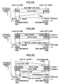
- Figs. 2A through 2C are illustrative drawings showing the layout of an information area of the DVD-ROM that is commercially available.
- the single-layer DVD-ROM has an Information Area that includes a Lead-in Zone, a Data Zone, and a Lead-out Zone arranged in the order named from the inner circumference to the outer circumference in the recording layer.
- Consecutive physical addresses (PBA) that increase from the Lead-in Zone to the Lead-out Zone, i.e., from the disc inner circumference to the outer circumference, are assigned.
- PBA physical addresses
- the track path extends from the Lead-in Zone to the Lead-out Zone.
- the physical addresses consecutively increase from the Intermediate Zone to the Lead-out Zone.
- the track path extends (is directed) from the Lead-in Zone to the Intermediate Zone in the layer LAYER-0, and extends (is directed) from the Intermediate Zone to the Lead-out Zone in the layer LAYER-1. Because of this, the layers LAYER-0 and LAYER-1 can be treated as a single continuous layer.
- the start position of the Lead-in Zone and the end position of the Lead-out Zone, the end position of the Data Zone of the layer LAYER-0 and the start position of the Data Zone of the layer LAYER-1, and the start and end positions of the Intermediate Zone of each recording layer are situated at the same radial position.
- the start position of the Data Zone of the layer LAYER-0 and the end position of the Data Zone of the layer LAYER-1 may differ.
- a Lead-out is recorded in the differential portion as in the case of the single-side two-layer DVD-ROM according to the PTP method.
- the optical disc 15 is a two-layer disc complying with the standard of the single-side two-layer DVD+R.
- the single-side two-layer DVD+R is compatible with the single-side two-layer DVD+ROM according to the OTP method.
- a DVD+R having a single recording layer may be referred to as a "single-layer DVD+R".
- the physical addresses consecutively increase from the Intermediate Zone to the Lead-out Zone, i.e., from the disc outer circumference to the inner circumference.
- the optical disc 15 is mounted in the optical disc apparatus 20 such that the layer LAYER-0 is the recording layer that is situated closer to the optical pickup apparatus 23.
- the track path extends (is directed) from the Lead-in Zone to the Intermediate Zone in the layer LAYER-0, and extends (is directed) from the Intermediate Zone to the Lead-out Zone in the layer LAYER-1, as in the single-side two-layer DVD+ROM according to the OTP method described above.
- two scan paths are given as a choice of a scan path for scanning an optical spot from the current address (first address) in one recording layer (first recording layer) of the layers LAYER-0 and LAYER-1 to a target address (second address) in the other recording layer (second recording layer).
- first scan path and second scan path are given as a choice of a scan path for scanning an optical spot from the current address (first address) in one recording layer (first recording layer) of the layers LAYER-0 and LAYER-1 to a target address (second address) in the other recording layer (second recording layer).
- a description will be given of a specific example of each scan path with respect to Fig. 4A and Fig. 4B.
- Figs. 4A and 4B are illustrative drawings showing examples in which an optical spot is scanned from a current address in the layer LAYER-0 to a target address in the layer LAYER-1.
- a multi-track and multi-session recording method is adopted as in the case of the single-layer DVD-R (see ECMA-349, for example).
- a brief description will be given of a multi-session recording method with respect to the optical disc 15. It is assumed that the recording of user data is performed with respect to the layer LAYER-0 ahead of the layer LAYER-1. Namely, according to the order of recording, the layer LAYER-0 is the first to be recorded, and the layer LAYER-1 is the second to be recorded.
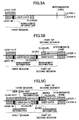
- Fig. 5A is an illustrative drawing showing an example of a situation in which user data is recorded in a first session, followed by the closure of the session.
- the first session includes a Lead-in, user data, and a closure.
- Management information inclusive of information on the recording position (i.e., the start address and end address) of a fragment that exists in the first session is recorded in the management information area provided in the Lead-in Zone.
- the Lead-out Zone of the layer LAYER-1 also stores predetermined information.
- Fig. 5B is an illustrative drawing showing an example of a situation in which a next session (second session) is additionally recorded, crossing the boundary between the two recording layers LAYER-0 and LAYER-1, followed by the closure of the session.
- the second session is recorded in an area immediately following the first session, and includes an Intro, user data, and a closure.
- the user data is recorded, crossing the boundary between the two recording layers.
- the Intermediate Zone of each recording layer has data stored therein indicating that the zone is an intermediate zone.
- Management information inclusive of information on the recording position (i.e., the start address and end address) of a fragment situated in the second session and information on the recording position (i.e., the start address and end address) of the first session is recorded in the management information area provided in the Intro of the second session.
- Fig. 5C is an illustrative drawing showing an example of a situation in which a next session (third session) is additionally recorded, followed by a finalizing process.
- the third session is recorded in an area immediately following the second session (i.e., an area closer to the inner circumference side), and includes an Intro, user data, and a Lead-out.
- Management information inclusive of information on the recording position (i.e., the start address and end address) of a fragment situated in the third session, information on the recording position (i.e., the start address and end address) of the second session, and information on the recording position (i.e., the start address and end address) of the first session is recorded in the management information area provided in the Intro of the third session.
- a new Lead-out In an unrecorded area following the third session is recorded a new Lead-out, thereby turning all the Information Area into a prerecorded area.
- the optical disc 15 having a state as shown in Fig. 5B in which the second session is closed after being recorded following the first session is mounted in the optical disc apparatus 20 having the configuration as previously described, and the upper-order apparatus 90 issues a command requesting reproduction.
- all the Data Zone of the layer LAYER-0 is a prerecorded area
- the Data Zone of the layer Layer-1 includes an unrecorded area therein on the inner circumference side.
- Fig. 6 is a flowchart showing an algorithm defining a series of processes performed by the CPU 40.
- the start address of a program corresponding to the flowchart of Fig. 6 stored in the flash memory 39 is set in the program counter of the CPU 40. With this, the process (reproduction process) responding to the reproduction requesting command commences.
- target address attached to the reproduction requesting command is extracted from the reproduction requesting command.
- the recording layer to which this target address belongs (hereinafter referred to as a "target recording layer Lt") is then identified.
- the address (current address) of the area in which the optical spot is currently positioned is identified based on the address information supplied from the reproduced signal processing circuit 28.
- the recording layer to which the current address belongs (hereinafter referred to as a "current recording layer Ln") is identified.
- step 409 a check is made as to whether the target recording layer Lt differs from the current recording layer Ln. If the target recording layer Lt differs from the current recording layer Ln, the check result is affirmative, so that the procedure moves to step 411.
- the second scan path is selected among the first scan path and the second scan path.
- an address in a vicinity of the same radial direction as the target address in the current recording layer Ln is set as a tentative target address.
- the direction extending from the tentative target address to the target address along the radial direction of the optical disc is the same as the direction in which the address increases in the layer LAYER-1.
- the address of the position in the layer LAYER-0 that is located 0.1 mm off to the outer circumference side from the radial position of the target address is set as the tentative target address.
- optical discs having a plurality of recording layers are manufactured by gluing the individual recording layers together after they are separately produced.
- the relative positions of the individual recording layers may deviate from the designed positions. Even if such deviation is within a tolerable range, there may be a recording layer in which the actual radial position on the optical disc may not match the radial position obtained of the address due to the deviation.
- the tentative target address is set to the same radial position as the target address, thus, the address after a focus jump may end up being different from the target address.
- the target address is close to an unrecorded area, there is a risk of accessing the unrecorded area upon the focus jump.
- the direction extending from the tentative target address to the target address along the radial direction of the optical disc is set in the same direction as the direction in which the address increases in the target recording layer.
- the tentative target address is positioned nearer to the outer circumference than the radial position of the target address.
- the tentative target address is positioned closer to the inner circumference than the radial position of the target address.
- the drive control circuit 26 is instructed to perform a coarse seek operation toward the tentative target address.
- the drive control circuit 26 is instructed to perform a focus jump to the layer LAYER-1 when the confirmation is made based on the address information from the reproduced signal processing circuit 28 that the coarse seek operation to the tentative target address is completed.
- the address of the area in which the optical spot is currently positioned is identified based on the address information supplied from the reproduced signal processing circuit 28.
- the drive control circuit 26 is ordered to perform a fine seek operation to the target address.
- the second scan path is selected to arrive at the target address by performing (1) a coarse seek operation to the tentative target address (STEP 1), (2) a focus jump (STEP 2), and (3) a fine seek operation to the target address (STEP 3).
- the target recording layer Lt is the layer LAYER-0 as shown in Fig. 8A serving as a non-limiting example, and the current recording layer Ln is the layer LAYER-1
- the result of the check at step 411 is negative, so that the procedure proceeds to step 423.
- the first scan path is selected among the first scan path and the second scan path.
- the procedure then proceeds to step 429.
- a focus jump to the layer LAYER-1 is performed at the current address.
- the drive control circuit 26 is instructed to perform a seek operation from the focus jump position to the target address.
- a fine seek operation may be performed if the distance from the focus jump position to the target address is so short that the shifting of the objective lens by the tracking actuator alone suffices. If the distance to be covered by the seek operation is so long that the shifting of the objective lens by the tracking actuator is not sufficient, a fine seek operation is performed after a coarse seek operation is performed.
- Fig. 8B serving as a non-limiting example, when the target recording layer Lt is different from the current recording layer Ln, and the current recording layer Ln is the layer LAYER-1, the first scan path is selected to arrive at the target address by performing (1) a focus jump (STEP 1) and (2) a seek operation to the target address (STEP 2).
- step 409 If the target recording layer Lt is the same as the current recording layer Ln at step 409, the result of the check at step 409 is negative, so that the procedure proceeds to step 433.
- a seek operation from the current address to the target address is performed. In doing so, only a fine seek operation may be performed if the distance from the current address to the target address is so short that the shifting of the objective lens by the tracking actuator alone suffices. If the distance to be covered by the seek operation is so long that the shifting of the objective lens by the tracking actuator is not sufficient, a fine seek operation is performed after a coarse seek operation is performed.
- the program of the present invention is implemented by use of the reproduction processing program described above, which is one of the programs stored in the flash memory 39 serving as a memory medium. Namely, the selection procedure is achieved by the program corresponding to the processes of steps 411 through 423 shown in Fig. 6 .
- the optical disc 15 that has two recording layers LAYER-0 and LAYER-1 with a prerecorded area and an unrecorded area being coexistent is mounted.
- the current address (first address) in the current recording layer Ln (first recording layer) is used as a starting position in order to detect the position of reproduction responsive to the reproduction requesting command.
- the optical spot needs to be scanned from the starting point to the target address (second address) in the target recording layer Lt (second recording layer), which is the address at which reproduction is supposed to take place.
- a tentative target address is set to the position in the layer LAYER-0 that is situated 0.1 mm off to the outer circumference side from the radial position of the target address.
- steps 413 through 419 are inserted between steps 411 and 421 shown in the flowchart of Fig. 6 .
- the steps having the same step numbers as those of the flowchart of Fig. 6 perform the same processes as previously described.
- a description will be given of inserted steps 413 through 419.
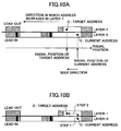
- the seek direction extends from the disc inner circumference to the outer circumference.
- a check is made as to whether the seek direction is the same as the direction in which the address increases in the layer LAYER-1. As shown in Fig. 10A , if the seek direction extends from the disc outer circumference to the inner circumference, the result of the check is affirmative, so that the procedure proceeds to step 423. As shown in Fig. 11A , on the other hand, if the seek direction extends from the disc inner circumference to the outer circumference, the result of the check is negative, and the procedure proceeds to step 421.
- the second scan path is selected as shown in Fig. 11B serving as a non-limiting example. That is, the target address is reached by performing (1) a coarse seek operation to the tentative target address (address F' in this example) (STEP 1), (2) a focus jump (STEP 2), and (3) a fine seek operation to the target address (STEP 3).
- the program corresponding to the flowchart of Fig. 9 may be performed by the CPU 40 in place of the program corresponding to the flowchart of Fig. 6 .
- the control apparatus is implemented based on steps 403 through 433 of Fig. 9 .
- the selection procedure in the program of the present invention is implemented by use of the program corresponding to the processes of steps 411 through 423 of Fig. 9 . Further, the processes of steps 411 through 423 shown in Fig. 9 achieve the selection process in the reproduction method of the present invention.
- the tentative target address is set at a position in the layer LAYER-0 that is displaced toward the outer circumference side from the radial position of the target address. If there is little risk of accessing an unrecorded area upon a focus jump, for example, there may be no need to displace the tentative target address purposefully.
- the optical disc conforms to the single-side two-layer DVD+R standard.
- This is only a non-limiting example, and the present invention is applicable to the next-generation single-side two-layer disc that is adapted to light having a wavelength of approximately 405 nm, for example.
- the program of the present invention is stored in the flash memory 39.
- the program may alternatively be stored in other recording medium such as a CD, magneto-optical disc, DVD, memory card, USB memory, flexible disc, etc.
- the program of the present invention is loaded to the flash memory 39 by use of a reproducing apparatus (or dedicated interface) adapted to such recording medium.
- the program of the present invention may be transferred to the flash memory 39 via a network such as a LAN, intranet, the Internet, etc. In other words, it suffices if the program of the present invention is loaded to the flash memory 39 in one way or another.
- the optical pickup apparatus is provided with a single semiconductor laser.
- the present invention may be applicable to a configuration in which a plurality of semiconductor lasers emit optical beams having different wavelengths.
- this configuration may include at least one of the semiconductor laser emitting an optical beam having a wavelength of approximately 405 nm, the semiconductor laser emitting an optical beam having a wavelength of approximately 660 nm, and the semiconductor laser emitting an optical beam having a wavelength of approximately 780 nm.
- the optical disc apparatus may be adapted to a plurality of types of optical discs conforming to different standards.
- at least one of the optical discs may be an optical disc having a plurality of recording layers.
- the reproduction method according to the present invention may be suited for a proper and stable reproduction of information recorded on an optical disc that has a plurality of recording layers with an unrecorded area and a recorded area being coexistent.
- the optical disc apparatus according to the present invention may be suited for a proper and stable reproduction of information recorded on an optical disc that has a plurality of recording layers with an unrecorded area and a recorded area being coexistent.
- the program and recording medium according to the present invention the reproduction method according to the present invention may be suited for a proper and stable reproduction of information recorded on an optical disc that has a plurality of recording layers with an unrecorded area and a recorded area being coexistent.
Landscapes
- Optical Recording Or Reproduction (AREA)
- Moving Of The Head For Recording And Reproducing By Optical Means (AREA)
Claims (16)
- Verfahren zur Wiedergabe von Information, die auf einer optischen Platte mit mehreren Aufzeichnungsschichten, einschließlich einer ersten Aufzeichnungsschicht (LAYER-0) und einer zweiten Aufzeichnungsschicht (LAYER-1), aufgezeichnet ist, umfassend die folgenden Schritte;
Zurückgreifen auf eine Aufzeichnungsreihenfolge der ersten und der zweiten Aufzeichnungsschicht, wonach Information in einem voraufzeichnungsbehafteten Bereich der optischen Platte aufgezeichnet ist; und
Auswählen eines Abtastweges auf der Grundlage der Aufzeichnungsreihenfolge, was die Durchführung einer Kontrolle einschließt, nämlich ob die erste Aufzeichnungsschicht (LAYER-0) eine aktuelle Aufzeichnungsschicht ist, aus einem ersten Abtastweg, bei dem vor einem Fokussprung keine Suchoperation erfolgt, und einem zweiten Abtastweg, bei dem vor einem Fokussprung eine Suchoperation erfolgt, um einen Lichtpunkt von einer ersten Adresse in der ersten Aufzeichnungsschicht zu einer zweiten Adresse in der zweiten Aufzeichnungsschicht zu führen, indem entlang des voraufzeichnungsbehafteten Bereichs in zumindest einer, nämlich der ersten und/oder der zweiten Aufzeichnungsschicht abgetastet wird, wobei die zweite Adresse eine Zieladresse ist, wo Wiedergabe erfolgen soll;
wobei der zweite Abtastweg ausgewählt wird, wenn die aktuelle Aufzeichnungsschicht die erste Aufzeichnungsschicht (LAYER-0) ist, und der erste Abtastweg ausgewählt wird, wenn die erste Aufzeichnungsschicht (LAYER-0) die Zielaufzeichnungsschicht, aber nicht die aktuelle Aufzeichnungsschicht ist. - Verfahren nach Anspruch 1, wobei der erste Abtastweg umfasst:einen Fokussprung von der ersten zur zweiten Aufzeichnungsschicht an der ersten Adresse; undeine Suchoperation bis zur zweiten Adresse in der zweiten Aufzeichnungsschicht nach dem Fokussprung,und der zweite Abtastweg umfasst:eine Suchoperation in der ersten Aufzeichnungsschicht von der ersten Adresse bis zu einer dritten Adresse, die sich in der ersten Aufzeichnungsschicht in Nachbarschaft zur zweiten Adresse in Bezug auf die radiale Richtung der optischen Platte befindet;einen Fokussprung von der ersten zur zweiten Aufzeichnungsschicht an der dritten Adresse; undeine Suchoperation bis zur zweiten Adresse in der zweiten Aufzeichnungsschicht nach dem Fokussprung.
- Verfahren nach Anspruch 2, wobei auf dem zweiten Abtastweg eine Richtung, die sich von der dritten Adresse zur zweiten Adresse in Bezug auf die radiale Richtung der optischen Platte erstreckt, eine Richtung ist, in der sich eine Adresse in der zweiten Aufzeichnungsschicht erhöht.
- Verfahren nach Anspruch 1, wobei der Schritt des Auswählens den ersten Abtastweg auswählt, wenn die zweite Aufzeichnungsschicht in der Reihenfolge der Aufzeichnung vor der ersten Aufzeichnungsschicht liegt.
- Verfahren nach Anspruch 1, wobei der Schritt des Auswählens den zweiten Abtastweg auswählt, wenn die erste Aufzeichnungsschicht in der Reihenfolge der Aufzeichnung vor der zweiten Aufzeichnungsschicht liegt.
- Verfahren nach Anspruch 1, wobei der Schritt des Auswählens den ersten Abtastweg auswählt, wenn die erste Aufzeichnungsschicht in der Reihenfolge der Aufzeichnung vor der zweiten Aufzeichnungsschicht liegt und wenn eine Richtung, die sich von der ersten Adresse zur zweiten Adresse in Bezug auf die radiale Richtung der optischen Platte erstreckt, eine Richtung ist, in der sich eine Adresse in der zweiten Aufzeichnungsschicht erhöht.
- Verfahren nach Anspruch 1, wobei der Schritt des Auswählens den zweiten Abtastweg auswählt, wenn die erste Aufzeichnungsschicht in der Reihenfolge der Aufzeichnung vor der zweiten Aufzeichnungsschicht liegt und wenn eine Richtung, die sich von der ersten Adresse zur zweiten Adresse in Bezug auf die radiale Richtung der optischen Platte erstreckt, einer Richtung entgegengesetzt ist, in der sich eine Adresse in der zweiten Aufzeichnungsschicht erhöht.
- Optische Plattenvorrichtung zur Wiedergabe von Information, die auf einer optischen Platte mit mehreren Aufzeichnungsschichten, einschließlich einer ersten Aufzeichnungsschicht (LAYER-0) und einer zweiten Aufzeichnungsschicht (LAYER-1), aufgezeichnet ist, umfassend:eine Lichtsensoreinheit, die dafür konfiguriert ist, einen Lichtpunkt auf einer Aufzeichnungsschicht, die aus den mehreren Aufzeichnungsschichten ausgewählt ist, zu bilden und Licht zu detektieren, das von der ausgewählten Aufzeichnungsschicht reflektiert wird;eine Steuereinheit, die dafür konfiguriert ist, die Lichtsensoreinheit so zu steuern, dass auf eine Aufzeichnungsreihenfolge der ersten und der zweiten Aufzeichnungsschicht zurückgegriffen wird, wonach Information in einem voraufzeichnungsbehafteten Bereich der optischen Platte aufgezeichnet ist, und dass ein Abtastweg auf der Grundlage der Aufzeichnungsreihenfolge ausgewählt wird, was die Durchführung einer Kontrolle einschließt, nämlich ob die erste Aufzeichnungsschicht (LAYER-0) eine aktuelle Aufzeichnungsschicht ist, aus einem ersten Abtastweg, bei dem vor einem Fokussprung keine Suchoperation erfolgt, und einem zweiten Abtastweg, bei dem vor einem Fokussprung eine Suchoperation erfolgt, um den Lichtpunkt von einer ersten Adresse in dem ersten Aufzeichnungsschicht zu einer zweiten Adresse in der zweiten Aufzeichnungsschicht zu führen, indem entlang des voraufzeichnungsbehafteten Bereichs in zumindest einer, nämlich der ersten und/oder der zweiten Aufzeichnungsschicht abgetastet wird, wobei die zweite Adresse eine Zieladresse ist, wo Wiedergabe erfolgen soll;wobei der zweite Abtastweg ausgewählt wird, wenn die aktuelle Aufzeichnungsschicht die erste Aufzeichnungsschicht (LAYER-0) ist, und der erste Abtastweg ausgewählt wird, wenn die erste Aufzeichnungsschicht (LAYER-0) die Zielaufzeichnungsschicht, aber nicht die aktuelle Aufzeichnungsschicht ist;und eine Verarbeitungseinheit, die dafür konfiguriert ist, Information unter Verwendung eines Signals wiederzugeben, das von der Lichtsensoreinheit ausgegeben wird.
- Optische Plattenvorrichtung nach Anspruch 8, wobei der erste Abtastweg umfasst:einen Fokussprung von der ersten zur zweiten Aufzeichnungsschicht an der ersten Adresse; undeine Suchoperation bis zur zweiten Adresse in der zweiten Aufzeichnungsschicht nach dem Fokussprung,und der zweite Abtastweg umfasst:eine Suchoperation in der ersten Aufzeichnungsschicht von der ersten Adresse bis zu einer dritten Adresse, die sich in der ersten Aufzeichnungsschicht in Nachbarschaft zur zweiten Adresse in Bezug auf die radiale Richtung der optischen Platte befindet;einen Fokussprung von der ersten zur zweiten Aufzeichnungsschicht an der dritten Adresse; undeine Suchoperation bis zur zweiten Adresse in der zweiten Aufzeichnungsschicht nach dem Fokussprung.
- Optische Plattenvorrichtung nach Anspruch 9, wobei auf dem zweiten Abtastweg eine Richtung, die sich von der dritten Adresse zur zweiten Adresse in Bezug auf die radiale Richtung der optischen Platte erstreckt, eine Richtung ist, in der sich eine Adresse in der zweiten Aufzeichnungsschicht erhöht.
- Optische Plattenvorrichtung nach Anspruch 8, wobei die Steuereinheit den ersten Abtastweg auswählt, wenn die zweite Aufzeichnungsschicht in der Reihenfolge der Aufzeichnung vor der ersten Aufzeichnungsschicht liegt.
- Optische Plattenvorrichtung nach Anspruch 8, wobei die Steuereinheit den zweiten Abtastpfad auswählt, wenn die erste Aufzeichnungsschicht in der Reihenfolge der Aufzeichnung vor der zweiten Aufzeichnungsschicht liegt.
- Optische Plattenvorrichtung nach Anspruch 8, wobei die Steuereinheit den ersten Abtastpfad, wenn die erste Aufzeichnungsschicht in der Reihenfolge der Aufzeichnung vor der zweiten Aufzeichnungsschicht, und wenn eine Richtung, die sich von der ersten Adresse zur zweiten Adresse in Bezug auf die radiale Richtung der optischen Platte erstreckt, eine Richtung ist, in der sich eine Adresse in der zweiten Aufzeichnungsschicht erhöht.
- Optische Plattenvorrichtung nach Anspruch 8, wobei die Steuereinheit den zweiten Abtastpfad auswählt, wenn die erste Aufzeichnungsschicht in der Reihenfolge der Aufzeichnung vor der zweiten Aufzeichnungsschicht und wenn eine Richtung, die sich von der ersten Adresse zur zweiten Adresse in Bezug auf die radiale Richtung der optischen Platte erstreckt, einer Richtung entgegengesetzt ist, in der sich eine Adresse in der zweiten Aufzeichnungsschicht erhöht.
- Programm, mit dem bewirkt werden kann, dass ein zur Steuerung dienender Computer in einer optischen Plattenvorrichtung Information wiedergibt, die auf einer optischen Platte mit mehreren Aufzeichnungsschichten, einschließlich einer ersten und einer zweiten Aufzeichnungsschicht, aufgezeichnet ist, umfassend Programmcodes, um zu bewirken, dass der zur Steuerung dienende Computer das Verfahren nach einem der Ansprüche 1 bis 7 durchführt.
- Computerlesbares Aufzeichnungsmedium mit einem darin verkörperten Programm, mit dem bewirkt werden kann, dass ein zur Steuerung dienender Computer in einer optischen Plattenvorrichtung Information wiedergibt, die auf einer optischen Platte mit mehreren Aufzeichnungsschichten, einschließlich einer ersten und einer zweiten Aufzeichnungsschicht, aufgezeichnet ist, wobei das Programm Programmcodes umfasst, um zu bewirken, dass der zur Steuerung dienende Computer das Verfahren nach einem der Ansprüche 1 bis 7 durchführt.
Applications Claiming Priority (2)
| Application Number | Priority Date | Filing Date | Title |
|---|---|---|---|
| JP2004302568A JP2006114169A (ja) | 2004-10-18 | 2004-10-18 | 再生方法、光ディスク装置、プログラム及び記録媒体 |
| PCT/JP2005/019350 WO2006043648A1 (en) | 2004-10-18 | 2005-10-14 | Performing error-free access operation on multi-layered disc |
Publications (3)
| Publication Number | Publication Date |
|---|---|
| EP1834323A1 EP1834323A1 (de) | 2007-09-19 |
| EP1834323A4 EP1834323A4 (de) | 2012-11-28 |
| EP1834323B1 true EP1834323B1 (de) | 2016-01-06 |
Family
ID=35432303
Family Applications (1)
| Application Number | Title | Priority Date | Filing Date |
|---|---|---|---|
| EP05795332.5A Expired - Lifetime EP1834323B1 (de) | 2004-10-18 | 2005-10-14 | Durchführen einer fehlerfreien zugriffsoperation auf einem mehrschichtigen datenträger |
Country Status (5)
| Country | Link |
|---|---|
| US (1) | US7990808B2 (de) |
| EP (1) | EP1834323B1 (de) |
| JP (1) | JP2006114169A (de) |
| CN (1) | CN101040331A (de) |
| WO (1) | WO2006043648A1 (de) |
Families Citing this family (5)
| Publication number | Priority date | Publication date | Assignee | Title |
|---|---|---|---|---|
| JP3594243B1 (ja) * | 2003-03-25 | 2004-11-24 | 株式会社リコー | 光情報記録方法、光情報記録装置、情報処理装置、光情報記録媒体 |
| JP2006114169A (ja) | 2004-10-18 | 2006-04-27 | Ricoh Co Ltd | 再生方法、光ディスク装置、プログラム及び記録媒体 |
| JP4942820B2 (ja) * | 2007-12-03 | 2012-05-30 | パイオニア株式会社 | 記録装置及び方法、並びにコンピュータプログラム |
| US20120127840A1 (en) * | 2009-07-17 | 2012-05-24 | Sharp Kabushiki Kaisha | Information recording medium, recording/reproducing device, recording/reproducing device control method, recording/reproducing device control program, and computer readable recording medium |
| US8385178B2 (en) * | 2010-12-23 | 2013-02-26 | General Electric Company | Multi-stage focus actuator and optical head |
Family Cites Families (17)
| Publication number | Priority date | Publication date | Assignee | Title |
|---|---|---|---|---|
| JPH08282675A (ja) | 1995-04-17 | 1996-10-29 | Honda Motor Co Ltd | 梱包ケース用のキャスタ |
| JP2000251271A (ja) * | 1999-02-25 | 2000-09-14 | Sony Corp | ディスクドライブ装置 |
| JP3860394B2 (ja) | 2000-06-20 | 2006-12-20 | 株式会社リコー | 情報再生方法及び情報再生装置 |
| JP2002008252A (ja) | 2000-06-22 | 2002-01-11 | Toshiba Corp | 光ディスク装置及び光ディスクアクセス制御方法 |
| JP4006184B2 (ja) | 2001-01-30 | 2007-11-14 | 株式会社リコー | 情報記録再生方法、情報記録再生装置、情報処理装置及びコンピュータ・プログラム |
| JP2002324363A (ja) | 2001-04-25 | 2002-11-08 | Ricoh Co Ltd | 情報記録再生装置 |
| JP3878442B2 (ja) | 2001-07-30 | 2007-02-07 | 株式会社リコー | 情報記録再生装置とプログラム |
| JP3886800B2 (ja) | 2001-12-19 | 2007-02-28 | 株式会社リコー | データ管理情報取得方法、情報再生装置、並びにデータ管理情報取得プログラム及び記録媒体 |
| JP4100913B2 (ja) | 2002-01-15 | 2008-06-11 | 株式会社リコー | 情報再生装置、データ管理情報取得方法、データ管理情報取得プログラム、記憶媒体、及び再生システム |
| JP2004005842A (ja) | 2002-05-31 | 2004-01-08 | Ricoh Co Ltd | 記録方法、記録媒体、プログラム及び情報記録媒体、並びに情報記録装置 |
| JP3772136B2 (ja) * | 2002-07-30 | 2006-05-10 | 株式会社東芝 | 光ディスク装置と光ディスク装置のアクセス方法 |
| JP4183553B2 (ja) | 2002-09-19 | 2008-11-19 | 株式会社リコー | 記録方法、プログラム及び記録媒体、並びに情報記録装置 |
| JP3867038B2 (ja) | 2002-10-23 | 2007-01-10 | 株式会社リコー | 情報記録装置と情報記録方法とプログラムと記録媒体 |
| JP3710790B2 (ja) | 2003-03-24 | 2005-10-26 | 株式会社リコー | 情報記録方法及びその装置 |
| KR100564618B1 (ko) * | 2004-03-11 | 2006-03-28 | 삼성전자주식회사 | 디스크 드라이브의 층간 탐색 방법 |
| JP4713839B2 (ja) * | 2004-03-17 | 2011-06-29 | 株式会社日立エルジーデータストレージ | 光ディスク装置及びそのフォーカスジャンプ制御方法 |
| JP2006114169A (ja) | 2004-10-18 | 2006-04-27 | Ricoh Co Ltd | 再生方法、光ディスク装置、プログラム及び記録媒体 |
-
2004
- 2004-10-18 JP JP2004302568A patent/JP2006114169A/ja active Pending
-
2005
- 2005-10-14 US US11/663,509 patent/US7990808B2/en not_active Expired - Fee Related
- 2005-10-14 WO PCT/JP2005/019350 patent/WO2006043648A1/en not_active Ceased
- 2005-10-14 CN CNA2005800354556A patent/CN101040331A/zh active Pending
- 2005-10-14 EP EP05795332.5A patent/EP1834323B1/de not_active Expired - Lifetime
Also Published As
| Publication number | Publication date |
|---|---|
| JP2006114169A (ja) | 2006-04-27 |
| US20080144455A1 (en) | 2008-06-19 |
| EP1834323A1 (de) | 2007-09-19 |
| EP1834323A4 (de) | 2012-11-28 |
| CN101040331A (zh) | 2007-09-19 |
| US7990808B2 (en) | 2011-08-02 |
| WO2006043648A1 (en) | 2006-04-27 |
Similar Documents
| Publication | Publication Date | Title |
|---|---|---|
| JPWO2002086873A1 (ja) | 光ディスクおよびそれを用いた情報記録/再生方法および情報記録/再生装置 | |
| US20100254252A1 (en) | Recording medium, recording apparatus and recording method | |
| JP2002352469A (ja) | 多層情報記録媒体及び情報記録再生装置 | |
| JP4395477B2 (ja) | 情報記録媒体、並びに情報記録装置及び方法 | |
| US7539114B2 (en) | Recording apparatus and recording method | |
| US7990808B2 (en) | Performing error-free access operation on multi-layered disc | |
| US7995438B2 (en) | Reproducing method, optical disk apparatus, program and computer readable information recording medium | |
| JP2005267704A (ja) | 光ディスク装置及びそのフォーカスジャンプ制御方法 | |
| WO2005001823A1 (en) | Information storage medium and method and apparatus for recording/reproducing data | |
| JP2007048404A (ja) | 情報記録媒体、情報処理装置及び方法、並びに、記録又は再生を行う処理制御用のコンピュータプログラム | |
| JP4197170B2 (ja) | 記録方法、情報記録装置、プログラム及び記録媒体 | |
| US8094526B2 (en) | Information recording device and method, and computer program | |
| EP1880380B1 (de) | Aufzeichnungsverfahren für optische datenträger, optische datenträgereinrichtung, programm und aufzeichnungsmedium | |
| JP4315253B2 (ja) | 情報記録媒体 | |
| JP4810572B2 (ja) | 記録可能型情報記録媒体、情報記録装置および情報記録方法 | |
| KR100662592B1 (ko) | 광 디스크 장치 및 그 제어 방법 | |
| US20080267035A1 (en) | Information Recording Medium | |
| JP2006313600A (ja) | 記録方法、プログラム及び記録媒体、並びに情報記録装置 | |
| JP2005346818A (ja) | 光ディスク記録方法および光ディスク記録装置 | |
| KR20100017674A (ko) | 광 드라이브의 디스크 기동 시간 | |
| JP2009037704A (ja) | 情報記録媒体、情報記録装置、情報記録方法、情報再生装置、情報再生方法 | |
| CN101377931A (zh) | 数据可写入地址定位方法以及光学数据记录装置 | |
| JP2005346785A (ja) | 記録方法、情報記録媒体、再生方法、情報記録装置及び情報再生装置 | |
| JP2008135111A (ja) | 光ディスク装置および光ディスク再生方法 | |
| JP2008165882A (ja) | 光ディスク装置及びその制御方法 |
Legal Events
| Date | Code | Title | Description |
|---|---|---|---|
| PUAI | Public reference made under article 153(3) epc to a published international application that has entered the european phase |
Free format text: ORIGINAL CODE: 0009012 |
|
| 17P | Request for examination filed |
Effective date: 20070321 |
|
| AK | Designated contracting states |
Kind code of ref document: A1 Designated state(s): DE ES FR GB IT NL |
|
| DAX | Request for extension of the european patent (deleted) | ||
| RBV | Designated contracting states (corrected) |
Designated state(s): DE ES FR GB IT NL |
|
| RIC1 | Information provided on ipc code assigned before grant |
Ipc: G11B 27/10 20060101AFI20091111BHEP Ipc: G11B 7/085 20060101ALI20091111BHEP |
|
| RIC1 | Information provided on ipc code assigned before grant |
Ipc: G11B 27/10 20060101AFI20120412BHEP Ipc: G11B 7/085 20060101ALI20120412BHEP |
|
| A4 | Supplementary search report drawn up and despatched |
Effective date: 20121030 |
|
| 17Q | First examination report despatched |
Effective date: 20130312 |
|
| REG | Reference to a national code |
Ref country code: DE Ref legal event code: R079 Ref document number: 602005048254 Country of ref document: DE Free format text: PREVIOUS MAIN CLASS: G11B0007085000 Ipc: G11B0020100000 |
|
| GRAJ | Information related to disapproval of communication of intention to grant by the applicant or resumption of examination proceedings by the epo deleted |
Free format text: ORIGINAL CODE: EPIDOSDIGR1 |
|
| GRAP | Despatch of communication of intention to grant a patent |
Free format text: ORIGINAL CODE: EPIDOSNIGR1 |
|
| GRAP | Despatch of communication of intention to grant a patent |
Free format text: ORIGINAL CODE: EPIDOSNIGR1 |
|
| RIC1 | Information provided on ipc code assigned before grant |
Ipc: G11B 20/10 20060101AFI20150622BHEP Ipc: G11B 20/12 20060101ALI20150622BHEP Ipc: G11B 7/085 20060101ALI20150622BHEP Ipc: G11B 27/10 20060101ALI20150622BHEP Ipc: G11B 7/00 20060101ALI20150622BHEP |
|
| INTG | Intention to grant announced |
Effective date: 20150716 |
|
| GRAS | Grant fee paid |
Free format text: ORIGINAL CODE: EPIDOSNIGR3 |
|
| GRAA | (expected) grant |
Free format text: ORIGINAL CODE: 0009210 |
|
| AK | Designated contracting states |
Kind code of ref document: B1 Designated state(s): DE ES FR GB IT NL |
|
| REG | Reference to a national code |
Ref country code: GB Ref legal event code: FG4D |
|
| REG | Reference to a national code |
Ref country code: DE Ref legal event code: R096 Ref document number: 602005048254 Country of ref document: DE |
|
| REG | Reference to a national code |
Ref country code: NL Ref legal event code: MP Effective date: 20160106 |
|
| PG25 | Lapsed in a contracting state [announced via postgrant information from national office to epo] |
Ref country code: NL Free format text: LAPSE BECAUSE OF FAILURE TO SUBMIT A TRANSLATION OF THE DESCRIPTION OR TO PAY THE FEE WITHIN THE PRESCRIBED TIME-LIMIT Effective date: 20160106 |
|
| PG25 | Lapsed in a contracting state [announced via postgrant information from national office to epo] |
Ref country code: ES Free format text: LAPSE BECAUSE OF FAILURE TO SUBMIT A TRANSLATION OF THE DESCRIPTION OR TO PAY THE FEE WITHIN THE PRESCRIBED TIME-LIMIT Effective date: 20160106 Ref country code: IT Free format text: LAPSE BECAUSE OF FAILURE TO SUBMIT A TRANSLATION OF THE DESCRIPTION OR TO PAY THE FEE WITHIN THE PRESCRIBED TIME-LIMIT Effective date: 20160106 |
|
| REG | Reference to a national code |
Ref country code: DE Ref legal event code: R097 Ref document number: 602005048254 Country of ref document: DE |
|
| REG | Reference to a national code |
Ref country code: FR Ref legal event code: PLFP Year of fee payment: 12 |
|
| PLBE | No opposition filed within time limit |
Free format text: ORIGINAL CODE: 0009261 |
|
| STAA | Information on the status of an ep patent application or granted ep patent |
Free format text: STATUS: NO OPPOSITION FILED WITHIN TIME LIMIT |
|
| 26N | No opposition filed |
Effective date: 20161007 |
|
| REG | Reference to a national code |
Ref country code: FR Ref legal event code: PLFP Year of fee payment: 13 |
|
| REG | Reference to a national code |
Ref country code: FR Ref legal event code: PLFP Year of fee payment: 14 |
|
| PGFP | Annual fee paid to national office [announced via postgrant information from national office to epo] |
Ref country code: DE Payment date: 20191021 Year of fee payment: 15 |
|
| PGFP | Annual fee paid to national office [announced via postgrant information from national office to epo] |
Ref country code: FR Payment date: 20191028 Year of fee payment: 15 |
|
| PGFP | Annual fee paid to national office [announced via postgrant information from national office to epo] |
Ref country code: GB Payment date: 20191021 Year of fee payment: 15 |
|
| REG | Reference to a national code |
Ref country code: DE Ref legal event code: R119 Ref document number: 602005048254 Country of ref document: DE |
|
| GBPC | Gb: european patent ceased through non-payment of renewal fee |
Effective date: 20201014 |
|
| PG25 | Lapsed in a contracting state [announced via postgrant information from national office to epo] |
Ref country code: FR Free format text: LAPSE BECAUSE OF NON-PAYMENT OF DUE FEES Effective date: 20201031 Ref country code: DE Free format text: LAPSE BECAUSE OF NON-PAYMENT OF DUE FEES Effective date: 20210501 |
|
| PG25 | Lapsed in a contracting state [announced via postgrant information from national office to epo] |
Ref country code: GB Free format text: LAPSE BECAUSE OF NON-PAYMENT OF DUE FEES Effective date: 20201014 |