EP1834713A1 - Appareil pour la fabrication de tôles ondulées - Google Patents
Appareil pour la fabrication de tôles ondulées Download PDFInfo
- Publication number
- EP1834713A1 EP1834713A1 EP07005164A EP07005164A EP1834713A1 EP 1834713 A1 EP1834713 A1 EP 1834713A1 EP 07005164 A EP07005164 A EP 07005164A EP 07005164 A EP07005164 A EP 07005164A EP 1834713 A1 EP1834713 A1 EP 1834713A1
- Authority
- EP
- European Patent Office
- Prior art keywords
- corrugated sheet
- distance
- axis
- roll pair
- forming
- Prior art date
- Legal status (The legal status is an assumption and is not a legal conclusion. Google has not performed a legal analysis and makes no representation as to the accuracy of the status listed.)
- Withdrawn
Links
Images





Classifications
-
- B—PERFORMING OPERATIONS; TRANSPORTING
- B21—MECHANICAL METAL-WORKING WITHOUT ESSENTIALLY REMOVING MATERIAL; PUNCHING METAL
- B21D—WORKING OR PROCESSING OF SHEET METAL OR METAL TUBES, RODS OR PROFILES WITHOUT ESSENTIALLY REMOVING MATERIAL; PUNCHING METAL
- B21D13/00—Corrugating sheet metal, rods or profiles; Bending sheet metal, rods or profiles into wave form
- B21D13/04—Corrugating sheet metal, rods or profiles; Bending sheet metal, rods or profiles into wave form by rolling
-
- F—MECHANICAL ENGINEERING; LIGHTING; HEATING; WEAPONS; BLASTING
- F01—MACHINES OR ENGINES IN GENERAL; ENGINE PLANTS IN GENERAL; STEAM ENGINES
- F01N—GAS-FLOW SILENCERS OR EXHAUST APPARATUS FOR MACHINES OR ENGINES IN GENERAL; GAS-FLOW SILENCERS OR EXHAUST APPARATUS FOR INTERNAL-COMBUSTION ENGINES
- F01N3/00—Exhaust or silencing apparatus having means for purifying, rendering innocuous, or otherwise treating exhaust
- F01N3/08—Exhaust or silencing apparatus having means for purifying, rendering innocuous, or otherwise treating exhaust for rendering innocuous
- F01N3/10—Exhaust or silencing apparatus having means for purifying, rendering innocuous, or otherwise treating exhaust for rendering innocuous by thermal or catalytic conversion of noxious components of exhaust
- F01N3/24—Exhaust or silencing apparatus having means for purifying, rendering innocuous, or otherwise treating exhaust for rendering innocuous by thermal or catalytic conversion of noxious components of exhaust characterised by constructional aspects of converting apparatus
- F01N3/28—Construction of catalytic reactors
- F01N3/2803—Construction of catalytic reactors characterised by structure, by material or by manufacturing of catalyst support
- F01N3/2807—Metal other than sintered metal
- F01N3/281—Metallic honeycomb monoliths made of stacked or rolled sheets, foils or plates
- F01N3/2814—Metallic honeycomb monoliths made of stacked or rolled sheets, foils or plates all sheets, plates or foils being corrugated
-
- F—MECHANICAL ENGINEERING; LIGHTING; HEATING; WEAPONS; BLASTING
- F01—MACHINES OR ENGINES IN GENERAL; ENGINE PLANTS IN GENERAL; STEAM ENGINES
- F01N—GAS-FLOW SILENCERS OR EXHAUST APPARATUS FOR MACHINES OR ENGINES IN GENERAL; GAS-FLOW SILENCERS OR EXHAUST APPARATUS FOR INTERNAL-COMBUSTION ENGINES
- F01N2330/00—Structure of catalyst support or particle filter
- F01N2330/02—Metallic plates or honeycombs, e.g. superposed or rolled-up corrugated or otherwise deformed sheet metal
- F01N2330/04—Methods of manufacturing
Definitions
- the present invention generally relates to a corrugated sheet used for a metal carrier that purifies exhaust gas discharged from an internal combustion engine of, for example, a vehicle.
- the present invention relates to an apparatus for manufacturing a corrugated sheet having a part where the height of corrugations gradually decreases.
- a vehicle having an internal combustion engine employs a metal carrier serving as a catalytic converter for removing noxious components from exhaust gas.
- the metal carrier is manufactured by coiling a corrugated sheet with a flat sheet into a metallic honeycomb core having a honeycomb sectional shape and by inserting the metallic honeycomb core into a metallic cylinder.
- the manufacturing method of the above-mentioned related art causes a step-like difference at a spiral end of the core due to the thickness of the overlapped corrugated and flat sheets.
- the step-like difference causes a local deformation that may be propagated toward the center of the core, to make an internal shape of the core deviate from a designed shape.
- the improper internal shape of the core increases excessive catalytic fillets during a catalytic coating process. Such excessive catalytic fillets increase air-flow resistance.
- the improper internal shape and excessive catalytic fillets of the core cause another problem of reducing a volumetric surface area of the corrugated sheet that contacts exhaust gas.
- An object of the present invention is to provide an apparatus for manufacturing a corrugated sheet that is appropriate for reducing a step-like difference that may be caused at a winding end when the corrugated sheet is rolled up with a flat sheet into a honeycomb core.
- a first aspect of the present invention provides an apparatus for manufacturing a corrugated sheet.
- the corrugated sheet manufacturing apparatus includes: a forming roll pair configured to roll a band material into a first-shape corrugated sheet; a pitch-shortening roll pair configured to shorten pitches of the first-shape corrugated sheet into a second-shape corrugated sheet; a shaping roll pair configured to widen pitches of the second-shape corrugated sheet into an objective corrugated sheet; a distance changer configured to change an axis-to-axis distance of the forming roll pair; a detector configured to detect a quantity of the first-shape corrugated sheet delivered from the forming roll pair; and a controller configured to control, when the detected quantity of the first-shape corrugated sheet is equal to a predetermined value, the distance changer so that the axis-to-axis distance of the forming roll pair is changed from a first distance to a second distance that is larger than the first distance.
- a second aspect of the present invention provides an apparatus for manufacturing a corrugated sheet.
- the corrugated sheet manufacturing apparatus includes: a forming roll pair configured to form a band material into a first-shape corrugated sheet; a pitch-shortening roll pair configured to shorten pitches of the first-shape corrugated sheet into an intermediate-shape corrugated sheet with adjacent ridges of the intermediate-shape corrugated sheet being in contact with each other, and then, separate the adjacent ridges of the intermediate-shape corrugated sheet from each other into a second-shape corrugated sheet whose pitches are wider than those of the intermediate-shape corrugated sheet; a shaping roll pair configured to widen each pitch between the adjacent ridges of the second-shape corrugated sheet into an objective corrugated sheet; a distance changer configured to change an axis-to-axis distance of the forming roll pair; a detector configured to detect a quantity of the first-shape corrugated sheet delivered from the
- Figures 1A and 1B are sectional views showing forming rolls of the apparatus
- Fig. 2 is a partly sectioned perspective view showing the forming rolls
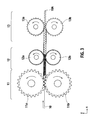
- Fig. 3 is a view generally showing roll pairs installed in the apparatus
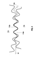
- Figs. 4 to 6 are enlarged views partly showing the roll pairs.
- the apparatus 100 includes a forming roll unit 11, a pitch-shortening roll unit 12, and a shaping roll unit 13.
- a supply roll (not shown) around which a band material 10 is wound.
- the band material 10 is drawn from the supply roll by a feed roll (not shown) and is continuously fed to the forming roll unit 11.
- a feed roll (not shown) and is continuously fed to the forming roll unit 11.
- mechanisms for supporting and driving rolls are omitted.
- the forming roll unit 11 includes a pair of forming rolls 11a and 11b that are vertically arranged and synchronously turned.
- the surface of the forming roll 11 a (11b) has forming teeth 110a (110b) as shown in Fig. 4.
- the teeth 110a and 110b engage with each other with a gap between them, and the forming rolls 11a and 11b are turned in an arrow direction (Fig. 3) while the band material 10 is being fed between the teeth 110a and 110b, to form the band material 10 into a corrugated sheet 10A having a first waveshape shown in Fig. 4.
- the teeth 110a and 110b have a height (amplitude) lower than a target height and a pitch (wavelength) wider than a target pitch.
- the forming roll 11 a is at a reference position with the teeth 110a and 110b meshing each other at a reference first axis-to-axis distance d1.
- the forming roll unit 11 is supported with a forming roll support 140 having a distance adjusting mechanism that adjusts the axis-to-axis distance of the forming rolls 11 a and 11b.
- the pitch-shortening roll unit 12 includes pitch-shortening rolls 12a and 12b that are vertically arranged and synchronously turned.
- the surface of the roll 12a (12b) has forming teeth 120a (120b) as shown in Fig. 5.
- the corrugated sheet 10A fed from the upstream forming roll unit 11 is temporarily stopped at the entrance of the pitch-shortening roll unit 12, and therefore, adjacent ridges of the corrugated sheet 10A are made in contact with each other to form an intermediate waveshape. In the intermediate waveshape, each ridge of the corrugated sheet 10A is semicircular. Thereafter, the pitch-shortening rolls 12a and 12b are turned in an arrow direction (Fig.
- the corrugated sheet 10A with separated ridges has a second waveshape whose pitches are wider than those of the intermediate waveshape.
- the corrugated sheet 10A will be deformed. According to the embodiment, the ridges of the corrugated sheet 10A are entirely held with the valleys of the teeth 120a and 120b as shown in Fig. 5, and therefore, the corrugated sheet 10A will not deform.
- the shaping roll unit 13 includes shaping rolls 13a and 13b that are vertically arranged and synchronously turned.
- the surface of the shaping roll 13a (13b) has shaping teeth 130a (130b) as shown in Fig. 6. Ridges of the shaping teeth 130a and 130b enter between adjacent ridges of the corrugated sheet 10A having the second waveshape and stretches the corrugated sheet 10A, to widen the pitches of the corrugated sheet 10A.
- the shaping roll unit 13 is set to stretch the corrugated sheet 10A so that the corrugated sheet 10A may have pitches that are wider than target pitches.
- the widened pitches thereof become shorter due to the resilience thereof, to have a target waveshape.
- guides are arranged to prevent the corrugated sheet 10A from obliquely traveling in thickness and width directions and to release the corrugated sheet 10A from the teeth 110a, 110b, 120a, 120b, 130a, and 130b.
- a driving mechanism for the forming roll unit 11 will be explained with reference to Figs. 1A, 1B, and 2.
- the forming roll unit 11 includes the forming rolls 11a and 11b that are supported with the support 140.
- the support 140 includes a base 141 and a pair of roll stands 142 and 143 that are arranged on the base 141 at a predetermined interval.
- the roll stand 142 (143) has a stand recess 144 (145) into which the forming rolls 11a and 11b are vertically inserted.
- the forming roll 11b has a roll shaft 11 b whose protruding ends are supported with bearing units 146 and 147, respectively.
- the bearing unit 146 (147) is arranged in a bearing frame 148 (149).
- the bearing frame 148 (149) is arranged in the stand recess 144 (145). The position of the forming roll 11b is fixed.
- the forming roll 11a has a roll shaft 111 a whose protruding ends are supported with bearing units 150 and 151, respectively.
- the bearing unit 150 (151) is arranged in a bearing frame 152 (153).
- the bearing frame 152 (153) is arranged in the stand recess 144 (145).
- the forming roll 11a is movable by motors (to be explained later) in a vertical direction.
- the stand recess 144 (145) is covered with a shaft support plate 154 (155).
- a shaft support plate 154 (155) At the center of the shaft support plate 154 (155), there is a through hole provided with a nut 154a (155a). The nut 154a (155a) engages with a thread of a drive shaft 158 (159) connected to the motor.
- the bearing box 156 engages with a pull disk 158a (159a) arranged at an end of the drive shaft 158 (159).
- the pull disk 158a (159a) is rotatable with respect to the drive shaft 158 (159). Accordingly, when the drive shaft 158 (159) is turned, the pull disk 158a (159a) does not turn together with the drive shaft. Instead, the pull disk 158a (159a) ascends or descends together with the bearing box 156 (157).
- the axis-to-axis distance of the forming rolls 11a and 11b is changeable by the motors 160 and 161.
- the motors 160 and 161 are fixed to a top support 112.
- the motor 160 (161) has a motor shaft 162 (163) whose end is provided with a female coupling 162a (163a).
- the female coupling 162a (163a) has an internal long hole of quadrangle cross section engaging with a protrusion 158b (159b) having a similar quadrangle cross section formed at the top of the drive shaft 158 (159).
- the motors 160 and 161 are driven under the control of a controller (ECU) 117.
- ECU controller
- torque is transmitted to the protrusion 158b (159b) engaging with the female coupling 162a (163a) of the drive shaft 158 (159), to turn the drive shaft 158 (159).
- the forming roll 11a has an encoder 113 for detecting the number of turns of the roll shaft 111a.
- the encoder 113 includes a pin 114 arranged at an end of the roll shaft 111a, a photodetector 115 attached to a stand 116, and a light source (not shown) arranged at a position facing the photodetector 115 with the pin 114 between the light source and the photodetector 115.
- the ECU 117 may be a microcomputer including, for example, a central processing unit (CPU), a random access memory (RAM), a read-only memory (ROM), and an input/output (I/O) interface.
- the ECU 117 may be made of a plurality of microcomputers.
- the ECU 117 may be configured to control a variety of tasks in addition to the task of changing the axis-to-axis distance of the forming roll unit 11.
- the ECU 117 finds the number of turns of the forming rolls 11a and 11 b from an electric signal provided by the encoder 113. If the number of turns is equal to a predetermined number r1, the ECU 117 drives the motors 160 and 161 to turn the drive shafts 162 and 163 in a counterclockwise direction, thereby gradually lifting the bearing frames 152 and 153 until the axis-to-axis distance of the forming rolls 11a and 11b changes from the reference first distance d1 to the second distance d2 that is larger than the distance d1.
- the ECU 117 drives the motors 160 and 161 to turn the drive shafts 162 and 163 in a clockwise direction, thereby gradually lowering the bearing frames 152 and 153 until the axis-to-axis distance of the forming rolls 11a and 11b becomes the first distance d1.
- the motors 160 and 161 are driven to lift the forming roll 11a from the reference position, and a flat band material 10 is passed through the forming roll unit 11 and pitch-shortening roll unit 12 up to the vicinity of the entrance of the shaping roll unit 13. Then, the motors 160 and 161 are driven to lower the forming roll 11 a until the axis-to-axis distance of the forming rolls 11a and 11b becomes the first distance d1. Thereafter, the forming rolls 11a and 11b are driven in the arrow direction shown in Fig. Fig. 3. As a result, the band material 10 is formed into a corrugated sheet 10A having a first waveshape as shown in Fig. 4. This is a first forming process. At this time, the pitch-shortening roll unit 12 and shaping roll unit 13 are stopped.
- the corrugated sheet 10A having the first waveshape reaches the pitch-shortening roll unit 12 and is blocked between the pitch-shortening rolls 12a and 12b.
- the forming rolls 11 a and 11b are continuously driven, so that the corrugated sheet 10A having the first waveshape is temporarily stopped at the entrance of the pitch-shortening roll unit 12 and adjacent ridges of the first waveshape are pressed to each other to form an intermediate waveshape. This is a pitch-shortening process.
- the pitch-shortening rolls 12a and 12b may be turned in the arrow direction (Fig. 3) by a predetermined angle, so that the teeth 120a and 120b of the rolls 12a and 12b may engage with ridges of the intermediate waveshape.
- the forming rolls 11a and 11b are continuously driven, and the intermediate waveshape is formed between the forming roll unit 11 and the pitch-shortening roll unit 12.
- the intermediate waveshape is formed to reach the exit of the forming roll unit 11, the forming roll unit 11, pitch-shortening roll unit 12, and shaping roll unit 13 are synchronously driven to deliver the corrugated sheet 10A ridge by ridge toward the downstream side.
- the forming roll unit 11 and the pitch-shortening roll unit 12 are synchronously driven to deliver the corrugated sheet 10A ridge by ridge toward the downstream side.
- Ridges of the first waveshape discharged from the forming roll unit 11 are sequentially brought close to each other between the forming roll unit 11 and the pitch-shortening roll unit 12 into ridges of the intermediate waveshape.
- ridges of the teeth 120a and 120b of the pitch-shortening rolls 12a and 12b enter between the ridges of the corrugated sheet 10A having the intermediate waveshape as shown in Fig. 5.
- valleys of the teeth 120a and 120b entirely hold the ridges of the corrugated sheet 10A and separate adjacent ridges of the corrugated sheet 10A from each other, to form a second waveshape whose pitches are wider than those of the intermediate waveshape. This is a second forming process.
- the corrugated sheet 10A having the second waveshape is stretched by the teeth 130a and 130b of the shaping rolls 13a and 13b, to widen the pitches of the second waveshape as shown in Fig. 6.
- the widened pitches of the corrugated sheet 10A contract due to resilience to form an objective waveshape. This is a third forming process.
- the ECU 117 sets the forming roll 11a at a normal position where the axis-to-axis distance of the forming roll unit 11 is the first distance d1 to produce a corrugated sheet 10A having a normal height.
- the ECU 117 receives an electric signal from the encoder 113, and according to the electric signal, calculates the number of turns of the forming rolls 11a and 11b.
- the ECU 117 drives the motors 160 and 161 in such a way as to turn the drive shafts 162 and 163 in a counterclockwise direction. Then, the bearing frames 152 and 153 gradually ascend until the axis-to-axis distance of the forming rolls 11a and 11b changes from the first distance d1 to the second distance d2 that is larger than the first distance d1.
- the ECU 117 drives the motors 160 and 161 in such a way as to turn the drive shafts 162 and 163 in a clockwise direction.
- the bearing frames 152 and 153 gradually descend until the axis-to-axis distance of the forming rolls 11a and 11b reaches the first distance d1.
- the embodiment gradually extends the axis-to-axis distance of the forming rolls 11a and 11b from the first distance d1 to the second distance d2, and thereafter, gradually reduces the axis-to-axis distance from the second distance d2 to the first distance d1, thereby forming a part in the corrugated sheet 10A where the height of corrugations of the corrugated sheet 10A gradually decreases from a standard height and then gradually increases to the standard height.
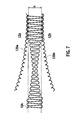
- Figure 7 is an enlarged view showing the entrance of the pitch-shortening roll unit 12.
- Fig. 7 shows a part of the corrugated sheet 10A where the height of corrugations gradually decreases from and increases to a normal height.
- a part of the corrugated sheet 10A having the normal corrugation height is caught by the teeth 120a and 120b of the pitch-shortening rolls 12a and 12b, and therefore, is pitch-shortened.
- a part of the corrugated sheet 10A where the height of corrugations gradually decreases and becomes smaller than a gap h set between the teeth 120a and 120b is not caught by the teeth 120a and 120b of the rolls 12a and 12b. This part, thus, passes between the pitch-shortening rolls 12a and 12b without being pitch-shortened.
- Fig. 7 the part where the height of corrugations gradually lowers and the part where the same gradually increases are depicted shorter than actual ones, for the sake of easy understanding.
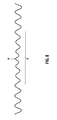
- Figure 8 shows the corrugated sheet 10A delivered from the pitch-shortening roll unit 12.
- S represents the part where the height of corrugations gradually lowers and increases.
- the part S of the corrugated sheet 10A is also not caught by the teeth 130a and 130b of the shaping rolls 13a and 13b, and therefore, is passed as it is between the rolls 13a and 13b.
- the corrugated sheet 10A delivered from the shaping roll unit 13 is cut by a cutter (not shown) at a location "a" where the corrugation height of the corrugated sheet 10A is minimum.
- the lowest corrugation height location "a" in the continuous corrugated sheet 10A can be identified according to the number of turns of the forming rolls 11a and 11b and a distance from the forming roll unit 11 to the cutter (not shown).
- the location "a” corresponds to a time when the number of turns of the forming rolls 11a and 11 b becomes r2 to return the axis-to-axis distance of the forming rolls 11a and 11 b to the first distance d1. From this time, the number of turns of the forming rolls 11a and 11b is counted to calculate a length of the corrugated sheet 10A discharged from the forming roll unit 11.
- the corrugated sheet 10A is cut by the cutter.
- the corrugated sheet 10A can be cut at the location "a" where the corrugation height of the corrugated sheet 10A is lowest.
- the corrugated sheet 10A is again cut, to provide a corrugated sheet product having an end part where the corrugation height of the product gradually decreases.
- the apparatus according to the embodiment can continuously provide a corrugated sheet, and therefore, is helpful to realize a continuous manufacturing line.
- the corrugated sheet 10A produced by the apparatus of the embodiment contains a part where the corrugation height thereof gradually decreases and a part where the corrugation height thereof gradually increases.
- Such a corrugated sheet 10A is cut at a lowest height location "a" to simultaneously provide two corrugated sheet products with one end involving gradually attenuating corrugations. Accordingly, the embodiment can improve the yield of corrugated sheet products.
- FIG. 9 is a perspective view showing a metal carrier according to an embodiment of the present invention.
- the metal carrier 1 has a core.
- the core is made of a corrugated sheet 2 (10A of the above-mentioned embodiment) made of a thin metal sheet spiraled with a flat sheet (or a corrugated sheet having small corrugations) 3.
- the core is covered with a soldering foil and is inserted into a metal cylinder 4.
- the cylinder 4 containing the core is heated in a vacuum, to diffuse and join the corrugated sheet 2 and flat sheet 3 with each other. At this time, the soldering foil joins with the cylinder 4, to form the metal carrier 1.
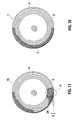
- Figure 10 is a front view showing a metal carrier 1 manufactured according to an embodiment of the present invention
- Fig. 11 is a front view showing a metal carrier according to a related art.
- a corrugated sheet 2A is coiled with a flat sheet 3, to form a core.
- the core has a step-like difference H at a finishing end of the coiled sheets.
- the difference H corresponds to the height of corrugations of the corrugated sheet 2A.
- the difference H locally deforms the core in an area "A" shown in Fig. 11.
- a corrugated sheet 2 coiled with a flat sheet 3 forms no step-like difference at a finishing end of the core because the height of corrugations at a trailing end of the corrugated sheet 2 gradually decreases.
- an internal shape of the metal carrier has a designed shape. Namely, the metal core 1 manufactured according to the present invention with the core inserted into the cylinder 4 involves no deformation.
- the metal carrier 1 according to the present invention After coated with a catalyst, the metal carrier 1 according to the present invention has no excessive catalytic fillets, and therefore, achieves low air-flow resistance. Namely, the catalyst-coated corrugated sheet in the metal carrier 1 according to the present invention has a required surface area per unit volume, to achieve a designed purifying ability.
- a metal carrier with a corrugated sheet having high corrugations according to an embodiment of the present invention can further improve a purifying ability compared with existing ones.
Landscapes
- Engineering & Computer Science (AREA)
- Chemical & Material Sciences (AREA)
- Chemical Kinetics & Catalysis (AREA)
- Mechanical Engineering (AREA)
- Health & Medical Sciences (AREA)
- Toxicology (AREA)
- Combustion & Propulsion (AREA)
- General Engineering & Computer Science (AREA)
- Catalysts (AREA)
- Shaping Metal By Deep-Drawing, Or The Like (AREA)
- Exhaust Gas After Treatment (AREA)
Applications Claiming Priority (1)
| Application Number | Priority Date | Filing Date | Title |
|---|---|---|---|
| JP2006072745A JP2007245199A (ja) | 2006-03-16 | 2006-03-16 | 波板の製造装置 |
Publications (1)
| Publication Number | Publication Date |
|---|---|
| EP1834713A1 true EP1834713A1 (fr) | 2007-09-19 |
Family
ID=38214470
Family Applications (1)
| Application Number | Title | Priority Date | Filing Date |
|---|---|---|---|
| EP07005164A Withdrawn EP1834713A1 (fr) | 2006-03-16 | 2007-03-13 | Appareil pour la fabrication de tôles ondulées |
Country Status (4)
| Country | Link |
|---|---|
| US (1) | US20070215286A1 (fr) |
| EP (1) | EP1834713A1 (fr) |
| JP (1) | JP2007245199A (fr) |
| CN (1) | CN101053882A (fr) |
Cited By (3)
| Publication number | Priority date | Publication date | Assignee | Title |
|---|---|---|---|---|
| AT512173B1 (de) * | 2012-05-11 | 2013-06-15 | Haboeck Herwig | Walzvorrichtung zur Herstellung von gewellten Platten |
| CN110202812A (zh) * | 2019-05-10 | 2019-09-06 | 国家能源投资集团有限责任公司 | 热塑性芯材的生产方法和生产设备 |
| DE102018214926A1 (de) * | 2018-09-03 | 2020-03-05 | Continental Automotive Gmbh | Wabenkörper für die Nachbehandlung von Abgasen |
Families Citing this family (6)
| Publication number | Priority date | Publication date | Assignee | Title |
|---|---|---|---|---|
| CN102527798A (zh) * | 2011-12-23 | 2012-07-04 | 浙江天泽环境科技有限公司 | 金属载体波纹带成型装置 |
| CN102744308A (zh) * | 2012-06-11 | 2012-10-24 | 丁胜康 | 一种多用式金属蜂窝载体波带压波装置 |
| CN103042083A (zh) * | 2012-12-10 | 2013-04-17 | 浙江达峰汽车技术有限公司 | 波纹板直接成型机 |
| CN103143594B (zh) * | 2013-03-01 | 2015-01-28 | 佛山市森科能源科技开发有限公司 | 一种自动调节压料厚度的板材压料成型装置 |
| CN103464580A (zh) * | 2013-08-30 | 2013-12-25 | 南京高一智光电有限公司 | 一种应用于导光板制造的间隙调整装置 |
| DE102015111571A1 (de) * | 2015-07-16 | 2017-01-19 | Dbk David + Baader Gmbh | Verfahren zum Herstellen eines Wellrippenelementes, Wellrippenelement und Heizregister |
Citations (6)
| Publication number | Priority date | Publication date | Assignee | Title |
|---|---|---|---|---|
| US5207083A (en) * | 1991-12-06 | 1993-05-04 | General Motors Corporation | Method of controlling the length of corrugated fins |
| JPH07299523A (ja) * | 1994-05-02 | 1995-11-14 | Nippondenso Co Ltd | 連続波状体の成形装置 |
| EP0775540A1 (fr) * | 1995-11-27 | 1997-05-28 | Ford Motor Company | Machine de formage d'une bande ondulée |
| US5819575A (en) * | 1996-04-01 | 1998-10-13 | Denso Corporation | Manufacturing apparatus of a corrugated fin and method of manufacturing the same |
| JPH11319960A (ja) * | 1998-05-07 | 1999-11-24 | Calsonic Corp | 波形成形板用の波形ピッチ調整装置 |
| JP2005262315A (ja) * | 2004-02-19 | 2005-09-29 | Calsonic Kansei Corp | コルゲートフィン製造装置及びコルゲートフィン製造方法 |
Family Cites Families (1)
| Publication number | Priority date | Publication date | Assignee | Title |
|---|---|---|---|---|
| FR2704255B1 (fr) * | 1993-04-20 | 1995-07-13 | Lorraine Laminage | Armature pour le renforcement de structures en beton et procede de fabrication de cette armature. |
-
2006
- 2006-03-16 JP JP2006072745A patent/JP2007245199A/ja not_active Withdrawn
-
2007
- 2007-02-15 CN CNA2007100798721A patent/CN101053882A/zh active Pending
- 2007-03-13 EP EP07005164A patent/EP1834713A1/fr not_active Withdrawn
- 2007-03-15 US US11/723,022 patent/US20070215286A1/en not_active Abandoned
Patent Citations (6)
| Publication number | Priority date | Publication date | Assignee | Title |
|---|---|---|---|---|
| US5207083A (en) * | 1991-12-06 | 1993-05-04 | General Motors Corporation | Method of controlling the length of corrugated fins |
| JPH07299523A (ja) * | 1994-05-02 | 1995-11-14 | Nippondenso Co Ltd | 連続波状体の成形装置 |
| EP0775540A1 (fr) * | 1995-11-27 | 1997-05-28 | Ford Motor Company | Machine de formage d'une bande ondulée |
| US5819575A (en) * | 1996-04-01 | 1998-10-13 | Denso Corporation | Manufacturing apparatus of a corrugated fin and method of manufacturing the same |
| JPH11319960A (ja) * | 1998-05-07 | 1999-11-24 | Calsonic Corp | 波形成形板用の波形ピッチ調整装置 |
| JP2005262315A (ja) * | 2004-02-19 | 2005-09-29 | Calsonic Kansei Corp | コルゲートフィン製造装置及びコルゲートフィン製造方法 |
Cited By (4)
| Publication number | Priority date | Publication date | Assignee | Title |
|---|---|---|---|---|
| AT512173B1 (de) * | 2012-05-11 | 2013-06-15 | Haboeck Herwig | Walzvorrichtung zur Herstellung von gewellten Platten |
| AT512173A4 (de) * | 2012-05-11 | 2013-06-15 | Haboeck Herwig | Walzvorrichtung zur Herstellung von gewellten Platten |
| DE102018214926A1 (de) * | 2018-09-03 | 2020-03-05 | Continental Automotive Gmbh | Wabenkörper für die Nachbehandlung von Abgasen |
| CN110202812A (zh) * | 2019-05-10 | 2019-09-06 | 国家能源投资集团有限责任公司 | 热塑性芯材的生产方法和生产设备 |
Also Published As
| Publication number | Publication date |
|---|---|
| CN101053882A (zh) | 2007-10-17 |
| JP2007245199A (ja) | 2007-09-27 |
| US20070215286A1 (en) | 2007-09-20 |
Similar Documents
| Publication | Publication Date | Title |
|---|---|---|
| EP1834713A1 (fr) | Appareil pour la fabrication de tôles ondulées | |
| CN1229371A (zh) | 制造带波纹和横向于此波纹的微结构的金属薄板的方法和设备 | |
| RU2399450C2 (ru) | Регулируемое изготовление фольги | |
| RU2340780C2 (ru) | Способы для изготовления профилированных металлических листов и сотовых элементов и соответствующий инструмент | |
| EP2734315B1 (fr) | Outil de formation de feuille et procédé pour la fabrication d'une feuille ondulée | |
| EP0317075A1 (fr) | Fabrication et assemblage d'un support de catalyseur pour convertisseurs catalytiques métalliques | |
| CN109133591B (zh) | 一种波浪形玻璃连续渐变成型系统及成型方法 | |
| JP2013240829A (ja) | 熱間圧延ラインの通板ガイド装置 | |
| EP1633506B1 (fr) | Procede et dispositif pour produire une bande de tole structuree | |
| CN1373693A (zh) | 用于制造具有波纹的波纹板的方法和装置 | |
| WO2005080018A1 (fr) | Dispositif de fabrication d’une ailette gaufrée et procéde de fabrication d’une ailette gaufrée | |
| EP1628789B1 (fr) | Production d'une tole structuree destinee a des dispositifs de traitement des gaz d'echappement | |
| JP4487734B2 (ja) | フィン製造装置 | |
| WO2019230791A1 (fr) | Dispositif de formation de roulé destiné à un pâton alimentaire et son procédé de formation de roulé | |
| JP2007301615A (ja) | 波形状が形成された帯状材料を変形させずに正確に搬送する送り装置 | |
| JP2008254043A (ja) | コルゲートフィン製造装置 | |
| JP2011196626A (ja) | 多工程ローラ成形によるコルゲートフィンの製造方法 | |
| JP2008023533A (ja) | メタル担体の製造方法及びその製造装置 | |
| JP2006272443A (ja) | 波板製造方法 | |
| CN111231397B (zh) | 一种连续压褶设备及scr板式催化剂 | |
| US20050217340A1 (en) | Extruded composite profile and method for separately winding two individual simultaneously extruded tubes with the aid of a winding device | |
| KR100208509B1 (ko) | 다층나선관의 성형방법 및 그 장치 | |
| JP2008212952A (ja) | 平角線の製造方法 | |
| JPH05185128A (ja) | ホットランテーブルにおける通板方法 | |
| JP2005066665A (ja) | コルゲートフィンの曲がり矯正装置 |
Legal Events
| Date | Code | Title | Description |
|---|---|---|---|
| PUAI | Public reference made under article 153(3) epc to a published international application that has entered the european phase |
Free format text: ORIGINAL CODE: 0009012 |
|
| AK | Designated contracting states |
Kind code of ref document: A1 Designated state(s): AT BE BG CH CY CZ DE DK EE ES FI FR GB GR HU IE IS IT LI LT LU LV MC MT NL PL PT RO SE SI SK TR |
|
| AX | Request for extension of the european patent |
Extension state: AL BA HR MK YU |
|
| 17P | Request for examination filed |
Effective date: 20071105 |
|
| 17Q | First examination report despatched |
Effective date: 20071213 |
|
| AKX | Designation fees paid |
Designated state(s): DE FR GB |
|
| GRAP | Despatch of communication of intention to grant a patent |
Free format text: ORIGINAL CODE: EPIDOSNIGR1 |
|
| RTI1 | Title (correction) |
Free format text: APPARATUS AND METHOD FOR MANUFACTURING CORRUGATED SHEETS AND CARRIER COMPRISING SUCH A SHEET |
|
| STAA | Information on the status of an ep patent application or granted ep patent |
Free format text: STATUS: THE APPLICATION IS DEEMED TO BE WITHDRAWN |
|
| 18D | Application deemed to be withdrawn |
Effective date: 20100917 |