EP1834751A1 - Appareil de moulage d'injection de preformes - Google Patents
Appareil de moulage d'injection de preformes Download PDFInfo
- Publication number
- EP1834751A1 EP1834751A1 EP06708820A EP06708820A EP1834751A1 EP 1834751 A1 EP1834751 A1 EP 1834751A1 EP 06708820 A EP06708820 A EP 06708820A EP 06708820 A EP06708820 A EP 06708820A EP 1834751 A1 EP1834751 A1 EP 1834751A1
- Authority
- EP
- European Patent Office
- Prior art keywords
- ejecting
- injection
- core
- preform
- baseplate
- Prior art date
- Legal status (The legal status is an assumption and is not a legal conclusion. Google has not performed a legal analysis and makes no representation as to the accuracy of the status listed.)
- Withdrawn
Links
Images


Classifications
-
- B—PERFORMING OPERATIONS; TRANSPORTING
- B29—WORKING OF PLASTICS; WORKING OF SUBSTANCES IN A PLASTIC STATE IN GENERAL
- B29C—SHAPING OR JOINING OF PLASTICS; SHAPING OF MATERIAL IN A PLASTIC STATE, NOT OTHERWISE PROVIDED FOR; AFTER-TREATMENT OF THE SHAPED PRODUCTS, e.g. REPAIRING
- B29C45/00—Injection moulding, i.e. forcing the required volume of moulding material through a nozzle into a closed mould; Apparatus therefor
- B29C45/17—Component parts, details or accessories; Auxiliary operations
- B29C45/40—Removing or ejecting moulded articles
-
- B—PERFORMING OPERATIONS; TRANSPORTING
- B29—WORKING OF PLASTICS; WORKING OF SUBSTANCES IN A PLASTIC STATE IN GENERAL
- B29C—SHAPING OR JOINING OF PLASTICS; SHAPING OF MATERIAL IN A PLASTIC STATE, NOT OTHERWISE PROVIDED FOR; AFTER-TREATMENT OF THE SHAPED PRODUCTS, e.g. REPAIRING
- B29C45/00—Injection moulding, i.e. forcing the required volume of moulding material through a nozzle into a closed mould; Apparatus therefor
- B29C45/17—Component parts, details or accessories; Auxiliary operations
- B29C45/72—Heating or cooling
- B29C45/7207—Heating or cooling of the moulded articles
-
- B—PERFORMING OPERATIONS; TRANSPORTING
- B29—WORKING OF PLASTICS; WORKING OF SUBSTANCES IN A PLASTIC STATE IN GENERAL
- B29C—SHAPING OR JOINING OF PLASTICS; SHAPING OF MATERIAL IN A PLASTIC STATE, NOT OTHERWISE PROVIDED FOR; AFTER-TREATMENT OF THE SHAPED PRODUCTS, e.g. REPAIRING
- B29C45/00—Injection moulding, i.e. forcing the required volume of moulding material through a nozzle into a closed mould; Apparatus therefor
- B29C45/17—Component parts, details or accessories; Auxiliary operations
- B29C45/40—Removing or ejecting moulded articles
- B29C2045/4078—Removing or ejecting moulded articles using stripping means
-
- B—PERFORMING OPERATIONS; TRANSPORTING
- B29—WORKING OF PLASTICS; WORKING OF SUBSTANCES IN A PLASTIC STATE IN GENERAL
- B29C—SHAPING OR JOINING OF PLASTICS; SHAPING OF MATERIAL IN A PLASTIC STATE, NOT OTHERWISE PROVIDED FOR; AFTER-TREATMENT OF THE SHAPED PRODUCTS, e.g. REPAIRING
- B29C2949/00—Indexing scheme relating to blow-moulding
- B29C2949/07—Preforms or parisons characterised by their configuration
- B29C2949/0715—Preforms or parisons characterised by their configuration the preform having one end closed
-
- B—PERFORMING OPERATIONS; TRANSPORTING
- B29—WORKING OF PLASTICS; WORKING OF SUBSTANCES IN A PLASTIC STATE IN GENERAL
- B29C—SHAPING OR JOINING OF PLASTICS; SHAPING OF MATERIAL IN A PLASTIC STATE, NOT OTHERWISE PROVIDED FOR; AFTER-TREATMENT OF THE SHAPED PRODUCTS, e.g. REPAIRING
- B29C35/00—Heating, cooling or curing, e.g. crosslinking or vulcanising; Apparatus therefor
- B29C35/16—Cooling
-
- B—PERFORMING OPERATIONS; TRANSPORTING
- B29—WORKING OF PLASTICS; WORKING OF SUBSTANCES IN A PLASTIC STATE IN GENERAL
- B29C—SHAPING OR JOINING OF PLASTICS; SHAPING OF MATERIAL IN A PLASTIC STATE, NOT OTHERWISE PROVIDED FOR; AFTER-TREATMENT OF THE SHAPED PRODUCTS, e.g. REPAIRING
- B29C45/00—Injection moulding, i.e. forcing the required volume of moulding material through a nozzle into a closed mould; Apparatus therefor
- B29C45/03—Injection moulding apparatus
- B29C45/04—Injection moulding apparatus using movable moulds or mould halves
- B29C45/0408—Injection moulding apparatus using movable moulds or mould halves involving at least a linear movement
- B29C45/0416—Injection moulding apparatus using movable moulds or mould halves involving at least a linear movement co-operating with fixed mould halves
-
- B—PERFORMING OPERATIONS; TRANSPORTING
- B29—WORKING OF PLASTICS; WORKING OF SUBSTANCES IN A PLASTIC STATE IN GENERAL
- B29C—SHAPING OR JOINING OF PLASTICS; SHAPING OF MATERIAL IN A PLASTIC STATE, NOT OTHERWISE PROVIDED FOR; AFTER-TREATMENT OF THE SHAPED PRODUCTS, e.g. REPAIRING
- B29C49/00—Blow-moulding, i.e. blowing a preform or parison to a desired shape within a mould; Apparatus therefor
- B29C49/02—Combined blow-moulding and manufacture of the preform or the parison
- B29C49/06—Injection blow-moulding
-
- B—PERFORMING OPERATIONS; TRANSPORTING
- B29—WORKING OF PLASTICS; WORKING OF SUBSTANCES IN A PLASTIC STATE IN GENERAL
- B29C—SHAPING OR JOINING OF PLASTICS; SHAPING OF MATERIAL IN A PLASTIC STATE, NOT OTHERWISE PROVIDED FOR; AFTER-TREATMENT OF THE SHAPED PRODUCTS, e.g. REPAIRING
- B29C49/00—Blow-moulding, i.e. blowing a preform or parison to a desired shape within a mould; Apparatus therefor
- B29C49/42—Component parts, details or accessories; Auxiliary operations
- B29C49/64—Heating or cooling preforms, parisons or blown articles
- B29C49/6409—Thermal conditioning of preforms
- B29C49/6427—Cooling of preforms
-
- B—PERFORMING OPERATIONS; TRANSPORTING
- B29—WORKING OF PLASTICS; WORKING OF SUBSTANCES IN A PLASTIC STATE IN GENERAL
- B29K—INDEXING SCHEME ASSOCIATED WITH SUBCLASSES B29B, B29C OR B29D, RELATING TO MOULDING MATERIALS OR TO MATERIALS FOR MOULDS, REINFORCEMENTS, FILLERS OR PREFORMED PARTS, e.g. INSERTS
- B29K2105/00—Condition, form or state of moulded material or of the material to be shaped
- B29K2105/25—Solid
- B29K2105/253—Preform
Definitions
- the present invention relates to an apparatus for injection molding of preforms, comprising a preform ejecting element which has a surface that contributes to form the mold cavity of the preform.
- the apparatus is adapted to carry out cycles for injecting-cooling-ejecting the preforms, and according to its embodiment, it is useful for both cycles in which the injection and cooling are carried out in the injection cavity itself and cycles in which the injection and cooling are carried out separately in an injection cavity and a cooling cavity, respectively.
- Apparatuses for injection molding of preforms are well known, such preforms being test tube-shaped hollow bodies made of plastic material, for example polyethylene terephthalate (PET), provided with a neck, optionally with an outer screw thread and an annular flange, and a mouth.
- PET polyethylene terephthalate
- the performs, also known in the art as parisons, are intended for the subsequent manufacture of plastic bottles by blowing the test tube-shaped body, in which process the neck and the mouth are unaltered.
- a simple type apparatus basically comprises a fixed part with a injection hot runner, with a cavity block containing at least one injection cavity connected to said hot runner, where said injection cavity defines a first part of a mold of said preform.
- a neck-bearing plate is associated to the cavity block, on which plate there are assembled injection neck splits adapted to close next to the opening of said injection cavity, defining a second part of said mold of the preform, and to open.
- the apparatus comprises a baseplate having associated thereto at least a core configured to define a third part of the mold of the preform. This baseplate is actuated to move in a first direction between a closed position, in which said core is introduced in said injection cavity, and an open position, in which the core is removed from said injection cavity.
- the mentioned injection neck splits cooperate in the removal of the preform.
- the injection and the cooling of the preform are carried out in the injection cavity itself.
- apparatuses For the purpose of reducing the duration of the cycle for injecting-cooling-ejecting the preforms, apparatuses are currently used in which the injection and cooling are carried out separately in an injection cavity and a cooling cavity respectively.
- This type of apparatuses uses a mold with several cavities fixed to a vertical or horizontal injection press and an external device for cooling the injected preforms.
- One such preform cooling device is necessary when it is wanted to reduce the production cycle time, because the preforms need a long cooling time due to their thick walls, and a cooling which was exclusively carried out in the injection mold would provide an excessively long cooling time. Therefore, part of the total cooling time is carried out in the mold and another part (generally longer) is carried out externally in a device that is especially designed for that purpose.
- Patent document IT-A-1317242 belonging to Cantoni, describes a process for manufacturing preforms using an injection mold with several cavities for the injection and two cooling plates, each plate with the same number of cooling cavities as that of injection.
- the cooling plates are located one on either side of the injection mold and two sets of cores are assembled on a moving support moving alternately between two positions.
- one of the sets of cores is connected to the injection cavities whereas the other set of cores is connected to the cooling cavities of a first plate, whereas in a second position, the set of cores which was connected to the injection cavities is now connected to the cooling cavities of the second plate and the set of cores which was connected to the cooling cavities of the first plate is now connected to the injection cavities.
- Patent documents EP-A-0673748 , US-A-4201535 , and US-A-4472131 describe variants of apparatuses for the injection molding of preforms which alternately carry out injection and cooling operations in separate cavities.
- the molds for the neck portions of the preforms are formed by two halves which are opened by mechanical means to allow ejecting the preform.
- a rod is arranged axially inside the core, which rod is moved by a cam device to open a control valve in a compressed air passageway. The end of the rod, when moved, projects from the end of the core so as to initially push the preform, and a compressed air flow leaving through the end of the core finishes the ejection of the preform.
- This ejecting device is complex and expensive.
- Another known preform ejecting device comprises a double set of neck splits, one for the injection and the other one for the ejection.
- this device is not cost-effective because the neck splits are highly complex elements with a high constructive cost.
- An objective of the present invention is to contribute to palliating the previous drawbacks by means of an apparatus for injection molding of preforms provided with a preform ejecting system which is simple and effective, and constructed by means of elements that are easy to machine and have a low constructive cost.
- the present invention contributes to reaching the previous and other objectives by providing an apparatus for injection molding of preforms, of the type comprising, according to a basic embodiment, a injection hot runner; a cavity block containing at least one injection cavity connected to said hot runner, said injection cavity defining a first part of a mold of said preform; a neck-bearing plate on which there are assembled injection neck splits adapted to close next to the opening of said injection cavity defining a second part of said mold of the preform, and to open; a baseplate which has associated thereto at least one core configured to define a third part of the mold of the preform, said baseplate being actuated to move in a first direction between a closed position, in which said core is introduced in said injection cavity, and an open position, in which the core is removed from said injection cavity.
- the apparatus of the present invention is characterized in that it further comprises an ejecting element associated to said core and configured to define a fourth a part of the mold of the preform, said ejecting element being connected to an ejecting plate actuated to move the ejecting element in said first direction for the purpose of ejecting the preform from the core.
- the present invention provides other, more complex embodiments, in which the injection and cooling operations are respectively carried out in separate injection and cooling cavities, with a double set of cores provided with alternate movements.
- a common feature of all the embodiments of the present invention is that the mold cavity, and therefore the geometry of the preform, is defined by four basic elements of the apparatus, namely: the injection cavity, forming the outer part of the body of the preform; the injection neck splits forming the outer part of the neck of the preform; the core, forming the inner part of the preform; and the ejecting element forming the upper front part of the mouth of the preform. It must be indicated that all the preform molds of the state of the art form the mold cavity by means of only three elements of the apparatus, namely: the injection cavity; the neck splits; and the core.
- the novel feature of the apparatus of the present invention is the ejecting system that includes the mentioned ejecting element, which fulfills two purposes.
- the first purpose is to facilitate the ejection and fall of the preform, especially in preforms which are difficult to eject with the devices of the state of the art because they have a complicate profile in the area of the neck.
- the second purpose is to provide a significant reduction of manufacturing costs, because the ejecting elements in the form of a sleeve of the present invention are parts that are easy to machine and have a low constructive cost, the incorporation of which parts prevents the need to have a double set of neck splits like in some current systems, with the subsequent saving, since the neck splits are one of the most complex elements with a high constructive cost which form this type of apparatus for injection molding of preforms.
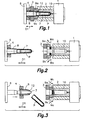
- a first embodiment of the apparatus of the invention which corresponds to its simplest expression and is adapted to produce preforms P comprising, according to the example shown, a test tube-shaped body with a neck and a mouth.
- the apparatus of this first embodiment comprises an injection hot runner 1, to which there is joined a cavity block 2 containing an injection cavity 10 connected to said hot runner 1.
- the mentioned injection cavity 10 defines a first part of a mold of the preform P corresponding to an outer surface of said test tube-shaped body.
- the mentioned hot runner 1 and the cavity block 2 form a fixed part 20 joined to a fixed tray of an injecting machine (not shown).
- This fixed part 20 of the apparatus has associated thereto a neck-bearing plate 3 on which injection neck splits 9a, 9b are assembled.
- the mentioned neck-bearing plate 3 is provided with a small movement to move closer to or away from the cavity block 2 and said injection neck splits 9a, 9b are provided with movements to move closer to or away from one another.
- the injection neck splits 9a, 9b are adapted to adopt a closed position next to the opening of said injection cavity 10 ( Figure 1) defining a second part of said mold of the preform P during the injection operation, and to later open ( Figure 2), carrying out a combined opening movement symbolized by arrows Ma, to allow the removal of the molded preform P.
- the mentioned second part of the mold of the preform P, defined by said injection neck splits 9a, 9b, corresponds to an outer surface of said neck, and usually includes a configuration for forming a screw thread and/or an annular rib in said outer surface of the neck of the preform P.
- the apparatus further comprises a moving part 30 fixed to a moving tray of said injecting machine.
- This moving part 30 is formed by a baseplate 6 to which there is joined to a core 7 configured to define a third part of the mold of the preform P corresponding to an inner surface of both the test tube-shaped body and the neck of the preform.
- the mentioned baseplate 6 is assembled in a moving, guided manner, and is actuated to move in a first direction D1 between a closed position, shown in Figure 1, in which said core 7 is introduced in the injection cavity 10, and an open position, shown in Figure 2, in which the core 7 is removed from said injection cavity 10.
- the apparatus is adapted to carry out an injection operation for injecting a molten plastic material (for example, polyethylene terephthalate (PET)) to mold the preform P inside the mold defined when the baseplate 6 is in the closed position and a subsequent cooling operation for cooling the preform P in the same injection cavity 10 before the baseplate 6 goes to its open position.
- a molten plastic material for example, polyethylene terephthalate (PET)
- PET polyethylene terephthalate
- the cavity block is generally provided with a circuit for a cooling fluid (not shown).
- the moving part 30 of the apparatus further comprises an ejecting element 8 associated to said core 7, which forms the characteristic element of the apparatus according to the present invention.
- the mentioned ejecting element 8 has the form of a sleeve arranged around the core 7 and comprises an end annular surface 12 that defines when the baseplate 6 is in the closed position ( Figure 1), a fourth part of the mold of the preform P substantially corresponding to an end annular part around said mouth of the preform P.
- the ejecting element 8 is connected to an ejecting plate 4 guided and actuated to move the ejecting element 8 along the core 7 in a back and forth movement which is carried out while the baseplate 6 is in said open position ( Figure 3) for the purpose of ejecting the preform P from the core 7.
- the cavity block 2 includes any operating number of injection cavities 10 and the baseplate 6 has an identical number of cores 7, the operation cycle being carried out jointly for all of them in a manner similar to that described above in relation to Figures 1 to 3 for a single injection cavity 10 and a single core 7.
- each core 7 has associated thereto its own ejecting element 8, and all the ejecting elements 8 are joined to a single common ejecting plate 4.
- the mold cavity is defined by only three basic elements
- the mold cavity, and therefore the geometry of the preform P is defined by four basic elements.
- these four basic elements are: the injection cavity 10, forming the outer part of the body of the preform P; the core 7, forming the inner part of the preform P; the injection neck splits 9a, 9b, forming the outer part of the neck of the preform P; and the ejecting element 8, forming the upper front part of the mouth of the preform P.
- the novelty is the ejecting element 8, which is used after the injection to eject the preform P from the core 7.
- the cooling operation is completed in a cooling cavity 11a, 11b different from the injection cavity 10 for the purpose of reducing the duration of the cycle for injecting-cooling-ejecting the preform P.
- the preforms P produced comprise a test tube-shaped body, with a neck and a mouth.
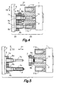
- the apparatus comprises a fixed part 20 joined to a fixed tray of an injecting machine (not shown) and a moving part 30 fixed to a moving tray of said machine ( Figure 4).
- the fixed part 20 is formed by a injection hot runner 1 to which there is joined a cavity block 2 containing at least one injection cavity 10 defining a first part of a mold cavity in which the preform P will be formed during the injection operation.
- the cavity block 2 has associated thereto a neck-bearing plate 3 supporting two injection neck splits 9a and 9b adapted to close next to the opening of the injection cavity 10 to form a second part of the preform, and to open.
- the injection cavity 10 is placed between two cooling cavities 11a and 11b adapted to cool the outside of the preform P by means of a circuit for a cooling fluid (not shown) in a cooling operation after the injection operation.
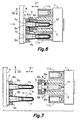
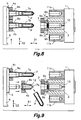
- the moving part 30 comprises a baseplate 6 guided and actuated to move in a first direction D1 between a closed position, shown in Figures 4, 6 and 10, and an open position, shown in Figures 5, 7, 8 and 9.
- a core-carrying plate 5 to which two cores 7a, 7b are fixed is assembled on the baseplate 6.
- the mentioned core-carrying plate 5 is adapted and actuated to be moved on the baseplate 6 in a second direction D2 transverse to the first direction D1.
- a control device controls in combination movements of the baseplate 6 in the first direction D1 and of the core-carrying plate 5 in the second direction D2 to alternately introduce the cores 7a, 7b in the injection cavity 10 and in one of the two cooling cavities 11a, 11b, as will be described in more detail below.
- Each core 7a, 7b has associated thereto a respective ejecting element 8a, 8b similar to the ejecting element 8 described above in relation to the first embodiment, and each ejecting element 8a, 8b is connected to a respective ejecting plate 4a, 4b independently actuated to carry out a back and forth movement of the ejecting element 8a, 8b along its respective core 7a, 7b whereas the baseplate 6 is in said open position for the purpose of ejecting the preform P.
- the mold cavity is formed by four basic elements, which in this case are: injection cavity 10; injection neck splits 9a and 9b; and, alternately, either core 7a, 7b and the ejecting element 8a, 8b associated thereto.
- the operation of the apparatus according to the second embodiment is as follows.
- the cycle starts, for example, with the apparatus in the position shown in Figure 5, where the baseplate 6 is in the open position and the core-carrying plate 5 is in one of two possible positions, called “lower position” herein in relation to the views shown in the figures.
- a first core 7a of the two cores 7a, 7b is bare and opposite to the injection cavity 10, next to which the two injection neck splits 9a, 9b are closed, whereas the second core 7b is opposite to one of the cooling cavities, called “lower cooling cavity 11b" herein in relation to the views shown in the figures.
- a preform P which is still not sufficiently cooled and comes from a previous injection operation is located on this second core 7b.
- the baseplate 6 is then moved to its closed position shown in Figure 6 without changing the position of the core-carrying plate 5, where the first core 7a is introduced in the injection cavity 10 such that the cavity of the mold of the preform P is completed by the joint cooperation of several surfaces of the injection cavity 10, of the injection neck splits 9a, 9b, of the first core 7a and of a first ejecting element 8a of the two ejecting elements 8a, 8b, which ejecting element is associated with the first core 7a.
- the molten plastic material coming from the injection hot runner 1 is injected inside the cavity of the mold to form a first preform P.
- the second core 7b, with the corresponding preform P arranged thereon has been introduced in said lower cooling cavity 11b where the cooling of the preform P is completed to a desired level.
- the baseplate 6 then starts a movement toward its open position while at the same time the neck-bearing plate 3 and the injection neck splits 9a, 9b carry out a synchronized combined opening movement symbolized by arrows Ma.
- the injection neck splits 9a, 9b aid in dragging the preform P together with the first core 7a, until being completely open to allow completely removing the first core 7a and demolding the preform P from the injection cavity 10.
- the second core 7b is simply removed from the lower cooling cavity 11b with the sufficiently cooled preform P thereon.
- the neck-bearing plate 3 and the injection neck splits 9a, 9b carry out a combined closing movement symbolized by arrows Mc, whereby the in jection neck splits 9a, 9b return to their initial closed position.
- the core-carrying plate 5 is moved by means of a hydraulic or motor-driven mechanism on the baseplate 6 towards the position shown in Figure 8, in which the first core 7a, having the recently injected and hot preform P, is opposite to the upper cooling cavity 11a while at the same time the second core 7b, having the cooled preform P, is opposite to the injection cavity 10.
- the second ejecting element 8b is then moved by its respective ejecting plate 4b in a back and forth movement along the second core 7b to eject the cooled preform P, whereby the second core 7b is now bare and opposite to the injection cavity 10.
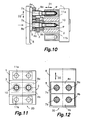
- the baseplate 6 is finally again moved to the closed position, as shown in Figure 10, whereby the first core 7a, having the recently injected and hot preform P, is introduced in the upper cooling cavity superior 11a, and the second bare core 7b is inserted in an injection chamber 10 such that the mold cavity of the preform P is completed by the joint cooperation of several surfaces of the injection cavity 10, of the injection neck splits 9a, 9b, of the second core 7b and of the second ejecting element 8b.
- the hot preform P is thus cooled in the upper cooling cavity 11a while a new preform P is injected on the second core 7b in the injection cavity 10.
- control device controls the movements of the ejecting plates 4a, 4b to only eject the preform P of that core 7a, 7b which has been removed from a cooling cavity 11a, 11b, but on the other hand does not act in the core 7a, 7b making the transition from the injection cavity 10 to one of the cooling cavities 11a, 11b.
- Figures 11 and 12 show schematic plan views of the fixed part 20 and the moving part 30 of an apparatus according to a variant of this second embodiment.
- the cavity block 2 includes a row with a number of injection cavities 10 which is arranged between two rows with an identical number of cooling cavities 11 a, 11b each.
- Figure 12 shows the baseplate 6 on which the core-carrying plate 5 is assembled, which core plate has a number of cores 7a, 7b that is twice the number of cavities of injection cavities 10.
- the cores 7a, 7b are divided into two rows arranged at a distance equal to the distance between the injection cavities 10 and the cooling cavities 11 a, 11b.
- each core 7a, 7b has its own ejecting element 8a, 8b associated thereto, and all the ejecting elements 8a associated to the cores 7a of one of the rows are joined to a first common ejecting plate 4a, and all the ejecting elements 8b associated to the cores 7b of the other row are joined to a second common ejecting plate 4b.
- the first and second ejecting plates 4a, 4b are independently actuated and controlled.
- the fixed part of the apparatus comprises a number of cavity blocks 2, each one including a row of injection cavities 10.
- the cavity blocks 2 are alternately placed among an identical number plus one of cooling blocks, each of which includes a row of cooling cavities 11a, 11b.
- a number n of rows of injection cavities 10 are alternately placed with a number n+1 of rows of cooling cavities 11a, 11b ( Figure 16), the two end rows being rows of cooling cavities.
- Figure 16 shows the injection cavities 10 and the cooling cavities 11a, 11 b formed in separate blocks, in a preferred embodiment, both the injection cavities 10 and the cooling cavities 11a, 11b are formed in a same block and are arranged in respective alternately placed rows in the manner described in relation to Figure 16.
- the moving part comprises the baseplate 6 on which the core-carrying plate 5 is assembled, which core plate has a number 2n of rows of cores 7a, 7b, i.e., a number of rows of cores 7a, 7b that is twice the number of rows of injection cavities 10.
- the core-carrying plate 5 is adapted and actuated to be moved on the baseplate 6 in a second direction D2 transverse to the first direction D1 to alternately oppose the rows of cores 7a, 7b to the rows of injection cavities 10 and to the rows of cooling cavities 1 1a, 11b.
- All the ejecting elements 8a, 8b associated to the cores 7a, 7b of each of the rows are joined to a common independently actuated and controlled ejecting plate 4a, 4b.
- a common independently actuated and controlled ejecting plate 4a, 4b there is an independent ejecting plate 4a, 4b for each row of cores 7a, 7b.
- the movements of the baseplate 6 in the first direction D1 are actuated in combination with the movements of the core-carrying plate 5 in the second direction D2 to alternately and cyclically introduce the rows of cores 7a, 7b in the rows of injection cavities 10 and in the rows of cooling cavities 11a, 11 b.
- An actuation plate 50 is associated to the baseplate 6 and is actuated to be moved in the first direction D1 in relation thereto.
- An actuation plate 50 is associated to the baseplate 6 and is actuated to be moved in the first direction D1 in relation thereto.
- the ejecting plates 4a, 4b associated to those cores 7a, 7b which have been removed from the cooling cavities 11a, 11b are selectively dragged by a movement of said actuation plate 50, whereas the ejecting plates 4a, 4b associated to those cores 7a, 7b which have been removed from the injection cavities 10 are retained next to the core-carrying plate 5.
- the actuation plate 50 is provided with first selecting elements 51 cooperating with second selecting elements 52 assembled in the baseplate 6 to mechanically select which ejecting plates 4a, 4b will be dragged by the actuation plate 50 and which will be retained next to the core-carrying plate 5 according to the position of the ejecting plates 4a, 4b in relation to the baseplate 6 in the second direction D2.
- the first selecting elements 51 are adapted to be coupled to the ejecting plates 4a, 4b which must be dragged, thus linking them to the actuation plate 50
- the second selecting elements 52 are adapted to retain the ejecting plates 4a, 4b which must not be moved next to the core-carrying plate 5 when the core-carrying plate 5 is cyclically moved in direction D2 to alternately change the rows of cores 7a, 7b from their positions opposite to the rows of injection cavities 10 and to the rows of cooling cavities 11a, 11b.
- the movements of the core-carrying plate 5 in the second direction D2 alternately couple and uncouple the ejecting plates 4a, 4b with the first and second ejecting elements 51, 52.
- FIGs 15A and 15B show the first selecting elements 51 in greater detail.
- the actuation plate 50 defines a frame inside which the ejecting plates 4a, 4b move in the second direction D2.
- the first selecting elements 51 comprise pairs of parallel flaps 53 formed in the actuation plate 50 and extending towards the inside of the mentioned frame from opposite edges thereof (see also Figure 13).
- a groove 54 is defined between each pair of flaps 53, which groove is adapted to receive a flange 55 formed in the corresponding edge of each ejecting plate 4a, 4b.
- each of the mentioned flanges 55 has a cavity 59 adapted to receive the insertion of a finger 56 that is elastically loaded by a spring 57 for example.
- the mentioned finger 56 is assembled in a cavity of the actuation plate 50 such that it can be moved in relation to the actuation plate 50 in direction D1.
- the finger 56 is joined to an appendage 60 passed through an opening of the actuation plate 50 such that said appendage is pressed by the baseplate 6 when the actuation plate 50 is in its retracted position ( Figure 15A).
- the finger 56 is thus pushed against the force of the spring 57 out of its coupling with the cavity 59 of the flange 55 and the ejecting plate 4a, 4b is free to move in direction D2.
- the spring 57 pushes the finger 57 inside the cavity 59 and the appendage 60 projects from the actuation plate 50.
- the fingers 56 have the function of retaining the flanges 55 in the correct position in relation to the grooves 54 of the actuation plate 50, which is especially necessary when the baseplate 6 is installed in a vertical arrangement.
- Figure 14 shows the second selecting elements 52 in greater detail, which selecting elements comprise retaining fingers 58 joined to the baseplate 6 and housed in holes of the actuation plate 50, such that said retaining fingers 58 project towards the inside of the frame defined by the actuation plate 50 so as to be placed above the flanges 55 of the ejecting plates 4a, 4b when the ejecting plates 4a, 4b are moved in the second direction D2.
- selecting elements comprise retaining fingers 58 joined to the baseplate 6 and housed in holes of the actuation plate 50, such that said retaining fingers 58 project towards the inside of the frame defined by the actuation plate 50 so as to be placed above the flanges 55 of the ejecting plates 4a, 4b when the ejecting plates 4a, 4b are moved in the second direction D2.
- the first selecting elements 51 are alternated with the second selecting elements 52, the selecting elements located at both ends of the baseplate 6 being second selecting elements 52.
- Figures 13 to 16 show some of the ejecting plates 4a retained by the second selecting elements 52 and other alternated ejecting plates 4b coupled to the first selecting elements 51.
- the core-carrying plate 5 will be moved in the second direction D2, whereby the ejecting plates 4a previously retained by the second selecting elements 52 will be coupled to the first selecting elements 51 and the ejecting plates 4b previously coupled to the first selecting elements 51 will be retained by the second selecting elements 52, and so on.
- Figures 17 and 18 show schematic plan views of the fixed part 20 and the moving part 30 of an apparatus according to a third embodiment.
- the cavity block 2 shown in Figure 17 includes a group of injection cavities 10 arranged according to a matrix of, for example, a number o rows by a number of columns.
- This group of injection cavities 10 is arranged between two groups of cooling cavities 11a, 11b, each of which is formed by an identical number of rows and an identical number of columns as the group of injection cavities 10.
- the example shown in Figure 17 shows matrices of two rows by two columns of elements, said matrices could obviously have any operating number of rows and columns.
- Figure 18 shows the baseplate 6 on which the core-carrying plate 5 is assembled, which core plate has a number of cores 7a, 7b that is twice the number of cavities of injection cavities 10.
- the cores 7a, 7b are divided into two groups, each group having an identical number of rows and an identical number of columns as the group of injection cavities 10, both groups being separated by a distance equal to the distance between the groups of the injection cavities 10 and the groups of cooling cavities 11 a, 11b.
- each core 7a, 7b has its own ejecting element 8a, 8b associated thereto, and all the ejecting elements 8a associated to the cores 7a of one of the groups are joined to a first common ejecting plate 4a, and all the ejecting elements 8b associated to the cores 7b of the other group are joined to a second common ejecting plate 4b.
- the first and second ejecting plates 4a, 4b are independently actuated and controlled.
- the fixed part of the apparatus comprises a number of groups of injection cavities alternated with groups of cooling cavities, the two end groups being groups of cooling cavities.
- the moving part comprises a number of groups of cores that is twice the number of groups of injection cavities. All the ejecting elements associated to the cores of each of the groups of cores are joined to a common independently actuated and controlled ejecting plate.
Landscapes
- Engineering & Computer Science (AREA)
- Manufacturing & Machinery (AREA)
- Mechanical Engineering (AREA)
- Processing And Handling Of Plastics And Other Materials For Molding In General (AREA)
- Blow-Moulding Or Thermoforming Of Plastics Or The Like (AREA)
- Moulds For Moulding Plastics Or The Like (AREA)
Priority Applications (3)
| Application Number | Priority Date | Filing Date | Title |
|---|---|---|---|
| EP05380003A EP1676689A1 (fr) | 2005-01-04 | 2005-01-04 | Dispositif de moulage par injection de préformes |
| EP06708820A EP1834751A4 (fr) | 2005-01-04 | 2006-01-02 | Appareil de moulage d'injection de preformes |
| PCT/ES2006/000001 WO2006072646A1 (fr) | 2005-01-04 | 2006-01-02 | Appareil de moulage d'injection de preformes |
Applications Claiming Priority (3)
| Application Number | Priority Date | Filing Date | Title |
|---|---|---|---|
| EP05380003A EP1676689A1 (fr) | 2005-01-04 | 2005-01-04 | Dispositif de moulage par injection de préformes |
| EP06708820A EP1834751A4 (fr) | 2005-01-04 | 2006-01-02 | Appareil de moulage d'injection de preformes |
| PCT/ES2006/000001 WO2006072646A1 (fr) | 2005-01-04 | 2006-01-02 | Appareil de moulage d'injection de preformes |
Publications (2)
| Publication Number | Publication Date |
|---|---|
| EP1834751A1 true EP1834751A1 (fr) | 2007-09-19 |
| EP1834751A4 EP1834751A4 (fr) | 2011-04-27 |
Family
ID=38353218
Family Applications (2)
| Application Number | Title | Priority Date | Filing Date |
|---|---|---|---|
| EP05380003A Withdrawn EP1676689A1 (fr) | 2005-01-04 | 2005-01-04 | Dispositif de moulage par injection de préformes |
| EP06708820A Withdrawn EP1834751A4 (fr) | 2005-01-04 | 2006-01-02 | Appareil de moulage d'injection de preformes |
Family Applications Before (1)
| Application Number | Title | Priority Date | Filing Date |
|---|---|---|---|
| EP05380003A Withdrawn EP1676689A1 (fr) | 2005-01-04 | 2005-01-04 | Dispositif de moulage par injection de préformes |
Country Status (2)
| Country | Link |
|---|---|
| EP (2) | EP1676689A1 (fr) |
| WO (1) | WO2006072646A1 (fr) |
Cited By (2)
| Publication number | Priority date | Publication date | Assignee | Title |
|---|---|---|---|---|
| CN103624930A (zh) * | 2012-08-29 | 2014-03-12 | 王振有 | 多工位注塑机热熔腔自加热模具 |
| US8678810B2 (en) | 2006-02-03 | 2014-03-25 | Industrial De Moldes Y Matrices, S.A. | Apparatus and method for the production of bi-material hollow bodies by means of injection overmolding |
Families Citing this family (6)
| Publication number | Priority date | Publication date | Assignee | Title |
|---|---|---|---|---|
| CA2641369C (fr) * | 2006-02-03 | 2012-05-01 | Industrial De Moldes Y Matrices, S.A. | Appareil et procede destines a fabriquer des corps creux constitues de deux materiaux par surmoulage par injection |
| ES1074236Y (es) | 2011-02-22 | 2011-07-01 | Molmasa Aplicaciones Tecn S L | Dispositivo de traslacion de piezas moldeadas aplicable a moldes de inyeccion de plastico. |
| WO2016070287A1 (fr) | 2014-11-07 | 2016-05-12 | Mold-Masters (2007) Limited | Système de moulage de préforme et empilement de moules destiné à un système de moulage de préforme |
| JP6717511B1 (ja) * | 2019-06-11 | 2020-07-01 | 株式会社青木固研究所 | ホットランナー装置における溶融樹脂の分岐方法、及び射出延伸ブロー成形機 |
| CN114939961B (zh) * | 2022-06-24 | 2025-08-01 | 广东星联精密机械有限公司 | 一种模腔板组件、模腔组件及注坯模具 |
| CN116039007A (zh) * | 2023-01-19 | 2023-05-02 | 浙江宏振机械模具集团有限公司 | 一种散热效果好的多层瓶坯用注塑装置 |
Family Cites Families (9)
| Publication number | Priority date | Publication date | Assignee | Title |
|---|---|---|---|---|
| US4285657A (en) * | 1979-12-03 | 1981-08-25 | Ryder Leonard B | Injection blow molding apparatus |
| JPH0735088B2 (ja) * | 1990-09-29 | 1995-04-19 | 日精エー・エス・ビー機械株式会社内 | パリソン射出成形装置 |
| US5662856A (en) * | 1995-07-12 | 1997-09-02 | Imesco, Inc. | Low-pressure method for the preparation of hollow plastic articles |
| US5736173A (en) * | 1996-04-24 | 1998-04-07 | Zygo Mold Limited | Preform injection mould with slide taper locks |
| NL1005872C2 (nl) * | 1997-04-22 | 1998-10-29 | Inter Tooling Services Bv | Spuitgietmachine voor het spuitgieten van preforms voor kunststof flessen en soortgelijke houders. |
| US6398537B2 (en) * | 1999-04-02 | 2002-06-04 | Mold-Masters Limited | Shuttle system for an apparatus for injection molding |
| CA2505697C (fr) * | 2002-11-08 | 2013-10-22 | Advanced Plastics Technologies Ltd. | Moule d'injection ayant une portion resistante a l'usure et une portion de transfert de chaleur elevee et une methode de formation d'une preforme |
| JP4115254B2 (ja) * | 2002-11-15 | 2008-07-09 | 北海製罐株式会社 | 射出成形機におけるプリフォームの取出移送装置 |
| TW200508004A (en) * | 2003-07-18 | 2005-03-01 | Sumitomo Heavy Industries | Molding method, mold for molding, molded product, and molding machine |
-
2005
- 2005-01-04 EP EP05380003A patent/EP1676689A1/fr not_active Withdrawn
-
2006
- 2006-01-02 WO PCT/ES2006/000001 patent/WO2006072646A1/fr not_active Ceased
- 2006-01-02 EP EP06708820A patent/EP1834751A4/fr not_active Withdrawn
Cited By (2)
| Publication number | Priority date | Publication date | Assignee | Title |
|---|---|---|---|---|
| US8678810B2 (en) | 2006-02-03 | 2014-03-25 | Industrial De Moldes Y Matrices, S.A. | Apparatus and method for the production of bi-material hollow bodies by means of injection overmolding |
| CN103624930A (zh) * | 2012-08-29 | 2014-03-12 | 王振有 | 多工位注塑机热熔腔自加热模具 |
Also Published As
| Publication number | Publication date |
|---|---|
| EP1676689A1 (fr) | 2006-07-05 |
| WO2006072646A1 (fr) | 2006-07-13 |
| EP1834751A4 (fr) | 2011-04-27 |
Similar Documents
| Publication | Publication Date | Title |
|---|---|---|
| US8459977B2 (en) | Molded article transfer device | |
| CN102470593A (zh) | 具有往返运动的成模物件转移设备 | |
| JPS60264222A (ja) | 射出吹出成形方法及びその装置 | |
| CN102773970B (zh) | 离合器式滑块机构 | |
| JPH04138214A (ja) | パリソン射出成形装置 | |
| CN205588574U (zh) | 一种前后模均不同的双色塑胶制品的注塑模具 | |
| US10647029B2 (en) | Separating device for a mold comprising a chain of articulated links | |
| JP2017030358A (ja) | 射出金型装置 | |
| ITTO950709A1 (it) | Un apparecchio e un metodo per lo stampaggio a iniezione e soffiatura | |
| US20130071512A1 (en) | Opening device of slides in moulds for the ejection of moulded parts | |
| KR101678958B1 (ko) | 사출금형의 보스부위 싱크마크 생성방지 장치 | |
| CN202062596U (zh) | 离合器式滑块机构 | |
| CA2641369A1 (fr) | Appareil et procede destines a fabriquer des corps creux constitues de deux materiaux par surmoulage par injection | |
| CN107116762B (zh) | 用于注塑板件的模具及其注塑方法 | |
| KR101206574B1 (ko) | 성형 제품의 성형후 처리를 위한 방법 및 이 방법을 실시하기 위한 장치 | |
| KR100625868B1 (ko) | 사출성형용 금형장치 | |
| EP2877334B1 (fr) | Procédé et contrôleur pour le transfert d'un objet moulé | |
| KR102221394B1 (ko) | 사출 금형 장치의 언더컷 성형 어셈블리 및 이를 이용한 사출 성형물 제조 방법 | |
| JP2007144755A (ja) | 射出成形金型のスライドコア開閉構造 | |
| US20070059395A1 (en) | Molded article handling device | |
| WO2006072646A1 (fr) | Appareil de moulage d'injection de preformes | |
| US20250222637A1 (en) | Injection molding device with rotatable core sections | |
| US20030146546A1 (en) | Injection mold for plastic caps, with carriage | |
| CN210190462U (zh) | 一种具有气动顶出以及推环的注塑模具 | |
| CN107685417B (zh) | 用于生产多个不同注塑成型品的注塑成型机 |
Legal Events
| Date | Code | Title | Description |
|---|---|---|---|
| PUAI | Public reference made under article 153(3) epc to a published international application that has entered the european phase |
Free format text: ORIGINAL CODE: 0009012 |
|
| 17P | Request for examination filed |
Effective date: 20070625 |
|
| AK | Designated contracting states |
Kind code of ref document: A1 Designated state(s): AT BE BG CH CY CZ DE DK EE ES FI FR GB GR HU IE IS IT LI LT LU LV MC NL PL PT RO SE SI SK TR |
|
| DAX | Request for extension of the european patent (deleted) | ||
| RAP1 | Party data changed (applicant data changed or rights of an application transferred) |
Owner name: MOLMASA APLICACIONES TECNICAS, S.L. |
|
| A4 | Supplementary search report drawn up and despatched |
Effective date: 20110324 |
|
| RIC1 | Information provided on ipc code assigned before grant |
Ipc: B29C 45/72 20060101AFI20110318BHEP Ipc: B29C 45/40 20060101ALI20110318BHEP |
|
| 17Q | First examination report despatched |
Effective date: 20120221 |
|
| GRAP | Despatch of communication of intention to grant a patent |
Free format text: ORIGINAL CODE: EPIDOSNIGR1 |
|
| RIN1 | Information on inventor provided before grant (corrected) |
Inventor name: ATANCE ORDEN, ANGEL |
|
| STAA | Information on the status of an ep patent application or granted ep patent |
Free format text: STATUS: THE APPLICATION IS DEEMED TO BE WITHDRAWN |
|
| 18D | Application deemed to be withdrawn |
Effective date: 20121128 |