EP1835140B1 - Abgasreinigungssystem und dazugehöriges Diagnoseverfahren - Google Patents
Abgasreinigungssystem und dazugehöriges Diagnoseverfahren Download PDFInfo
- Publication number
- EP1835140B1 EP1835140B1 EP07104230.3A EP07104230A EP1835140B1 EP 1835140 B1 EP1835140 B1 EP 1835140B1 EP 07104230 A EP07104230 A EP 07104230A EP 1835140 B1 EP1835140 B1 EP 1835140B1
- Authority
- EP
- European Patent Office
- Prior art keywords
- air
- fuel ratio
- exhaust gas
- bypass
- gas passage
- Prior art date
- Legal status (The legal status is an assumption and is not a legal conclusion. Google has not performed a legal analysis and makes no representation as to the accuracy of the status listed.)
- Not-in-force
Links
Images



Classifications
-
- F—MECHANICAL ENGINEERING; LIGHTING; HEATING; WEAPONS; BLASTING
- F01—MACHINES OR ENGINES IN GENERAL; ENGINE PLANTS IN GENERAL; STEAM ENGINES
- F01N—GAS-FLOW SILENCERS OR EXHAUST APPARATUS FOR MACHINES OR ENGINES IN GENERAL; GAS-FLOW SILENCERS OR EXHAUST APPARATUS FOR INTERNAL-COMBUSTION ENGINES
- F01N3/00—Exhaust or silencing apparatus having means for purifying, rendering innocuous, or otherwise treating exhaust
- F01N3/08—Exhaust or silencing apparatus having means for purifying, rendering innocuous, or otherwise treating exhaust for rendering innocuous
- F01N3/10—Exhaust or silencing apparatus having means for purifying, rendering innocuous, or otherwise treating exhaust for rendering innocuous by thermal or catalytic conversion of noxious components of exhaust
- F01N3/18—Exhaust or silencing apparatus having means for purifying, rendering innocuous, or otherwise treating exhaust for rendering innocuous by thermal or catalytic conversion of noxious components of exhaust characterised by methods of operation; Control
- F01N3/20—Exhaust or silencing apparatus having means for purifying, rendering innocuous, or otherwise treating exhaust for rendering innocuous by thermal or catalytic conversion of noxious components of exhaust characterised by methods of operation; Control specially adapted for catalytic conversion
- F01N3/2053—By-passing catalytic reactors, e.g. to prevent overheating
-
- F—MECHANICAL ENGINEERING; LIGHTING; HEATING; WEAPONS; BLASTING
- F01—MACHINES OR ENGINES IN GENERAL; ENGINE PLANTS IN GENERAL; STEAM ENGINES
- F01N—GAS-FLOW SILENCERS OR EXHAUST APPARATUS FOR MACHINES OR ENGINES IN GENERAL; GAS-FLOW SILENCERS OR EXHAUST APPARATUS FOR INTERNAL-COMBUSTION ENGINES
- F01N3/00—Exhaust or silencing apparatus having means for purifying, rendering innocuous, or otherwise treating exhaust
- F01N3/08—Exhaust or silencing apparatus having means for purifying, rendering innocuous, or otherwise treating exhaust for rendering innocuous
- F01N3/10—Exhaust or silencing apparatus having means for purifying, rendering innocuous, or otherwise treating exhaust for rendering innocuous by thermal or catalytic conversion of noxious components of exhaust
- F01N3/18—Exhaust or silencing apparatus having means for purifying, rendering innocuous, or otherwise treating exhaust for rendering innocuous by thermal or catalytic conversion of noxious components of exhaust characterised by methods of operation; Control
- F01N3/20—Exhaust or silencing apparatus having means for purifying, rendering innocuous, or otherwise treating exhaust for rendering innocuous by thermal or catalytic conversion of noxious components of exhaust characterised by methods of operation; Control specially adapted for catalytic conversion
-
- F—MECHANICAL ENGINEERING; LIGHTING; HEATING; WEAPONS; BLASTING
- F01—MACHINES OR ENGINES IN GENERAL; ENGINE PLANTS IN GENERAL; STEAM ENGINES
- F01N—GAS-FLOW SILENCERS OR EXHAUST APPARATUS FOR MACHINES OR ENGINES IN GENERAL; GAS-FLOW SILENCERS OR EXHAUST APPARATUS FOR INTERNAL-COMBUSTION ENGINES
- F01N11/00—Monitoring or diagnostic devices for exhaust-gas treatment apparatus
- F01N11/007—Monitoring or diagnostic devices for exhaust-gas treatment apparatus the diagnostic devices measuring oxygen or air concentration downstream of the exhaust apparatus
-
- F—MECHANICAL ENGINEERING; LIGHTING; HEATING; WEAPONS; BLASTING
- F01—MACHINES OR ENGINES IN GENERAL; ENGINE PLANTS IN GENERAL; STEAM ENGINES
- F01N—GAS-FLOW SILENCERS OR EXHAUST APPARATUS FOR MACHINES OR ENGINES IN GENERAL; GAS-FLOW SILENCERS OR EXHAUST APPARATUS FOR INTERNAL-COMBUSTION ENGINES
- F01N13/00—Exhaust or silencing apparatus characterised by constructional features
- F01N13/009—Exhaust or silencing apparatus characterised by constructional features having two or more separate purifying devices arranged in series
-
- F—MECHANICAL ENGINEERING; LIGHTING; HEATING; WEAPONS; BLASTING
- F01—MACHINES OR ENGINES IN GENERAL; ENGINE PLANTS IN GENERAL; STEAM ENGINES
- F01N—GAS-FLOW SILENCERS OR EXHAUST APPARATUS FOR MACHINES OR ENGINES IN GENERAL; GAS-FLOW SILENCERS OR EXHAUST APPARATUS FOR INTERNAL-COMBUSTION ENGINES
- F01N13/00—Exhaust or silencing apparatus characterised by constructional features
- F01N13/009—Exhaust or silencing apparatus characterised by constructional features having two or more separate purifying devices arranged in series
- F01N13/0093—Exhaust or silencing apparatus characterised by constructional features having two or more separate purifying devices arranged in series the purifying devices are of the same type
-
- F—MECHANICAL ENGINEERING; LIGHTING; HEATING; WEAPONS; BLASTING
- F01—MACHINES OR ENGINES IN GENERAL; ENGINE PLANTS IN GENERAL; STEAM ENGINES
- F01N—GAS-FLOW SILENCERS OR EXHAUST APPARATUS FOR MACHINES OR ENGINES IN GENERAL; GAS-FLOW SILENCERS OR EXHAUST APPARATUS FOR INTERNAL-COMBUSTION ENGINES
- F01N3/00—Exhaust or silencing apparatus having means for purifying, rendering innocuous, or otherwise treating exhaust
- F01N3/02—Exhaust or silencing apparatus having means for purifying, rendering innocuous, or otherwise treating exhaust for cooling, or for removing solid constituents of, exhaust
- F01N3/021—Exhaust or silencing apparatus having means for purifying, rendering innocuous, or otherwise treating exhaust for cooling, or for removing solid constituents of, exhaust by means of filters
-
- F—MECHANICAL ENGINEERING; LIGHTING; HEATING; WEAPONS; BLASTING
- F01—MACHINES OR ENGINES IN GENERAL; ENGINE PLANTS IN GENERAL; STEAM ENGINES
- F01N—GAS-FLOW SILENCERS OR EXHAUST APPARATUS FOR MACHINES OR ENGINES IN GENERAL; GAS-FLOW SILENCERS OR EXHAUST APPARATUS FOR INTERNAL-COMBUSTION ENGINES
- F01N3/00—Exhaust or silencing apparatus having means for purifying, rendering innocuous, or otherwise treating exhaust
- F01N3/08—Exhaust or silencing apparatus having means for purifying, rendering innocuous, or otherwise treating exhaust for rendering innocuous
-
- F—MECHANICAL ENGINEERING; LIGHTING; HEATING; WEAPONS; BLASTING
- F01—MACHINES OR ENGINES IN GENERAL; ENGINE PLANTS IN GENERAL; STEAM ENGINES
- F01N—GAS-FLOW SILENCERS OR EXHAUST APPARATUS FOR MACHINES OR ENGINES IN GENERAL; GAS-FLOW SILENCERS OR EXHAUST APPARATUS FOR INTERNAL-COMBUSTION ENGINES
- F01N3/00—Exhaust or silencing apparatus having means for purifying, rendering innocuous, or otherwise treating exhaust
- F01N3/08—Exhaust or silencing apparatus having means for purifying, rendering innocuous, or otherwise treating exhaust for rendering innocuous
- F01N3/10—Exhaust or silencing apparatus having means for purifying, rendering innocuous, or otherwise treating exhaust for rendering innocuous by thermal or catalytic conversion of noxious components of exhaust
- F01N3/101—Three-way catalysts
-
- F—MECHANICAL ENGINEERING; LIGHTING; HEATING; WEAPONS; BLASTING
- F01—MACHINES OR ENGINES IN GENERAL; ENGINE PLANTS IN GENERAL; STEAM ENGINES
- F01N—GAS-FLOW SILENCERS OR EXHAUST APPARATUS FOR MACHINES OR ENGINES IN GENERAL; GAS-FLOW SILENCERS OR EXHAUST APPARATUS FOR INTERNAL-COMBUSTION ENGINES
- F01N9/00—Electrical control of exhaust gas treating apparatus
-
- F—MECHANICAL ENGINEERING; LIGHTING; HEATING; WEAPONS; BLASTING
- F01—MACHINES OR ENGINES IN GENERAL; ENGINE PLANTS IN GENERAL; STEAM ENGINES
- F01N—GAS-FLOW SILENCERS OR EXHAUST APPARATUS FOR MACHINES OR ENGINES IN GENERAL; GAS-FLOW SILENCERS OR EXHAUST APPARATUS FOR INTERNAL-COMBUSTION ENGINES
- F01N2550/00—Monitoring or diagnosing the deterioration of exhaust systems
- F01N2550/06—By-pass systems
- F01N2550/10—By-pass systems of catalytic converters
-
- F—MECHANICAL ENGINEERING; LIGHTING; HEATING; WEAPONS; BLASTING
- F01—MACHINES OR ENGINES IN GENERAL; ENGINE PLANTS IN GENERAL; STEAM ENGINES
- F01N—GAS-FLOW SILENCERS OR EXHAUST APPARATUS FOR MACHINES OR ENGINES IN GENERAL; GAS-FLOW SILENCERS OR EXHAUST APPARATUS FOR INTERNAL-COMBUSTION ENGINES
- F01N2560/00—Exhaust systems with means for detecting or measuring exhaust gas components or characteristics
- F01N2560/02—Exhaust systems with means for detecting or measuring exhaust gas components or characteristics the means being an exhaust gas sensor
- F01N2560/025—Exhaust systems with means for detecting or measuring exhaust gas components or characteristics the means being an exhaust gas sensor for measuring or detecting O2, e.g. lambda sensors
-
- F—MECHANICAL ENGINEERING; LIGHTING; HEATING; WEAPONS; BLASTING
- F01—MACHINES OR ENGINES IN GENERAL; ENGINE PLANTS IN GENERAL; STEAM ENGINES
- F01N—GAS-FLOW SILENCERS OR EXHAUST APPARATUS FOR MACHINES OR ENGINES IN GENERAL; GAS-FLOW SILENCERS OR EXHAUST APPARATUS FOR INTERNAL-COMBUSTION ENGINES
- F01N2560/00—Exhaust systems with means for detecting or measuring exhaust gas components or characteristics
- F01N2560/14—Exhaust systems with means for detecting or measuring exhaust gas components or characteristics having more than one sensor of one kind
-
- F—MECHANICAL ENGINEERING; LIGHTING; HEATING; WEAPONS; BLASTING
- F02—COMBUSTION ENGINES; HOT-GAS OR COMBUSTION-PRODUCT ENGINE PLANTS
- F02D—CONTROLLING COMBUSTION ENGINES
- F02D41/00—Electrical control of supply of combustible mixture or its constituents
- F02D41/02—Circuit arrangements for generating control signals
- F02D41/14—Introducing closed-loop corrections
- F02D41/1438—Introducing closed-loop corrections using means for determining characteristics of the combustion gases; Sensors therefor
- F02D41/1493—Details
- F02D41/1495—Detection of abnormalities in the air/fuel ratio feedback system
-
- Y—GENERAL TAGGING OF NEW TECHNOLOGICAL DEVELOPMENTS; GENERAL TAGGING OF CROSS-SECTIONAL TECHNOLOGIES SPANNING OVER SEVERAL SECTIONS OF THE IPC; TECHNICAL SUBJECTS COVERED BY FORMER USPC CROSS-REFERENCE ART COLLECTIONS [XRACs] AND DIGESTS
- Y02—TECHNOLOGIES OR APPLICATIONS FOR MITIGATION OR ADAPTATION AGAINST CLIMATE CHANGE
- Y02A—TECHNOLOGIES FOR ADAPTATION TO CLIMATE CHANGE
- Y02A50/00—TECHNOLOGIES FOR ADAPTATION TO CLIMATE CHANGE in human health protection, e.g. against extreme weather
- Y02A50/20—Air quality improvement or preservation, e.g. vehicle emission control or emission reduction by using catalytic converters
-
- Y—GENERAL TAGGING OF NEW TECHNOLOGICAL DEVELOPMENTS; GENERAL TAGGING OF CROSS-SECTIONAL TECHNOLOGIES SPANNING OVER SEVERAL SECTIONS OF THE IPC; TECHNICAL SUBJECTS COVERED BY FORMER USPC CROSS-REFERENCE ART COLLECTIONS [XRACs] AND DIGESTS
- Y02—TECHNOLOGIES OR APPLICATIONS FOR MITIGATION OR ADAPTATION AGAINST CLIMATE CHANGE
- Y02T—CLIMATE CHANGE MITIGATION TECHNOLOGIES RELATED TO TRANSPORTATION
- Y02T10/00—Road transport of goods or passengers
- Y02T10/10—Internal combustion engine [ICE] based vehicles
- Y02T10/12—Improving ICE efficiencies
-
- Y—GENERAL TAGGING OF NEW TECHNOLOGICAL DEVELOPMENTS; GENERAL TAGGING OF CROSS-SECTIONAL TECHNOLOGIES SPANNING OVER SEVERAL SECTIONS OF THE IPC; TECHNICAL SUBJECTS COVERED BY FORMER USPC CROSS-REFERENCE ART COLLECTIONS [XRACs] AND DIGESTS
- Y02—TECHNOLOGIES OR APPLICATIONS FOR MITIGATION OR ADAPTATION AGAINST CLIMATE CHANGE
- Y02T—CLIMATE CHANGE MITIGATION TECHNOLOGIES RELATED TO TRANSPORTATION
- Y02T10/00—Road transport of goods or passengers
- Y02T10/10—Internal combustion engine [ICE] based vehicles
- Y02T10/40—Engine management systems
Definitions
- the present invention relates generally to exhaust gas purification and particularly, but not exclusively, to an apparatus and method for diagnosing whether there is any leakage by a flow path switching valve in an exhaust gas purifying system for example as known from JP 09 209 744A .
- purify refers to reducing the toxicity of the exhaust gases emitted by an internal combustion engine.
- Exhaust gas is introduced into a bypass exhaust gas passage that includes a bypass catalytic converter.
- the bypass exhaust gas passage is disposed relatively upstream of a main catalytic converter in a conventional exhaust system, and a flow path switching valve diverts the exhaust gas through the bypass exhaust gas passage after initiating a cold start-up of the engine.
- exhaust gas cannot be sufficiently purified between the cold start-up of an internal combustion engine and the full activation of a catalytic converter, i.e., when the catalytic converter's temperature increases sufficiently. This is especially the case when a main catalytic converter is disposed a distance downstream from the engine (e.g., underneath an automobile). However, if the main catalytic converter is disposed closer to the engine, then the durability or lifespan of the catalyst can be significantly compromised due to thermal deterioration.
- a related exhaust system includes a bypass exhaust gas passage and a bypass catalytic converter, which are disposed in parallel to an upstream portion of a main exhaust gas passage leading to a main catalytic converter.
- a flow path switching valve is configured to introduce the exhaust gas into the bypass exhaust gas passage immediately after initiating the cold start-up of the engine.
- unpurified exhaust gas may be discharged to the atmosphere until the main catalytic converter is fully activated.
- the related exhaust system includes a method for detecting flow rate reduction as a result of using the flow path switching valve; however, the related exhaust system fails to include anything in relation to diagnosing leakage of unpurified exhaust gas. Thus, there is a need for an apparatus that can properly diagnose leakage by the flow path switching valve.
- an apparatus for diagnosing an exhaust gas purification system for an internal combustion engine comprising a main exhaust gas passage, a main catalytic converter disposed in the main exhaust gas passage, a bypass exhaust gas passage in fluid communication with the main exhaust gas passage so as to bypass a section thereof between a branch point at which the bypass exhaust gas passage branches out of the main exhaust gas passage and a junction at which the bypass exhaust gas passage merges into the main exhaust gas passage at a upstream side of the main catalytic converter, a bypass catalytic converter disposed in the bypass exhaust gas passage, a valve provided in the section of the main exhaust gas passage and configured to open or close the section of the main exhaust gas passage, a first sensor disposed in the bypass exhaust gas passage to output a first signal indicative of a first air-fuel ratio of an exhaust gas flowing in the bypass exhaust gas passage, wherein the first sensor detects the first air-fuel ratio of exhaust gas upstream of the bypass catalytic converter, a second sensor disposed in the main exhaust gas passage to output a
- the second sensor may detect the second air-fuel ratio of exhaust gas downstream of the valve.
- the first signal indicates changes between rich and lean states of the first air-fuel ratio of exhaust gas passing through the bypass exhaust gas passage
- the second signal indicates changes between rich and lean states of the second air-fuel ratio of exhaust gas passing through the main exhaust gas passage.
- the determining whether the valve in the closed configuration is leaking comprises a time delay between the first signal indicating the changes between rich and lean states of the first air-fuel ratio and the second signal indicating the changes between rich and lean states of the second air-fuel ratio, the time delay being in response to periodic changes of an engine air-fuel ratio supplied to the internal combustion engine.
- the determining whether the valve in the closed configuration is leaking comprises determining that a leak exists when the time delay is not greater than a threshold value and determining that a leak does not exist when the time delay is greater than the threshold value.
- the determining whether the valve in the closed configuration is leaking comprises determining that a leak exists when the time delay is less than a first threshold value, determining that a leak does not exist when the time delay is greater than a second threshold value and determining that the bypass catalytic converter is deteriorated when the time delay is in a predetermined range between the first and second threshold values.
- the determining whether the valve in the closed configuration is leaking comprises comparing a first interval during which the first signal stays in one of the rich and lean states of the first air-fuel ratio to a second interval during which the second signal stays in one of the rich and lean states of the second air-fuel ratio, the changes between the rich and lean states of the first and second air-fuel ratios being in response to periodic changes of an engine air-fuel ratio supplied to the internal combustion engine.
- the determining whether the valve in the closed configuration is leaking comprises determining that a leak exists when the first interval is substantially equal to the second interval and determining that a leak does not exist when the first interval is less than the second interval.
- the determining whether the valve in the closed configuration is leaking comprises determining that a leak exists when the first interval is substantially equal to the second interval and determining that a leak does not exist when a difference between the first and second intervals is greater than a threshold value and determining that the bypass catalytic converter is deteriorated when the difference between the first and second intervals is not greater than the threshold value.
- the determining whether the valve in the closed configuration is leaking comprises periodically changing an engine air-fuel ratio supplied to the internal combustion engine, the engine airfuel ratio being changed between lean and rich states relative to a stoichiometric engine air-fuel ratio.
- a feedback system comprises the first sensor and the controller, the feedback system periodically changes between rich and lean states an engine air-fuel ratio supplied to the internal combustion engine.
- the feedback system sets a stoichiometric level of the engine air-fuel ratio supplied to the internal combustion engine.
- a feed-forward system periodically changes between rich and lean states an engine air-fuel ratio supplied to the internal combustion engine.
- the first signal indicates an average state of the first air-fuel ratio detected by the first sensor
- the second signal indicates an average state of the second air-fuel ratio detected by the second sensor
- the average states of the first and second air-fuel ratios are determined during a predetermined period after changing the engine airfuel ratio.
- the second sensor detects the second air-fuel ratio of exhaust gas downstream of the bypass exhaust gas passage.
- the first signal indicates an average state of the first air-fuel ratio detected by the first sensor
- the second signal indicates an average state of the second air-fuel ratio detected by the second sensor
- the average states of the first and second air-fuel ratios are determined during a predetermined period of changing the engine air-fuel ratio
- the determining whether the valve in the closed configuration is leaking comprises comparing a threshold value with a difference between the first and second signals indicating the average air-fuel ratios, and the threshold value being modified based on a catalyst deterioration level of the bypass catalytic converter.
- the first sensor detects the first air-fuel ratio of exhaust gas downstream of the bypass catalytic converter
- the second sensor detects the second air-fuel ratio of exhaust gas downstream of the bypass exhaust gas passage
- the controller carries out an immediate change of an engine air-fuel ratio between lean and rich states, the first signal and the second signal are respectively indicative of the first air-fuel ratio and the second air-fuel ratio after the immediate change.
- the determining whether the valve in the closed configuration is leaking comprises determining whether a time difference occurs between when the first signal indicates a change between rich and lean states of the first air-fuel ratio and when the second signal indicates a change between rich and lean states of the second air-fuel ratio, the time difference being in response to the engine air-fuel ratio being changed.
- the immediate change the engine air-fuel ratio is from the lean state to the rich state.
- the immediate change of the engine air-fuel ratio occurs after a sufficient period for approximating oxygen saturation in the bypass catalytic converter.
- the controller determines a catalyst deterioration level of the bypass catalytic converter, and wherein the controller adjusts the determining whether the valve in the closed configuration is leaking based on the catalyst deterioration level of the bypass catalytic converter.
- the apparatus may comprise a third sensor disposed in the bypass exhaust gas passage, the third sensor detecting a third air-fuel ratio of exhaust gas upstream of the bypass catalytic converter, and the third sensor outputting a third signal indicative of the third air-fuel ratio, the controller receiving the third signal and determining the catalyst deterioration level based on changes in the first and third air-fuel ratios in response to the engine air-fuel ratio being changed when the valve is in the opened configuration.
- the determining whether the valve in the closed configuration is leaking comprises determining whether a time difference occurs between when the first signal indicates a change between rich and lean states of the first air-fuel ratio and when the second signal indicates a change between rich and lean states of the second air-fuel ratio, the time difference being in response to the engine air-fuel ratio being changed, comparing a threshold value with the time difference and modifying the threshold value based on the catalyst deterioration level of the bypass catalytic converter.
- an apparatus for diagnosing an exhaust gas purification system for an internal combustion engine comprising a main exhaust gas passage, a main catalytic converter disposed in the main exhaust gas passage, a bypass exhaust gas passage in fluid communication with the main exhaust gas passage so as to bypass a section thereof between a branch point at which the bypass exhaust gas passage branches out of the main exhaust gas passage and a junction at which the bypass exhaust gas passage merges into the main exhaust gas passage at a upstream side of the main catalytic converter, a bypass catalytic converter disposed in the bypass exhaust gas passage, a valve provided in the section of the main exhaust gas passage and configured to open or close the section of the main exhaust gas passage and a means for diagnosing whether the valve in the closed configuration is leaking exhaust gas through the main exhaust gas passage based on comparing a first air-fuel ratio of exhaust gas flowing through the bypass exhaust gas passage with a second air-fuel ratio of exhaust gas flowing through the main exhaust gas passage.
- the valve is disposed in the main exhaust gas passage.
- the apparatus may comprise a means for changing an engine air-fuel ratio supplied to the internal combustion engine, the engine airfuel ratio being changed between lean and rich states relative to a stoichiometric engine air-fuel ratio, and the means for diagnosing being in response to the means for changing the engine air-fuel ratio.
- a method of diagnosing an exhaust gas purification system for an internal combustion engine comprising detecting a second air-fuel ratio of exhaust gas passing through a main exhaust gas passage including a main catalytic converter, detecting a first air-fuel ratio of exhaust gas passing through a bypass exhaust gas passage upstream of a bypass catalytic converter included in the bypass exhaust gas passage, the bypass exhaust gas passage being in fluid communication with the main exhaust gas passage so as to bypass a section thereof between a branch point at which the bypass exhaust gas passage branches out of the main exhaust gas passage and a junction at which the bypass exhaust gas passage merges into the main exhaust gas passage at a upstream side of the main catalytic converter, the bypass exhaust gas passage including a bypass catalytic converter, preventing exhaust gas flow along the main exhaust gas passage with a valve and determining whether exhaust gas is leaking through the valve based on the first and second air-fuel ratios.
- the detecting the second airfuel ratio of exhaust gas comprises detecting an air-fuel ratio of exhaust gas entering the main catalytic converter.
- the method may comprise determining deterioration of the bypass catalytic converter.
- the method may comprise permitting exhaust gas flow along the main exhaust gas passage with the valve.
- the method comprises detecting a third air-fuel ratio of exhaust gas exiting the bypass catalytic converter.
- an exhaust gas purifying system may include a main exhaust gas passage connected to an internal combustion engine, and a main catalytic converter disposed downstream along the main exhaust gas passage.
- a bypass exhaust gas passage for bypassing the main exhaust gas passage is provided at a portion of the main exhaust gas passage that is upstream of the main catalytic converter.
- a bypass catalytic converter is disposed along the bypass exhaust gas passage.
- the portion of the main exhaust gas passage that is bypassed by the bypass exhaust gas passage is provided with a valve for closing the main exhaust gas passage.
- the bypass exhaust gas passage has a first sensor for detecting an air-fuel ratio of exhaust gas flowing through the bypass exhaust gas passage.
- the main exhaust gas passage has a second sensor for detecting an air-fuel ratio of exhaust gas that is introduced into the main catalytic converter. The first and second sensors are connected to a controller.
- Leakage of the valve is diagnosed when the valve is in a closed state. According to an aspect of an embodiment of the present invention, such leakage is diagnosed based on the first sensor detecting the air-fuel ratio of exhaust gas that passes through the bypass exhaust gas passage and the second sensor detecting the air-fuel ratio of exhaust gas that passes through the main exhaust gas passage. Since the leakage of the valve is diagnosed using air-fuel ratio sensors that may be conventionally utilized in the control the internal combustion engine, additional sensors may not be required to perform the diagnosis.
- an apparatus in another embodiment, includes a main exhaust gas passage, a main catalytic converter disposed in the main exhaust gas passage, a bypass exhaust gas passage, a bypass catalytic converter disposed in the bypass exhaust gas passage, a valve provided in the section of the main exhaust gas passage, a first sensor disposed in the bypass exhaust gas passage, a second sensor disposed in the main exhaust gas passage, and a controller.
- the bypass exhaust gas passage is in fluid communication with the main exhaust gas passage so as to bypass a section thereof between a branch point at which the bypass exhaust gas passage branches out of the main exhaust gas passage and a junction at which the bypass exhaust gas passage merges into the main exhaust gas passage at a upstream side of the main catalytic converter.
- the valve is configured to open or close the section of the main exhaust gas passage.
- the first sensor outputs a first signal that is indicative of a first air-fuel ratio of an exhaust gas that is flowing in the bypass exhaust gas passage.
- the second sensor outputs a second signal that is indicative of a second air-fuel ratio of an exhaust gas flowing into the main catalytic converter.
- the controller receives the first and second signals and determines whether the valve in the closed configuration leaks exhaust gas through the section of the main exhaust gas passage based on the first and second signals.
- a method of diagnosing an exhaust gas purification system for an internal combustion engine may include detecting a first air-fuel ratio of exhaust gas that passes through a main exhaust gas passage including a main catalytic converter, detecting a second air-fuel ratio of exhaust gas passing through a bypass exhaust gas passage, preventing exhaust gas flow along the main exhaust gas passage with a valve, and determining whether exhaust gas is leaking through the valve based on the first and second airfuel ratios.
- the bypass exhaust gas passage is in fluid communication with the main exhaust gas passage so as to bypass a section thereof between a branch point at which the bypass exhaust gas passage branches out of the main exhaust gas passage and a junction at which the bypass exhaust gas passage merges into the main exhaust gas passage at a upstream side of the main catalytic converter.
- the bypass exhaust gas passage includes a bypass catalytic converter.
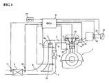
- Fig. 1 shows a schematic layout of exhaust gas passages as well as a controller used in an exhaust system for an internal combustion engine used to propel a vehicle.
- a cylinder head 1a of the internal combustion engine 1 has exhaust ports 2 laterally opening from the first to fourth cylinders (only one is shown in Fig. 1 ), which may be arranged inline.
- Each of the exhaust ports 2 (only one is shown in Fig. 1 ) is connected to a respective upstream portion of a main exhaust gas passage 3.
- the four upstream portions of the main exhaust gas passage 3 (only one is shown in Fig. 1 ), which correspond to the first to fourth cylinders, merge at a portion at which slow path switching valve(s) 5 are disposed to form a single main exhaust gas flow passage, which is a downstream portion of the main exhaust gas passage 3, leading to a main catalytic converter 4.
- the main catalytic converter 4 which is located underneath the vehicle, may have a large capacity and may contain a three-way catalyst as well as a hydro-carbon (HC) trap catalyst.
- Exhaust gas emitted from the exhaust port 2 flows through the upstream portion of the main exhaust gas passage 3, through the portion placed with the flow path switching valves 5, through the downstream portion of the main exhaust gas flow passage 3, to the main catalytic converter 4 for purifying the exhaust gas emitted during a normal engine operation.
- the flow path switching valves 5 may provide a closing means for changing a flow path by permitting or preventing exhaust gas flow through the main exhaust gas passage 3.
- the flow path switching valves 5 (only one is shown in Fig.
- a single flow path switching valve 5 may be disposed after a merge of plural upstream portions of the main exhaust gas passage 3, e.g., four upstream portions of the main exhaust gas passage 3 connected to the first to fourth cylinders.
- the flow path switching valve 5 is driven by an actuator 5a such as an electric motor, an electric solenoid, a vacuum switch, or any equivalent for reconfiguring the flow path switching valve 5.
- a bypass exhaust gas passage 7 (only one is shown in Fig. 1 ) branch off from the corresponding four upstream portions of the main exhaust gas passage 3 at a respective branch point 6.
- the bypass exhaust gas passage 7 has a cross sectional area smaller than that of the main exhaust gas passage 3.
- the branch points 6 i.e., an upstream end of each of the upstream portion of the bypass exhaust gas passage 7; only one is shown in Fig. 1 ) are disposed upstream as far as possible in the corresponding upstream portions of the main exhaust gas passages 3, i.e., as close as possible to the cylinder head 1a.
- the four upstream portions of the bypass exhaust gas passage 7 merge to form a single bypass exhaust gas flow passage, which is a downstream portion of the bypass exhaust gas passage 7, leading to a bypass catalytic converter 8.
- the bypass catalytic converter 8, which may use a three-way catalyst, is disposed immediately after the merge of the four upstream portions of the bypass exhaust gas passage 7.
- the bypass catalytic converter 8 has a capacity smaller than that of the main catalytic converter 4 and contains a catalyst that can be optimally activated at low temperatures.
- the single bypass exhaust gas flow passage extending from an outlet of the bypass catalytic converter 8 connects at the junction 9 of the main exhaust gas passage 3 (i.e., upstream of the inlet to the main catalytic converter 4 and downstream of the flow path switching valve 5). That is, the bypass exhaust gas passage 7 is provided to bypass a section of the main exhaust gas passage 3 that are upstream of the main catalytic converter 4.
- the flow path switching valve 5 may be mounted in this section of the main exhaust gas passages 3.
- a main upstream air-fuel ratio sensor 10 and a main downstream air-fuel ratio sensor 11 are disposed at the inlet and outlet of the main catalytic converter 4, respectively. Further, a bypass upstream air-fuel ratio sensor 12 and a bypass downstream air-fuel ratio sensor 13 are disposed at the inlet and outlet of the bypass catalytic converter 8, respectively.
- the main upstream and downstream air-fuel ratio sensors 10, 11 may perform conventional feedback control of the air-fuel ratio after activating the main catalytic converter 4.
- the engine air-fuel ratio may be controlled, e.g., by controlling the amount of fuel that is injected into the first to fourth cylinders, in response to an output signal from the main upstream air-fuel ratio sensor 10.
- An output signal from the main downstream air-fuel ratio sensor 11 may be used to compensate for any deviations in control characteristics.
- the bypass upstream and downstream air-fuel ratio sensors 12, 13 may perform conventional feedback control of the air-fuel ratio when the bypass catalytic converter 8 is used. That is to say, when the bypass catalytic converter 8 is used, the engine air-fuel ratio may be controlled in response to an output signal from the bypass upstream air-fuel ratio sensor 12.
- An output signal from the bypass downstream air-fuel ratio sensor 13 may be used to compensate for any deviations in control characteristics.
- the air-fuel ratio sensors 10, 11, 12, 13 may include either broadband air-fuel ratio sensors, which have a substantially linear output characteristic with respect to the air-fuel ratio of the exhaust gas, or oxygen sensors, which have two output characteristics (e.g., indicating either a rich air-fuel ratio or a lean air-fuel ratio).
- broadband air-fuel ratio sensors are used as the upstream air-fuel ratio sensors 10, 12 due to the above-described control characteristics of the air-fuel ratio control, and oxygen sensors are used as the downstream air-fuel ratio sensors 11, 13 to provide a cost benefit.
- the bypass upstream air-fuel ratio sensor 12 may provide a first sensing means for detecting the air-fuel ratio in the bypass exhaust gas flow passage, and the main upstream air-fuel ratio sensor 10 may provide a second sensing means for detecting the air-fuel ratio of an exhaust gas flowing into the main catalytic converter 4 in the main exhaust gas flow passage.
- each of the first to fourth cylinders of the internal combustion engine 1 includes a spark plug 21 (only one is shown in Fig. 1 ), an intake passage 22 (only one is shown in Fig. 1 ), and a fuel injection valve 23 (only one is shown in Fig. 1 ), which may be disposed in the intake passage 22.
- a plenum may be disposed between the intake passages 22 and the throttle valve 24.
- an air flow meter 25 for detecting the amount of intake air used by the engine 1 may be disposed upstream of the throttle valve 24 and downstream of an air cleaner 26.
- An engine control unit 27 controls various parameters of the internal combustion engine 1 (e.g., setting the amount of fuel injected by each fuel injection valve 23, setting the spark timing of each spark plug 21, setting the opening degree of the throttle valve 24, and driving the actuator 5 to set the open/close conditions of the flow path switching valve 5, etc.).
- various parameters of the internal combustion engine 1 e.g., setting the amount of fuel injected by each fuel injection valve 23, setting the spark timing of each spark plug 21, setting the opening degree of the throttle valve 24, and driving the actuator 5 to set the open/close conditions of the flow path switching valve 5, etc.
- output signals from other sensors such as a coolant temperature sensor 28 and a sensor 29 for detecting the position of an accelerator pedal (i.e., stepped degree) operated by the driver, may also be input to the engine control unit 27.
- the engine control unit 27 may also diagnose whether there is a leak at the flow path switching valve 5.
- the flow path switching valve 5 closes the exhaust gas passages 3 in response to a low temperature either of the engine 1 or of the exhaust gas after initiating cold start-up.
- the bypass catalytic converter 8 can be rapidly activated since, for example, it is disposed in close proximity to the exhaust port 2 and it is relatively small in size. This allows the exhaust gas to be purified at an earlier stage after initiating the cold start-up.
- the flow path switching valve 5 opens since the catalyst of the main catalytic converter 4 is fully activated by the heat. As such, most of the exhaust gas discharged from the cylinders passes through the main exhaust gas passage 3, to the main catalytic converter 4. Although the bypass exhaust gas passage 7 are not closed, most of the exhaust gas does not flow through the bypass flow exhaust gas passage 7. Rather, the exhaust gas flows through the main exhaust gas passage 3. This is because the cross-sectional areas of the bypass exhaust gas passage 7 is smaller than that of the exhaust gas passage 3 and by virtue of greater flow resistance due to the bypass catalytic converter 8 being disposed in the bypass exhaust gas flow passage. Because of the differential resistance to flow, thermal deterioration of the bypass catalytic converter 8 may also be avoided.
- the two upstream air-fuel ratio sensors 10, 12 are broadband air-fuel ratio sensors, whereas the two downstream air-fuel ratio sensors 11, 13 are oxygen sensors. Only the two upstream air-fuel ratio sensors 10, 12 are employed when diagnosing leakage in accordance with the first embodiment of the present invention.
- Fig. 2 is a series of graphs illustrating the first embodiment for diagnosing a leak when the flow path switching valve 5 is in a closed-state after initiating cold start-up and the bypass upstream air-fuel ratio sensor 12 provides feedback control of the air-fuel ratio (i.e., after activating the bypass catalytic converter 8).
- the feedback control starts almost immediately after the cold start-up since the bypass catalytic converter 8 can be rapidly activated, as described above.
- the diagnosis may also be performed after activating the main catalytic converter 4 by temporarily closing the flow path switching valve 5.
- Fig 2a is a graph illustrating a comparison between an air-fuel ratio AFB detected by the bypass upstream air-fuel ratio sensor 12 (also referred to hereinafter as the air-fuel ratio AFB), and an air-fuel ratio AFM detected by the main upstream air-fuel ratio sensor 10 (also referred to hereinafter as the air-fuel ratio AFM) during normal conditions, i.e., when there is no leakage and no thermal deterioration of the bypass catalytic converter 8.
- the amount of fuel injection fluctuates periodically to allow the exhaust air-fuel ratio to transition around an ideal air-fuel ratio (i.e., stoichiometric state).
- the air-fuel ratio changes periodically from the stoichiometric state to each of a rich state and a lean state of combustion by the engine 1.
- the bypass upstream air-fuel ratio sensor 12 is directly influenced by the exhaust gas from the engine 1, the output signal corresponding to the fluctuation in the engine air-fuel ratio can be determined. That is, the air-fuel ratio AFB detected by the bypass upstream air-fuel ratio sensor 12 corresponds to the engine air-fuel ratio, or may be regarded as the engine air-fuel ratio itself.
- the graph for the air-fuel ratio AFM detected by the main upstream air-fuel ratio sensor 10 shows that the rich/lean state, which exceeds the ideal air-fuel ratio, can be achieved in a shorter amount of time. It further shows that the change timing, i.e., the point at which there is a change between stoichiometric, rich and lean states, is delayed compared to that of the air-fuel ratio AFB detected by the bypass upstream air-fuel ratio sensor 12. This is due to the oxygen capacity of the catalyst for the bypass catalytic converter 8.
- Oxygen is absorbed when the exhaust air-fuel ratio turns to a lean state and is discharged when the exhaust air-fuel ratio turns to a rich state.
- the exhaust air-fuel ratio periodically fluctuates between rich and lean states, there is no change at the downstream side of the bypass catalytic converter 8 until the oxygen capacity of the bypass catalytic converter 8 is saturated.
- Fig. 2b shows the associated characteristics when there is an exhaust gas leak by the flow path switching valve 5 in its closed-state. Since such leakage does not affect the air-fuel ratio AFB detected by the bypass upstream air-fuel ratio sensor 12, there is no change from the normal state shown in Fig. 2a . However, the main upstream air-fuel ratio sensor 10 detects the exhaust gas that leaks past the flow path switching valve 5, i.e., the exhaust gas that does not pass through the bypass catalytic converter 8. Thus, the detected air-fuel ratio AFM fluctuates between rich and lean states at the same times as when the bypass upstream air-fuel ratio sensor 12 detects the air-fuel ratio AFB.
- the value of the rich/lean state (i.e., the amplitude of the periodic variation) is lower than that of the air-fuel ratio AFB detected by the bypass upstream air-fuel ratio sensor 12. This is due to the dilution that results from the mixture with the exhaust gas that does pass through the bypass catalytic converter 8.
- a time delay ⁇ t may be determined between the time at which a rich state changes to a lean state, or vice-versa, in the air-fuel ratio AFM as detected by the main upstream air-fuel ratio sensor 10 and the corresponding time (i.e., at which rich state changes to lean state, or vice-versa) in the air-fuel ratio AFB as detected by the bypass upstream air-fuel ratio sensor 12. If the time delay ⁇ t is smaller than a threshold value, then the occurrence of leakage is determined.
- an interval t1 of the rich or lean state in the air-fuel ratio AFB detected by the bypass upstream air-fuel ratio sensor 12 may be compared with an interval t2 of the corresponding rich or lean state in the air-fuel ratio AFM detected by the main upstream air-fuel ratio sensor 10. If the intervals t1 and t2 are substantially equal, then the occurrence of leakage is determined.
- determining leakage may include calculating the mean value from a plurality of air-fuel ratio variations, or evaluating the time delay ⁇ t that is substantially equivalent to the difference (t1- t2) between the intervals t1 and t2. Methods using these features will now be described.
- Fig. 2c shows the variation in the air-fuel ratio AFM when the catalyst of the catalytic converter 8 is somewhat deteriorated.
- the fundamental variation in the air-fuel ratio AFM detected by the main upstream air-fuel ratio sensor 10 does not change.
- the rich/lean state fluctuates more quickly. That is, the time delay ⁇ t with respect to the change in the air-fuel ratio AFB detected by the bypass upstream air-fuel ratio sensor 12 becomes shorter.
- the time interval t2 of rich/lean state becomes longer. If the catalyst has deteriorated to the point of zero oxygen capacity, then the time delay ⁇ t or the time intervals t1 and t2 may not be distinguishable from the case shown in Fig.
- catalyst deterioration may be distinguished from determining that there is a leak by the flow path switching valve 5.
- the time delay ⁇ t is less than a first threshold value, then it can be determined that leakage has occurred. However, if the time delay ⁇ t is greater than a second threshold value, then it can be determined that no leakage has occurred. Further, if the time delay ⁇ t falls in a predetermined range, e.g., between third and fourth threshold values that are themselves between the first and second threshold values, then it can be determined that the catalyst in the bypass catalytic converter 8 has deteriorated.
- the third and fourth threshold values may be equal to the first and second threshold values, respectively.
- the leakage of the flow path switching valve 5 can be diagnosed even while a conventional feedback control of the air-fuel ratio continues. Moreover, the toxicity of the exhaust gas is not worsened when such diagnosis is performed. Furthermore, it is possible to perform an accurate leakage diagnosis, including determining whether the catalyst has deteriorated.
- Fig. 3 is a series of graphs illustrating a second embodiment according to the present invention for diagnosing a leak after the bypass catalytic converter 8 is activated when the flow path switching valve 5 is in a closed-state after initiating cold start-up.
- the engine air-fuel ratio is forcibly changed by a feed-forward control (i.e., from rich to lean or vice-versa) at a constant period and amplitude.
- Fig. 3a shows the normal state (no leakage and no catalyst deterioration), whereas Fig. 3b shows the occurrence of leakage, and Fig. 3c shows the deterioration of the catalyst. It should be noted that the diagnosis method is the same as that of the first embodiment.
- the change in the period and amplitude for rich/lean states of the engine air-fuel ratio is not necessarily constant with respect to the driving condition of the engine 1.
- the engine air-fuel ratio changes regularly at a constant period and amplitude. This may enhance the accuracy of diagnosing leakage and catalyst deterioration.
- the rich/lean state is periodically changed with respect to the ideal air-fuel ratio so that the average air-fuel ratio may be maintained near the ideal air-fuel ratio. Therefore, the toxicity of the exhaust gas is not worsened.
- the period for the change in engine air-fuel ratio is set to be not so long as to significantly reduce the oxygen capacity of the catalyst.
- an apparatus for diagnosing an exhaust gas purifying system of an internal combustion engine.
- the apparatus includes bypass exhaust gas passages that are disposed upstream of a main catalytic converter.
- a bypass catalytic converter is provided along the bypass exhaust gas passages, and a flow path switching valve is provided for diverting the exhaust gas through the bypass exhaust gas passage.
- the apparatus also includes a first air-fuel ratio sensor for detecting an air-fuel ratio of the exhaust gas upstream of the bypass catalytic converter, and a second air-fuel ratio sensor for detecting an air-fuel ratio of the exhaust gas upstream of the main catalytic converter.
- the flow path switching valve can be diagnosed for leakage by using detected signals from the first and second sensors when the flow path switching valve is in a closed state.
- leakage by the flow path switching valve can be diagnosed according to the following two steps: (i) determining a time delay in the change between rich and lean states as detected by the second air-fuel ratio sensor with respect to a similar change between states as detected by the first air-fuel ratio sensor; and (ii) determining whether there is leakage based on the time delay.
- leakage by the flow path switching valve can be diagnosed according to the following two steps: (i) determining a time interval in the change between rich and lean states as detected by the second air-fuel ratio sensor and a similar time interval between states as detected by the first air-fuel ratio sensor; and (ii) determining whether there is leakage by comparing the time intervals.
- the engine air-fuel ratio may be periodically changed in a predetermined period during diagnosis. Further, since the average air-fuel ratio is substantially maintained at the ideal air-fuel ratio, even in case of a forcible periodic changes in the engine air-fuel ratio, the toxicity of the exhaust gas is not worsened.
- the diagnosis for determining whether there is any leakage past the flow path switching valve 5 is performed when the flow path switching valve 5 is in the closed position.
- the diagnosis can be performed by using the periodic change in the engine air-fuel ratio in response to feedback control of the air-fuel ratio.
- the signal detected by the first air-fuel ratio sensor 12 is also periodically changed with the engine air-fuel ratio. This is because the first air-fuel ratio sensor 12 is disposed upstream of the bypass catalytic converter 8.
- the air-fuel ratio of the exhaust gas downstream of the bypass catalytic converter 8 varies in a relatively small range, with a time delay relative to the engine air-fuel ratio due to the oxygen capacity of the catalyst.
- the second air-fuel ratio sensor 10 disposed upstream of the main catalytic converter 4 receives only the exhaust gas that has already passed through the bypass catalytic converter 8.
- the air-fuel ratio detected by the second air-fuel ratio sensor 10 varies in a relatively small range, with a time delay relative to the periodic change in the exhaust air-fuel ratio, as described above.
- the air-fuel ratio detected by the second air-fuel ratio sensor 10 varies at approximately the same time as that of the exhaust air-fuel ratio.
- the air-fuel ratio detected by the second air-fuel ratio sensor 10 also varies with respect to the air-fuel ratio detected by the first air-fuel ratio sensor 12.
- oxygen capacity may be influenced by deterioration of the catalyst.
- the change timings between the rich/lean states detected by the first and second air-fuel ratio sensors 12, 10 do not completely coincide with each other. Further, the time delay becomes shorter depending on the deterioration level. Therefore, whether or not the leakage occurs can be determined even if there is catalyst deterioration.
- any leakage by the flow path switching valve 5 can be properly and easily diagnosed, thereby avoiding unpurified exhaust gas from being discharged to the atmosphere during an early stage of engine start-up.
- the average air-fuel ratio may be equal to, or at least closer to, the ideal air-fuel ratio.
- the toxicity of the exhaust emission is not worsened.
- the exhaust system is identical to that of the first embodiment and the arrangement of the exhaust and control systems are identical to those illustrated in Fig. 1 .
- the bypass upstream air-fuel ratio sensor 12 may provide a first air-fuel ratio detecting means
- the main upstream air-fuel ratio sensor 10 may provide a second air-fuel ratio detecting means.
- the main upstream air-fuel ratio sensor 10 is mounted at a section of the main exhaust gas flow passage that is between the junction 9 and the main catalytic converter 4.
- Such a sensor 10 is for detecting the air-fuel ratio for the exhaust gas downstream of the junction 9 at which the bypass exhaust gas flow passage joins the main exhaust gas flow passage.
- the two upstream air-fuel ratio sensors 10, 12 include broadband air-fuel sensors, whereas the two downstream air-fuel ratio sensors 11, 13 include oxygen sensors.
- the engine air-fuel ratio may be changed immediately from rich to lean or vice-versa, only the change from lean to rich will be described.
- Fig. 4 shows a flow chart illustrating the diagnosis process according to the third embodiment.
- the engine angular speed NE e.g., in terms of rotations per minute
- engine load TP e.g., in terms of amount of fuel being injected
- an opening degree TVO of the throttle valve 24 are read (step S1).
- the diagnosis is performed when the bypass catalytic converter 8 is activated, the main catalytic converter 4 is not in a hot temperature atmosphere, and the flow path switching valve 5 is in a closed position.
- step S3 If it is determined that a diagnosis can be performed, then the target air-fuel ratio of the internal combustion engine is set to the lean state (step S3). Then, a stand-by mode occurs until the signal output from the bypass downstream air-fuel sensor 13 is indicative of a lean state (step S4). That is, the engine air-fuel ratio is kept in a lean state until the oxygen capacity of the bypass catalytic converter 8 is saturated. Thereafter, the target air-fuel ratio is changed immediately to a rich state (step S5). Under such conditions, while the changes of the output signals from the bypass upstream air-fuel ratio sensor 12 and the main upstream air-fuel ratio sensor 10 are monitored, a diagnostic parameter (as will be described hereinafter) is calculated (step S6).
- step S7 If the diagnosis for a predetermined time period is completed after setting the target air-fuel ratio to the rich state (step S7), then the target air-fuel ratio is reverted to the ideal air-fuel ratio (step S8). Then, the diagnostic parameter is compared with a threshold value L for determining leakage (step S9). Whether the diagnosis is completed can be determined based on, for example, the elapsed time from changing to the rich state (step S5). Alternatively, the diagnosis can be completed when the output signal of the bypass downstream air-fuel ratio sensor 13 is indicative of a rich state.
- step S9 if it is determined that the diagnostic parameter is greater than the threshold value L, then leakage by the flow path switching valve 5 is determined to have occurred, and an alert may be generated, e.g., activating a warning lamp (not shown), to notify the vehicle operator or vehicle service personnel that an error condition exists (step S10).
- a warning lamp not shown
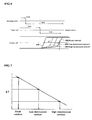
- Fig. 5 which is a time chart for determining leakage, shows the following: changes in the target engine air-fuel ratio of the internal combustion engine 1, the output signal of the bypass downstream air-fuel ratio sensor 13, the air-fuel ratio AFM detected by the main upstream air-fuel ratio sensor 10, and the air-fuel ratio AFB detected by the bypass upstream air-fuel ratio sensor 12.
- the target engine air-fuel ratio is forcibly changed into a lean state from the ideal air-fuel ratio for purposes of diagnosis and then changed immediately to a rich state. Then, since the flow path switching valve 5 is closed, the exhaust gas flows through the bypass exhaust gas passage 7 and oxygen is stored in the catalyst of the bypass catalytic converter 8 during the lean state.
- the air-fuel ratio AFB detected by the bypass upstream air-fuel ratio sensor 12 disposed upstream of the bypass catalytic converter 8 is immediately changed to the rich state.
- the air-fuel ratio AFM detected by the main upstream air-fuel ratio sensor 10 is not immediately changed, i.e., it changes to the rich state after a time delay as indicated by a solid line. That is, as shown by the solid line, when there is no leakage, the air-fuel ratio AFB detected by the bypass upstream air-fuel ratio sensor 12 is significantly different from the air-fuel ratio AFM detected by the main upstream air-fuel sensor 10.
- the air-fuel ratio AFM detected by the main upstream air-fuel ratio sensor 10 indicates a relatively richer state as indicated by a chain line.
- the air-fuel ratio AFM detected by the main upstream air-fuel sensor 10 is relatively closer to the air-fuel ratio AFB detected by the bypass upstream air-fuel ratio sensor 12 depending on the level of the leakage.
- the output signal of the bypass downstream air-fuel ratio sensor 13 indicates a lean state having a predetermined level, and the target engine air-fuel ratio is changed bask to the ideal air-fuel ratio at this stage.
- whether or not there is any leakage can be determined based on the output signal from the main upstream air-fuel ratio sensor 10 and the bypass upstream air-fuel ratio sensor 12. Such a determination can be made after the engine air-fuel ratio changes between the lean or rich states with respect to the ideal air-fuel ratio, which is interposed between the lean or rich states. Specifically, the diagnosis can be conducted by using the change timing of the detected air-fuel ratio or the difference in the detected air-fuel ratios (as will be described hereinafter).
- the above-mentioned diagnostic parameter may be determined as a difference between the average values, i.e., AVAFM-AVAFB.
- the diagnostic parameter is then compared with the predetermined threshold value L.
- the threshold value L may be predetermined according to the leakage level to be detected.
- the threshold value should be set to a greater value (however, more detection errors are likely to occur with a greater threshold value).
- the time period T may be set, for example, to include the entire time period during which the target engine air-fuel ratio is in a lean state, or to include only a portion of the entire time period.
- the diagnosis which uses the diagnostic parameter based on the detected air-fuel ratios, provides the following effects.
- a broadband air-fuel ratio sensor can be very sensitive to even a small change in the air-fuel ratio
- its output signal can change immediately in response to even a small change in the exhaust air-fuel ratio without any leakage (even downstream of the catalyst; see Fig. 5 ). Therefore, it may be difficult to perform a diagnosis based solely on the change timing of the output signals.
- the average values of the air-fuel ratios detected during the predetermined interval are particularly useful as the diagnostic parameter.
- the accuracy of the diagnosis may be improved as compared to using the time difference with only one set of points according to the change timing method.
- any leakage by the flow path switching valve 5 may be easily diagnosed by using conventional air-fuel ratio sensors 10, 11, 12, 13, which are otherwise provided for the conventional feedback control of the air-fuel ratio. Therefore, without additional sensors, it is possible to avoid unnecessarily toxic exhaust gas emissions due to sealing defects or the like in the flow path switching valve 5.
- oxygen can be fully stored in the catalyst up to a saturated state or the catalyst can be maintained at an oxygen-empty state until the air-fuel ratio is changed from lean to rich states, and vice-versa, with respect to the ideal air-fuel ratio. This may increase the accuracy of the diagnosis since it can maximize the difference between the detected air-fuel ratios.
- a proper time delay is given after the output signal from the bypass downstream air-fuel ratio sensor 13 indicates a lean state, and the engine air-fuel ratio is initially set to the lean state to increase the amount of oxygen stored in the catalyst of the bypass catalytic converter 8. As such, the catalyst can be in a fully saturated state. Further, unpurified HC is not discharged until the oxygen is saturated.
- the main upstream air-fuel ratio sensor 10 indicates a change to the lean state after a time delay. If the main upstream air-fuel ratio sensor 10 rapidly changes to the lean state, then there is leakage.
- the above diagnosis depends on the oxygen capacity of the catalyst in the bypass catalytic converter 8, such diagnosis may be influenced if the oxygen capacity is lowered due to deterioration of the catalyst.
- the threshold value L may be a constant value, it is helpful to adjust the threshold value according to the level of catalyst deterioration, and thereby increase the accuracy of the diagnosis.
- Fig. 6 is a time chart illustrating a method for diagnosing the catalyst deterioration level of the bypass catalytic converter 8. Such diagnosis method is performed in an open condition of the flow path switching valve 5.
- the flow path switching valve 5 may be forcibly opened for purposes of diagnosing the catalyst deterioration.
- the target air-fuel ratio of the internal combustion engine 1 is changed immediately from the lean state to the rich state in the open condition of the flow path switching valve 5.
- the time difference ⁇ T is then measured.
- the time difference ⁇ T refers to a difference between the times for the change of state of the air-fuel ratio AFM as detected by the main upstream air-fuel ratio sensor 10 and the change of state of the air-fuel ratio AFB as detected by the bypass downstream air-fuel ratio 13.
- the air-fuel ratio AFM as detected by the main upstream air-fuel ratio sensor 10 immediately indicates a rich state. This is because the flow path switching valve 5 is in the open-state, while the air-fuel ratio AFB detected by the bypass downstream air-fuel ratio 13 (also referred to as a third means for detecting an exhaust air-fuel ratio downstream of the bypass catalytic converter 8) changes to indicate a rich state after a time delay due to the oxygen capacity of the catalyst.
- the bypass catalytic converter 8 is relatively new with no deterioration, the time difference ⁇ T becomes large. The time difference ⁇ T becomes smaller as the level of deterioration increases.
- the catalyst deterioration level can be determined from the time difference ⁇ T. Moreover, the catalyst deterioration level can be measured, for example, by using the change in the air-fuel ratio during a so-called “fuel cut-off and recovery” process, wherein the fuel is cut-off during deceleration and is recovered after the fuel is cut-off.
- the threshold value L can be determined, for example, by using the catalyst deterioration level. As a result, the threshold value L may be adjusted to reflect the catalyst deterioration level. Hence, the diagnosis of leakage can be accurately performed. Insofar as the diagnosis of catalyst deterioration level is performed in an open condition of the flow path switching valve 5, it is possible to accurately determine whether or not the leakage occurs in the flow path switching valve 5. This is because the valve-opened state enables the catalyst deterioration level to be measured without being influenced by any leakage. Further, whether or not the leakage occurs can be determined based on the measured catalyst deterioration level. Although a linear characteristic is schematically shown in Figs. 7 and 8 , nonlinear characteristics are also envisioned. Additionally, alternative methods may be used to diagnosis the level of catalyst deterioration.
- an exhaust gas purifying system includes the bypass exhaust gas passage 7 provided upstream of the main exhaust gas flow passage leading to the main catalytic converter 4.
- the bypass exhaust gas passage 7 lead to the bypass catalytic converter 8.
- a flow path switching valve 5 for blocking exhaust gas flow is provided upstream of the main exhaust gas flow passage.
- the purifying system includes a first air-fuel ratio detection means for detecting an exhaust air-fuel ratio upstream of the bypass catalytic converter 8, a second air-fuel ratio detection means for detecting an exhaust air-fuel ratio upstream of the main catalytic converter 4, an air-fuel ratio control means for changing immediately an engine air-fuel ratio between lean and rich states with respect to the ideal air-fuel ratio when the flow path switching valve 5 is in a closed condition, and a diagnostic means for diagnosing whether there is any leakage by the flow path switching valve 5 based on the air-fuel ratios detected by the first and second air-fuel ratio detection means after the immediate changes of the engine air-fuel ratio.
- the immediate change of the engine air-fuel ratio is from the lean state to the rich state, while maintaining a sufficient time necessary for saturating the oxygen in the bypass catalytic converter 8.
- Diagnosing whether the flow path switching valve 5 is leaking may be performed by changing the engine air-fuel ratio, e.g., from lean state to rich state, when the flow path switching valve 5 is set to be in the closed condition.
- excess oxygen during the lean state of the engine air-fuel ratio is stored in the catalyst according to the oxygen capacity of the bypass catalytic converter 8.
- oxygen is discharged when the engine air-fuel ratio is set to the rich state.
- the air-fuel ratio detected by the second air-fuel ratio detection means does not immediately indicate a rich state due to the influence of the discharging oxygen so long as the flow path switching valve 5 is not leaking.
- the exhaust air-fuel ratio detected by the second air-fuel ratio detection means is relatively leaner than the engine air-fuel ratio immediately after changing the engine air-fuel ratio.
- the flow path switching valve 5 when the flow path switching valve 5 is leaking, the exhaust air-fuel ratio detected by the second air-fuel ratio detecting means can be even leaner due to the relatively rich state of the leaked exhaust gas. Therefore, leakage by the flow path switching valve and the level of such leakage may be determined by using these factors.
- the leakage diagnosis may also be influenced by the oxygen capacity of the bypass catalytic converter 8.
- determining whether or not there is a leak depends on the difference between the average air-fuel ratios detected by the first and second air-fuel ratio detection means after the immediate changes in the engine air-fuel ratio.
- the oxygen capacity may be influenced by the catalyst deterioration level.
- a catalyst deterioration detecting means for measuring the catalyst deterioration level. This is so that the leakage diagnosis can be corrected or adjusted for according to the catalyst deterioration level.
- the threshold value when such diagnosis is performed by comparing the difference between the average air-fuel ratios to the threshold value, the threshold value may be modified depending on the catalyst deterioration level. By doing so, the accuracy of the diagnosis can be enhanced.
- determining at an early stage whether the flow path switching valve 5 is leaking may help to avoid the discharge of unpurified exhaust gas to the atmosphere.
- adjusting the diagnosis to reflect the catalyst deterioration level may improve the accuracy of the diagnosis.
- the exhaust system of the fourth embodiment is the same as that of the first embodiment, and the arrangement of the exhaust gas passages and the control system of exhaust system is identical to that illustrated in Fig. 1 .
- the bypass downstream air-fuel ratio sensor 13 provides a first air-fuel ratio detecting means
- the main upstream air-fuel ratio sensor 10 provides a second air-fuel ratio detecting means.
- the main upstream air-fuel ratio sensor 10 is mounted at a section of the main exhaust gas flow passage that is between the junction 9 and the main catalytic converter 4.
- the sensor 10 is for detecting the air-fuel ratio of exhaust gas downstream of the junction 9 at which the bypass exhaust gas flow passage joins the main exhaust gas flow passage.
- the bypass upstream air-fuel sensor 12 includes a broadband air-fuel sensor, whereas the three air-fuel ratio sensors 10, 11, 13 include oxygen sensors.
- the engine air-fuel ratio may be immediately changed between the rich and lean states, only the change from the lean state to the rich state will be described.
- the diagnosis process is identical to that of the second embodiment. Further, the relevant flow chart showing the diagnosis process of this embodiment is identical to that illustrated in Fig. 4 .
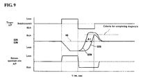
- Fig. 9 which is a time chart illustrating the diagnosis of the fourth embodiment, shows the following: the change of the target air-fuel ratio of the internal combustion engine, the output signal O2B from the bypass downstream air-fuel ratio sensor 13 and the output signal O2M from the main upstream air-fuel ratio sensor 10, and the air-fuel ratio detected by the bypass upstream air-fuel ratio sensor 12. Further, Fig. 9 illustrates a case when leakage occurs from the flow path switching valve 5 (as will be described hereinafter). As was previously described for the purpose of diagnosing leakage, the target engine air-fuel ratio is forcibly changed to a lean state from the ideal air-fuel ratio, and is then immediately changed to a rich state.
- the bypass upstream air-fuel ratio sensor 12 immediately begins to indicate a lean state of the exhaust air-fuel ratio with respect to the engine air-fuel ratio.
- the target engine air-fuel ratio is changed to the rich state with a time delay after the signal O2B from the bypass downstream air-fuel ratio sensor 13 indicates the lean state.
- the air-fuel ratio detected by the bypass upstream air-fuel ratio sensor 12 disposed upstream of the bypass catalytic converter 8 immediately begins to change to indicate the rich state. Since the oxygen stored in the bypass catalytic converter 8 is discharged downstream of the bypass catalytic converter 8, the output signal O2B from the bypass downstream air-fuel ratio sensor 10 reverts to indicating the rich state with a time delay after the engine air-fuel ratio turns to the rich state. Further, unless exhaust gas is leaking by the flow path switching valve 5, the output signal 02M from the main upstream air-fuel ratio sensor 10 almost simultaneously reverts to indicating the rich state.
- both of the output signals O2B, O2M simultaneously revert from indicating a rich state to indicating a lean state if no leakage occurs.
- the output signal O2M from the main upstream air-fuel ratio sensor 10 reverts to indicating a rich state, as shown in Fig. 9 . That is, when leakage does occur, the difference increases between the change timings to the rich state of the output signal O2M from the main upstream air-fuel ratio sensor 10 and the output signal O2B from the bypass downstream air-fuel ratio sensor 13. Further, the target air-fuel ratio returns to the ideal air-fuel ratio when the output signal O2B from the bypass downstream air-fuel ratio sensor 13 reaches a predetermined level (corresponding to the lean state) and all the oxygen stored in the catalyst is discharged.
- whether or not the leakage occurs can be determined based on the output signals from the main upstream air-fuel ratio sensor 10 and the bypass upstream air-fuel ratio sensor 12. Such a determination can be made after the engine air-fuel ratio is immediately changed between the lean and the rich states with respect to the ideal air-fuel ratio interposed between the lean and the rich states. More specifically, the diagnosis can be performed by using the output difference or the time difference between the changes in the output (as will be described hereinafter).
- the level of leakage may be represented using numerical values based on determining the points of time when the output signals O2M, O2B from the main upstream air-fuel ratio sensor 10 and the bypass downstream air-fuel ratio 13, respectively, revert to the rich state from the lean state across an intermediate reference voltage V0 (shown in Fig. 9 ).
- the time difference ⁇ T between both points of time i.e., the time delay of the change in the output signal O2B with respect to the change in the output signal O2M
- the diagnostic parameter is compared with a predetermined threshold value L for determining leakage.
- the threshold value L is predetermined according to the leakage level to be detected. If it is desirable for the diagnosis to detect a slight level of leakage, then the threshold value may be set lower (however, more detection errors may occur when the threshold value is low). Accordingly, when the time difference ⁇ T is large, it is determined that leakage has occurred.
- a diagnosis based on the time difference ⁇ T has the following effects. Since the output of the oxygen sensor rapidly changes according to the particular condition (i.e., lean state or rich state), a large output difference may be easily detected even when no actual leakage occurs. This is because the change timings of the outputs are inconsistent with each other due to the relative positions of the sensors in the exhaust system (i.e., relatively upstream or downstream). However, as described above, the time difference ⁇ T provides a diagnostic parameter that appears more distinct with regard to whether or not leakage occurs. Thus, the diagnosis accuracy can be further enhanced as compared to using the output difference.
- oxygen can be fully stored in the catalyst up to a saturated state or the catalyst can be maintained at an oxygen-empty state until the air-fuel ratio is changed from lean to rich states, and vice-versa, with respect to the ideal air-fuel ratio interposed between the lean and rich states. This may increase the accuracy of the diagnosis since it can maximize the difference between the detected air-fuel ratios.
- a proper time delay is given after the output signal from the bypass downstream air-fuel ratio sensor 13 indicates a lean state, and the engine air-fuel ratio is initially set to the lean state to increase the amount of oxygen stored in the catalyst of the bypass catalytic converter 8. As such, the catalyst can be in a fully saturated state. Further, unpurified HC is not discharged until the oxygen is saturated.
- the main upstream air-fuel ratio sensor 10 indicates a change to the lean state after a time delay. If the main upstream air-fuel ratio sensor 10 rapidly changes to the lean state, then there is leakage.
- the above diagnosis depends on the oxygen capacity of the catalyst in the bypass catalytic converter 8 (similar to the second embodiment), such diagnosis may be influenced if the oxygen capacity is lowered due to deterioration of the catalyst.
- the threshold value L may be a constant value, it may be useful to adjust the threshold value according to the level of catalyst deterioration level, and thereby increase the accuracy of the diagnosis.
- the method of the second embodiment with reference to Fig. 6 may be employed as the diagnosis method for the catalyst deterioration level of the bypass catalytic converter 8.
- the threshold value L can be determined, for example, based on the catalyst deterioration level. As a result, the threshold value L may reflect the catalyst deterioration level. Hence, the diagnosis of leakage can be accurately performed. Insofar as the diagnosis of catalyst deterioration level is conducted in an open condition of the flow path switching valve 5, it is possible to accurately determine whether or not the leakage occurs in the flow path switching valve 5. This is because the valve-opened state enables the catalyst deterioration level to be measured without being influenced by any leakage. Further, whether or not the leakage occurs can be determined based on the measured catalyst deterioration level. Additionally, alternative methods may be used to diagnosis the level of catalyst deterioration.
- an exhaust gas purifying system includes bypass exhaust gas passage 7 provided upstream of the main exhaust gas flow passage leading to the main catalytic converter 4.
- the bypass exhaust gas passage 7 lead to the bypass catalytic converter 8.
- a flow path switching valve 5 for blocking exhaust gas flow is provided upstream of the main exhaust gas flow passage.
- the purifying system includes a first air-fuel ratio detection means for detecting an exhaust air-fuel ratio downstream of the bypass catalytic converter 8, a second air-fuel ratio detection means for detecting an exhaust air-fuel ratio upstream of the main catalytic converter 4, an air-fuel ratio control means for changing immediately an engine air-fuel ratio between lean and rich states with respect to the ideal air-fuel ratio when the flow path switching valve 5 is in a closed condition, and a diagnostic means for diagnosing whether there is any leakage by the flow path switching valve 5 based on the air-fuel ratios detected by the first and second air-fuel ratio detection means after the immediate changes of the engine air-fuel ratio.
- the immediate change of the engine air-fuel ratio is from the lean state to the rich state, while maintaining a sufficient time necessary for saturating the oxygen in the bypass catalytic converter 8.
- Diagnosing whether the flow path switching valve 5 is leaking may be performed by changing the engine air-fuel ratio, e.g., from lean state to rich state, when the flow path switching valve 5 is set to be in the closed condition.
- excess oxygen during the lean state of the engine air-fuel ratio is stored in the catalyst according to the oxygen capacity of the bypass catalytic converter 8.
- oxygen is discharged when the engine air-fuel ratio is set to the rich state.
- the air-fuel ratio detected by the first and second air-fuel ratio detection means do not immediately indicate a rich state due to the influence of the discharging oxygen so long as the flow path switching valve 5 is not leaking.
- the exhaust air-fuel ratio detected by the second air-fuel ratio detection means is relatively leaner than the engine air-fuel ratio immediately after changing the engine air-fuel ratio.
- the flow path switching valve 5 when the flow path switching valve 5 is leaking, the exhaust air-fuel ratio detected by the second air-fuel ratio detecting means can be even leaner due to the relatively rich state of the leaked exhaust gas. Therefore, leakage by the flow path switching valve and the level of such leakage may be determined by using these factors.
- the leakage diagnosis may be influenced by the oxygen capacity of the bypass catalytic converter 8.
- the diagnosis of the flow path switching valve 5 is performed by changing the engine air-fuel ratio, e.g., from a lean state to a rich state, when the flow path switching valve 5 is set to be in a closed-state.
- excess oxygen during the lean state of the engine air-fuel ratio is stored in the catalyst due the oxygen capacity of the bypass catalytic converter 8.
- oxygen is discharged when the engine air-fuel ratio transitions to the rich state.
- the air-fuel ratios detected by the first and second air-fuel ratio detection means are not immediately turned to the rich state. This is due to the oxygen being discharged so long as the flow path switching valve 5 does not leak.
- the air-fuel ratios detected by the first and second air-fuel detection means indicate a rich state at approximately the same time.
- the exhaust air-fuel ratio detected by the second air-fuel ratio detecting means immediately indicates a lean state since the leaking exhaust gas is in a rich state. Therefore, whether or not the flow path switching valve 5 is leaking, and the level of such leakage, may be determined based on these factors.
- the influence of leakage may be due to the oxygen capacity.
- determining whether or not leakage occurs is performed based on a difference between the change timings of the air-fuel ratios detected by the first and second air-fuel ratio detection means after immediately changing the engine air-fuel ratio.
- the oxygen capacity may be influenced by the catalyst deterioration level.
- a catalyst deterioration detecting means for measuring the catalyst deterioration level. This is so that the leakage diagnosis can be corrected or adjusted for according to the catalyst deterioration level.
- the threshold value when the leakage diagnosis is performed by comparing the threshold value with time delay of the change timing of the air-fuel ratio detected by the first air-fuel ratio detection means with respect to the change timing of the air-fuel ratio detected by the second air-fuel ratio detection means after the engine air-fuel ratio is changed immediately, the threshold value may be modified depending on the catalyst deterioration level. As such, the accuracy of the diagnosis can be increased.
- determining at an early stage whether the flow path switching valve 5 is leaking may avoid the discharge of unpurified exhaust gas to the atmosphere.
- adjusting the diagnosis to reflect the catalyst deterioration level may improve the accuracy of the diagnosis.
Landscapes
- Engineering & Computer Science (AREA)
- Chemical & Material Sciences (AREA)
- Combustion & Propulsion (AREA)
- Mechanical Engineering (AREA)
- General Engineering & Computer Science (AREA)
- Chemical Kinetics & Catalysis (AREA)
- Health & Medical Sciences (AREA)
- Toxicology (AREA)
- Materials Engineering (AREA)
- Exhaust Gas After Treatment (AREA)
Claims (17)
- Gerät, das Folgendes aufweist:eine Hauptabgaspassage (3);einen Hauptkatalysator (4), der in der Hauptabgaspassage (3) angeordnet ist;eine Bypassabgaspassage (7) in Fluidverbindung mit der Hauptabgaspassage (3), um einen Abschnitt davon zwischen einer Abzweigstelle (6), an der sich die Bypassabgaspassage (7) aus der Hauptabgaspassage (3) verzweigt, und einer Verbindungsstelle (9), an der die Bypassabgaspassage (7) mit der Hauptabgaspassage (3) an einer stromaufwärtigen Seite des Hauptkatalysators (4) zusammenfließt, zu umgehen;einen Bypasskatalysator (8), der in der Bypassabgaspassage (7) angeordnet ist;ein Ventil (5), das in dem Abschnitt der Hauptabgaspassage (3) vorgesehen ist, um den Abschnitt der Hauptabgaspassage (3) zu öffnen oder zu schließen;einen ersten Sensor (12), der in der Bypassabgaspassage (7) angeordnet ist, um ein erstes Signal auszugeben, das ein erstes Luft-Kraftstoffverhältnis eines Abgases, das in die Bypassabgaspassage (7) strömt, anzeigt, wobei der erste Sensor (12) eingerichtet ist, um das erste Luft-Kraftstoffverhältnis von Abgas stromaufwärts des Bypasskatalysators (8) zu erfassen;einen zweiten Sensor (10), der in der Hauptabgaspassage (3) zum Ausgeben eines zweiten Signals, das ein zweites Luft-Kraftstoffverhältnis eines Abgases, das in den Hauptkatalysator (4) strömt, anzeigt, angeordnet ist;Steuermittel (27) zum Empfangen des ersten und des zweiten Signals und zum Bestimmen basierend auf dem ersten und dem zweiten Signal, ob das Ventil (5) in der geschlossenen Konfiguration Abgas durch den Abschnitt der Hauptabgaspassage (3) leckt.
- Gerät nach Anspruch 1, wobei der zweite Sensor (10) eingerichtet ist, um das zweite Luft-Kraftstoffverhältnis von Abgas stromabwärts des Ventils (5) zu erfassen.
- Gerät nach Anspruch 1 oder Anspruch 2, wobei das erste Signal Änderungen zwischen dem fetten und dem mageren Zustand des ersten Luft-Kraftstoffverhältnisses von Abgas, das durch die Bypassabgaspassage (7) durchgeht, anzeigt, und das zweite Signal Änderungen zwischen dem fetten und dem mageren Zustand des zweiten Luft-Kraftstoffverhältnisses von Abgas, das durch die Hauptabgaspassage (3) durchgeht, anzeigt.
- Gerät nach Anspruch 3, wobei das Bestimmen, ob das Ventil (5) in der geschlossenen Konfiguration leckt, eine zeitliche Verzögerung zwischen dem ersten Signal, das Änderungen zwischen dem fetten und dem mageren Zustand des ersten Luft-Kraftstoffverhältnisses anzeigt, und dem zweiten Signal, das Änderungen zwischen dem fetten und dem mageren Zustand des zweiten Luft-Kraftstoffverhältnisses anzeigt, aufweist, wobei die zeitliche Verzögerung die Reaktion auf periodische Änderungen eines Motor-Luft-Kraftstoffverhältnisses, das zu dem Verbrennungsmotor geliefert wird, ist.
- Gerät nach Anspruch 3 oder Anspruch 4, wobei das Bestimmen, ob das Ventil (5) in der geschlossenen Konfiguration leckt, das Vergleichen eines ersten Intervalls, während welchem das erste Signal entweder in dem fetten oder dem mageren Zustand des ersten Luft-Kraftstoffverhältnisses bleibt, mit einem zweiten Intervall, während welchem das zweite Signal entweder in dem fetten oder in dem mageren Zustand des zweiten Luft-Kraftstoffverhältnisses bleibt, aufweist, wobei die Änderungen zwischen dem fetten und dem mageren Zustand des ersten und des zweiten Luft-Kraftstoffverhältnisses die Reaktion auf periodische Änderungen eines Motor-Luft-Kraftstoffverhältnisses, das zu dem Verbrennungsmotor geliefert wird, sind.
- Gerät nach einem der Ansprüche 3 bis 5, wobei das Bestimmen, ob das Ventil (5) in der geschlossenen Konfiguration leckt, das periodische Ändern eines Motor-Luft-Kraftstoffverhältnisses, das zu dem Verbrennungsmotor geliefert wird, aufweist, wobei das Motor-Luft-Kraftstoffverhältnis zwischen dem fetten und dem mageren Zustand in Bezug auf ein stöchiometrisches Motor-Luft-Kraftstoffverhältnis geändert wird.
- Gerät nach Anspruch 1, wobei das Steuermittel (27) eingerichtet ist, um eine sofortige Änderung eines Motor-Luft-Kraftstoffverhältnisses zwischen dem mageren und dem fetten Zustand auszuführen, wobei das erste und das zweite Signal jeweils das erste Luft-Kraftstoffverhältnis und das zweite Luft-Kraftstoffverhältnis nach der sofortigen Änderung anzeigen.
- Gerät nach Anspruch 7, wobei das erste Signal einen mittleren Zustand des ersten Luft-Kraftstoffverhältnisses, das von dem ersten Sensor (12) erfasst wird, anzeigt, das zweite Signal einen mittleren Zustand des zweiten Luft-Kraftstoffverhältnisses, der von dem zweiten Sensor (10) erfasst wird, anzeigt, und die mittleren Zustände des ersten und des zweiten Luft-Kraftstoffverhältnisses während einer vorbestimmten Zeitspanne nach dem Ändern des Motor-Luft-Kraftstoffverhältnisses bestimmt werden.
- Gerät nach Anspruch 7 oder Anspruch 8, wobei der zweite Sensor (10) eingerichtet ist, um das zweite Luft-Kraftstoffverhältnis von Abgas stromabwärts der Bypassabgaspassage (7) zu erfassen.
- Gerät nach Anspruch 7 oder irgendeinem Anspruch, der von Anspruch 7 abhängt, wobei die sofortige Änderung des Motor-Luft-Kraftstoffverhältnisses die von dem mageren Zustand auf den fetten Zustand ist.
- Gerät nach Anspruch 10, wobei die sofortige Änderung des Motor-Luft-Kraftstoffverhältnisses nach einer ausreichenden Zeitspanne zum Annähern der Sauerstoffsättigung in dem Bypasskatalysator (8) auftritt.
- Gerät nach Anspruch 7 oder irgendeinem Anspruch, der von Anspruch 7 abhängt, wobei das Steuermittel (27) eingerichtet ist, um ein Katalysatorverschlechterungsniveau des Bypasskatalysators (8) zu bestimmen und das Bestimmen, ob das Ventil (5) in der geschlossenen Konfiguration leckt, basierend auf dem Katalysatorverschlechterungsniveau des Bypasskatalysators (8) einzustellen.
- Gerät nach Anspruch 12, das einen dritten Sensor (13) aufweist, der in der Bypassabgaspassage (7) angeordnet ist, wobei der dritte Sensor (13) ein drittes Luft-Kraftstoffverhältnis von Abgas stromabwärts des Bypasskatalysators (8) erfasst, und der dritte Sensor ein drittes Signal ausgibt, das das dritte Luft-Kraftstoffverhältnis anzeigt, wobei das Steuermittel (27) eingerichtet ist, um das dritte Signal zu empfangen und das Katalysatorverschlechterungsniveau basierend auf Änderungen in dem zweiten und dritten Luft-Kraftstoffverhältnis als Reaktion auf die Änderung des Motor-Luft-Kraftstoffverhältnisses, wenn das Ventil (5) in der offenen Konfiguration ist, zu bestimmen.
- Gerät nach Anspruch 13, wobei das Bestimmen, ob das Ventil (5) in der geschlossenen Konfiguration leckt, Folgendes aufweist
Bestimmen, ob ein Zeitunterschied auftritt zwischen, wenn das erste Signal eine Änderung zwischen dem fetten und dem mageren Zustand des ersten Luft-Kraftstoffverhältnisses anzeigt, und, wenn das zweite Signal eine Änderung zwischen dem fetten und dem mageren Zustand des zweiten Luft-Kraftstoffverhältnisses anzeigt, wobei der Zeitunterschied die Reaktion auf eine Änderung des Motor-Luft-Kraftstoffverhältnisses ist;
Vergleichen eines Schwellenwerts mit dem Zeitunterschied; und
Ändern des Schwellenwerts basierend auf dem Katalysatorverschlechterungsniveau des Bypasskatalysators (8). - Verfahren zur Diagnose eines Abgasreinigungssystems für einen Verbrennungsmotor, wobei das Verfahren Folgendes aufweist:Erfassen eines zweiten Luft-Kraftstoffverhältnisses von Abgas, das durch eine Hauptabgaspassage (3), die einen Hauptkatalysator (4) aufweist, durchgeht;Erfassen eines ersten Luft-Kraftstoffverhältnisses von Abgas, das durch eine Bypassabgaspassage (7) stromaufwärts eines Bypasskatalysators (8), der in der Bypassabgaspassage (7) enthalten ist, durchgeht, wobei die Bypassabgaspassage (7) in Fluidverbindung mit der Hauptabgaspassage (3) ist, um einen Abschnitt davon zwischen einer Abzweigstelle (6), an der die Bypassabgaspassage (7) aus der Hauptabgaspassage (3) abzweigt, und einer Verbindungsstelle (9), an der die Bypassabgaspassage (7) mit der Hauptabgaspassage (3) an einer stromaufwärtigen Seite des Hauptkatalysators (4) zusammenfließt, umzuleiten;Verhindern von Abgasströmung entlang der Hauptabgaspassage (3) mit einem Ventil (5); undbasierend auf dem ersten und dem zweiten Luft-Kraftstoffverhältnis, Bestimmen, ob Abgas durch das Ventil (5) leckt.
- Verfahren nach Anspruch 15, wobei das Erfassen des ersten Luft-Kraftstoffverhältnisses von Abgas das Erfassen eines Luft-Kraftstoffverhältnisses von Abgas aufweist, das in den Bypasskatalysator (8) eintritt, und das Erfassen des zweiten Luft-Kraftstoffverhältnisses von Abgas das Erfassen eines Luft-Kraftstoffverhältnisses von Abgas, das in den Hauptkatalysator (4) eintritt, aufweist.
- Fahrzeug, das ein Gerät nach einem der vorhergehenden Ansprüche aufweist bzw. angepasst ist, um ein Verfahren nach einem der vorhergehenden Ansprüche zu verwenden.
Applications Claiming Priority (3)
| Application Number | Priority Date | Filing Date | Title |
|---|---|---|---|
| JP2006070232A JP4779730B2 (ja) | 2006-03-15 | 2006-03-15 | 内燃機関の排気浄化装置の故障診断装置 |
| JP2006072001A JP4631759B2 (ja) | 2006-03-16 | 2006-03-16 | 内燃機関の排気浄化装置の故障診断装置 |
| JP2006072004A JP4702124B2 (ja) | 2006-03-16 | 2006-03-16 | 内燃機関の排気浄化装置の故障診断装置 |
Publications (3)
| Publication Number | Publication Date |
|---|---|
| EP1835140A2 EP1835140A2 (de) | 2007-09-19 |
| EP1835140A3 EP1835140A3 (de) | 2010-06-30 |
| EP1835140B1 true EP1835140B1 (de) | 2013-07-24 |
Family
ID=38140208
Family Applications (1)
| Application Number | Title | Priority Date | Filing Date |
|---|---|---|---|
| EP07104230.3A Not-in-force EP1835140B1 (de) | 2006-03-15 | 2007-03-15 | Abgasreinigungssystem und dazugehöriges Diagnoseverfahren |
Country Status (3)
| Country | Link |
|---|---|
| US (1) | US8341937B2 (de) |
| EP (1) | EP1835140B1 (de) |
| KR (1) | KR100905811B1 (de) |
Families Citing this family (24)
| Publication number | Priority date | Publication date | Assignee | Title |
|---|---|---|---|---|
| US7536999B2 (en) * | 2007-01-12 | 2009-05-26 | Nissan Motor Co., Ltd. | Air-fuel ratio control apparatus |
| JP4905291B2 (ja) | 2007-08-09 | 2012-03-28 | 日産自動車株式会社 | 空燃比制御装置 |
| DE102007049171B4 (de) * | 2007-10-13 | 2020-12-17 | Bayerische Motoren Werke Aktiengesellschaft | Abgasstrang für eine Brennkraftmaschine mit diagnosefähigem Absperrventil sowie diagnosefähiges Absperrventil |
| DE102007053932A1 (de) * | 2007-11-13 | 2009-05-14 | Bayerische Motoren Werke Aktiengesellschaft | Abgasanlage und Verfahren zum Betreiben derselben |
| JP2010084750A (ja) * | 2008-09-04 | 2010-04-15 | Denso Corp | 排気浄化用触媒の劣化診断装置 |
| US8490383B2 (en) * | 2009-09-14 | 2013-07-23 | Fev Gmbh | Exhaust system for internal combustion engine |
| US8955498B2 (en) * | 2012-07-24 | 2015-02-17 | Ford Global Technologies, Llc | Variable valve timing for EGR control |
| US9500113B2 (en) * | 2014-03-28 | 2016-11-22 | Honda Motor Co., Ltd. | Aftermarket exhaust detection |
| JP6414466B2 (ja) * | 2014-12-24 | 2018-10-31 | 三菱自動車工業株式会社 | 酸素濃度センサの故障判定装置 |
| DE102016123426A1 (de) * | 2016-12-05 | 2018-06-07 | Volkswagen Aktiengesellschaft | Verfahren und Abgasanlage zur Prüfung eines Beladungszustands eines Partikelfilters |
| JP7406392B2 (ja) * | 2020-02-14 | 2023-12-27 | 株式会社Subaru | 排気ガス浄化装置 |
| JP7360339B2 (ja) * | 2020-02-14 | 2023-10-12 | 株式会社Subaru | 排気ガス浄化装置 |
| US11932080B2 (en) | 2020-08-20 | 2024-03-19 | Denso International America, Inc. | Diagnostic and recirculation control systems and methods |
| US12017506B2 (en) | 2020-08-20 | 2024-06-25 | Denso International America, Inc. | Passenger cabin air control systems and methods |
| US12251991B2 (en) | 2020-08-20 | 2025-03-18 | Denso International America, Inc. | Humidity control for olfaction sensors |
| US11636870B2 (en) | 2020-08-20 | 2023-04-25 | Denso International America, Inc. | Smoking cessation systems and methods |
| US12269315B2 (en) | 2020-08-20 | 2025-04-08 | Denso International America, Inc. | Systems and methods for measuring and managing odor brought into rental vehicles |
| US11828210B2 (en) | 2020-08-20 | 2023-11-28 | Denso International America, Inc. | Diagnostic systems and methods of vehicles using olfaction |
| US11760169B2 (en) | 2020-08-20 | 2023-09-19 | Denso International America, Inc. | Particulate control systems and methods for olfaction sensors |
| US11760170B2 (en) | 2020-08-20 | 2023-09-19 | Denso International America, Inc. | Olfaction sensor preservation systems and methods |
| US11881093B2 (en) | 2020-08-20 | 2024-01-23 | Denso International America, Inc. | Systems and methods for identifying smoking in vehicles |
| US11813926B2 (en) | 2020-08-20 | 2023-11-14 | Denso International America, Inc. | Binding agent and olfaction sensor |
| US12377711B2 (en) | 2020-08-20 | 2025-08-05 | Denso International America, Inc. | Vehicle feature control systems and methods based on smoking |
| US11746685B2 (en) * | 2022-01-27 | 2023-09-05 | Ford Global Technologies, Llc | Exhaust restriction device for improved sensor signal |
Family Cites Families (17)
| Publication number | Priority date | Publication date | Assignee | Title |
|---|---|---|---|---|
| JPH05321644A (ja) | 1992-05-26 | 1993-12-07 | Honda Motor Co Ltd | エンジンの排気浄化装置 |
| JPH07119446A (ja) | 1993-10-22 | 1995-05-09 | Hitachi Ltd | 内燃機関の排気浄化装置の診断装置 |
| JP3395442B2 (ja) * | 1994-07-28 | 2003-04-14 | 株式会社デンソー | 排気ガス用切替弁装置 |
| JP3663664B2 (ja) * | 1994-09-09 | 2005-06-22 | 株式会社デンソー | 排気管用開閉装置 |
| US6003309A (en) * | 1995-02-17 | 1999-12-21 | Hitachi, Ltd. | Diagnostic apparatus for exhaust gas clarification apparatus for internal combustion engine |
| JPH0916253A (ja) | 1995-06-30 | 1997-01-17 | Nissan Motor Co Ltd | 排気浄化装置の診断装置 |
| US5522219A (en) * | 1995-08-31 | 1996-06-04 | Ford Motor Company | Exhaust system with bypass catalytic converter and diagnostics |
| JPH0972211A (ja) | 1995-09-04 | 1997-03-18 | Nissan Motor Co Ltd | 内燃機関の排気浄化装置 |
| JP3424406B2 (ja) | 1995-09-25 | 2003-07-07 | 日産自動車株式会社 | 内燃機関の排気浄化装置 |
| JPH09209744A (ja) | 1996-01-29 | 1997-08-12 | Nissan Motor Co Ltd | 内燃機関の排気浄化装置における故障診断装置 |
| EP0808999A1 (de) * | 1996-05-20 | 1997-11-26 | Fuji Oozx Inc. | Steuerung einer Reinigungsvorrichtung für Abgase |
| US6334304B1 (en) * | 1999-04-16 | 2002-01-01 | Honda Giken Kogyo Kabushiki Kaisha | Degradation discrimination system of internal combustion engine exhaust gas purification system |
| JP3613671B2 (ja) * | 1999-05-24 | 2005-01-26 | トヨタ自動車株式会社 | 内燃機関の排気通路切換装置 |
| JP3573044B2 (ja) * | 2000-02-03 | 2004-10-06 | トヨタ自動車株式会社 | 内燃機関の排気浄化装置 |
| JP4262866B2 (ja) * | 2000-06-27 | 2009-05-13 | 本田技研工業株式会社 | 排気通路切替バルブの故障判定装置 |
| JP4045935B2 (ja) * | 2002-11-25 | 2008-02-13 | 三菱ふそうトラック・バス株式会社 | 内燃機関の排気浄化装置 |
| JP4305174B2 (ja) * | 2003-12-25 | 2009-07-29 | トヨタ自動車株式会社 | 内燃機関の排気浄化装置 |
-
2007
- 2007-03-14 KR KR1020070024741A patent/KR100905811B1/ko not_active Expired - Fee Related
- 2007-03-14 US US11/717,784 patent/US8341937B2/en not_active Expired - Fee Related
- 2007-03-15 EP EP07104230.3A patent/EP1835140B1/de not_active Not-in-force
Also Published As
| Publication number | Publication date |
|---|---|
| US20070214775A1 (en) | 2007-09-20 |
| US8341937B2 (en) | 2013-01-01 |
| EP1835140A3 (de) | 2010-06-30 |
| KR20070093872A (ko) | 2007-09-19 |
| KR100905811B1 (ko) | 2009-07-02 |
| EP1835140A2 (de) | 2007-09-19 |
Similar Documents
| Publication | Publication Date | Title |
|---|---|---|
| EP1835140B1 (de) | Abgasreinigungssystem und dazugehöriges Diagnoseverfahren | |
| US6182445B1 (en) | Exhaust switch-over valve malfunction detection system of internal combustion engine | |
| CN100554656C (zh) | 内燃机排气净化系统诊断设备、排气净化系统和诊断方法 | |
| JP3267188B2 (ja) | 内燃機関の触媒劣化判定装置 | |
| JP2009287409A (ja) | ターボ過給機付きエンジンの排気温度検出装置及びその劣化診断装置 | |
| KR100783675B1 (ko) | 2차 공기 공급 장치 및 그 제어 방법 | |
| JP6701786B2 (ja) | 故障診断方法及び故障診断装置 | |
| US12221915B2 (en) | Air supply to an internal combustion engine and method and device for diagnosing an air supply to an internal combustion engine | |
| JPH09209744A (ja) | 内燃機関の排気浄化装置における故障診断装置 | |
| JP2005248736A (ja) | 排気バイパスシステムの故障診断装置 | |
| US20100222981A1 (en) | Method for Monitoring the Secondary Air System in an Exhaust-Gas Purification System | |
| JPH1047130A (ja) | 内燃機関の異常検出装置 | |
| JP4631759B2 (ja) | 内燃機関の排気浄化装置の故障診断装置 | |
| JP3633007B2 (ja) | 内燃機関の排気浄化装置 | |
| JP4702124B2 (ja) | 内燃機関の排気浄化装置の故障診断装置 | |
| JP4687602B2 (ja) | 内燃機関の故障診断方法及び内燃機関の故障診断装置 | |
| US12435656B2 (en) | Method and device for diagnosing an air supply of an internal combustion engine | |
| JP2017036701A (ja) | エンジンの制御装置 | |
| JP5315824B2 (ja) | 内燃機関の排気浄化装置の故障診断装置 | |
| JP2007297931A (ja) | 内燃機関の排気浄化装置の故障診断装置 | |
| JPH0315619A (ja) | 内燃機関二次空気導入系の故障診断装置 | |
| JP4737012B2 (ja) | 内燃機関の排気浄化装置の故障診断方法及び故障診断装置 | |
| JP3896936B2 (ja) | 内燃機関の2次空気供給異常検出装置 | |
| KR100279966B1 (ko) | 엔진 희박연소장치의 고장진단 방법 | |
| JP5012710B2 (ja) | 内燃機関の排気浄化装置 |
Legal Events
| Date | Code | Title | Description |
|---|---|---|---|
| PUAI | Public reference made under article 153(3) epc to a published international application that has entered the european phase |
Free format text: ORIGINAL CODE: 0009012 |
|
| AK | Designated contracting states |
Kind code of ref document: A2 Designated state(s): AT BE BG CH CY CZ DE DK EE ES FI FR GB GR HU IE IS IT LI LT LU LV MC MT NL PL PT RO SE SI SK TR |
|
| AX | Request for extension of the european patent |
Extension state: AL BA HR MK YU |
|
| RIN1 | Information on inventor provided before grant (corrected) |
Inventor name: I, SUNKI C/O INTELLECTUAL PROPERTY DEPARTMENT Inventor name: KUBO, KENGO Inventor name: SATO, KENICHIC/O INTELLECTUAL PROPERTY DEPARTMENT Inventor name: AKABA, MOTOHARUC/O INTELLECTUAL PROPERTY DEPARTMEN Inventor name: NISHIZAWA, KIMIYOSHI INTELLECTUAL PROPERTY DEPARTM |
|
| PUAL | Search report despatched |
Free format text: ORIGINAL CODE: 0009013 |
|
| AK | Designated contracting states |
Kind code of ref document: A3 Designated state(s): AT BE BG CH CY CZ DE DK EE ES FI FR GB GR HU IE IS IT LI LT LU LV MC MT NL PL PT RO SE SI SK TR |
|
| AX | Request for extension of the european patent |
Extension state: AL BA HR MK RS |
|
| 17P | Request for examination filed |
Effective date: 20101230 |
|
| AKX | Designation fees paid |
Designated state(s): DE FR GB |
|
| 17Q | First examination report despatched |
Effective date: 20120418 |
|
| REG | Reference to a national code |
Ref country code: DE Ref legal event code: R079 Ref document number: 602007031799 Country of ref document: DE Free format text: PREVIOUS MAIN CLASS: F01N0003200000 Ipc: F01N0003100000 |
|
| RIC1 | Information provided on ipc code assigned before grant |
Ipc: F01N 3/10 20060101AFI20130130BHEP Ipc: F01N 3/20 20060101ALI20130130BHEP Ipc: F01N 9/00 20060101ALI20130130BHEP Ipc: F01N 11/00 20060101ALI20130130BHEP |
|
| GRAP | Despatch of communication of intention to grant a patent |
Free format text: ORIGINAL CODE: EPIDOSNIGR1 |
|
| INTG | Intention to grant announced |
Effective date: 20130514 |
|
| RIN1 | Information on inventor provided before grant (corrected) |
Inventor name: AKABA, MOTOHARU C/O INTELLECTUAL PROPERTY DEPARTME Inventor name: I, SUNKI C/O INTELLECTUAL PROPERTY DEPARTMENT Inventor name: KUBO, KENGO C/O INTELLECTUAL PROPERTY DEPARTMENT Inventor name: NISHIZAWA, KIMIYOSHI C/O INTELLECTUAL PROPERTY DE Inventor name: SATO, KENICHI C/O INTELLECTUAL PROPERTY DEPARTMENT |
|
| GRAS | Grant fee paid |
Free format text: ORIGINAL CODE: EPIDOSNIGR3 |
|
| GRAA | (expected) grant |
Free format text: ORIGINAL CODE: 0009210 |
|
| AK | Designated contracting states |
Kind code of ref document: B1 Designated state(s): DE FR GB |
|
| REG | Reference to a national code |
Ref country code: GB Ref legal event code: FG4D |
|
| REG | Reference to a national code |
Ref country code: DE Ref legal event code: R096 Ref document number: 602007031799 Country of ref document: DE Effective date: 20130919 |
|
| PLBE | No opposition filed within time limit |
Free format text: ORIGINAL CODE: 0009261 |
|
| STAA | Information on the status of an ep patent application or granted ep patent |
Free format text: STATUS: NO OPPOSITION FILED WITHIN TIME LIMIT |
|
| 26N | No opposition filed |
Effective date: 20140425 |
|
| REG | Reference to a national code |
Ref country code: DE Ref legal event code: R097 Ref document number: 602007031799 Country of ref document: DE Effective date: 20140425 |
|
| REG | Reference to a national code |
Ref country code: FR Ref legal event code: PLFP Year of fee payment: 10 |
|
| PGFP | Annual fee paid to national office [announced via postgrant information from national office to epo] |
Ref country code: DE Payment date: 20160308 Year of fee payment: 10 |
|
| PGFP | Annual fee paid to national office [announced via postgrant information from national office to epo] |
Ref country code: FR Payment date: 20160208 Year of fee payment: 10 Ref country code: GB Payment date: 20160309 Year of fee payment: 10 |
|
| REG | Reference to a national code |
Ref country code: DE Ref legal event code: R119 Ref document number: 602007031799 Country of ref document: DE |
|
| GBPC | Gb: european patent ceased through non-payment of renewal fee |
Effective date: 20170315 |
|
| REG | Reference to a national code |
Ref country code: FR Ref legal event code: ST Effective date: 20171130 |
|
| PG25 | Lapsed in a contracting state [announced via postgrant information from national office to epo] |
Ref country code: FR Free format text: LAPSE BECAUSE OF NON-PAYMENT OF DUE FEES Effective date: 20170331 Ref country code: DE Free format text: LAPSE BECAUSE OF NON-PAYMENT OF DUE FEES Effective date: 20171003 |
|
| PG25 | Lapsed in a contracting state [announced via postgrant information from national office to epo] |
Ref country code: GB Free format text: LAPSE BECAUSE OF NON-PAYMENT OF DUE FEES Effective date: 20170315 |