EP1835265A2 - Dispositif de détection - Google Patents
Dispositif de détection Download PDFInfo
- Publication number
- EP1835265A2 EP1835265A2 EP07010201A EP07010201A EP1835265A2 EP 1835265 A2 EP1835265 A2 EP 1835265A2 EP 07010201 A EP07010201 A EP 07010201A EP 07010201 A EP07010201 A EP 07010201A EP 1835265 A2 EP1835265 A2 EP 1835265A2
- Authority
- EP
- European Patent Office
- Prior art keywords
- housing
- sensor
- projection
- arrangement according
- pump
- Prior art date
- Legal status (The legal status is an assumption and is not a legal conclusion. Google has not performed a legal analysis and makes no representation as to the accuracy of the status listed.)
- Granted
Links
- 238000007789 sealing Methods 0.000 claims description 10
- 238000010348 incorporation Methods 0.000 claims description 9
- 230000002093 peripheral effect Effects 0.000 claims description 2
- 230000001419 dependent effect Effects 0.000 abstract 1
- 239000012528 membrane Substances 0.000 description 7
- 239000012530 fluid Substances 0.000 description 4
- 238000009529 body temperature measurement Methods 0.000 description 3
- 230000002349 favourable effect Effects 0.000 description 3
- 238000005538 encapsulation Methods 0.000 description 2
- 238000002347 injection Methods 0.000 description 2
- 239000007924 injection Substances 0.000 description 2
- 238000004519 manufacturing process Methods 0.000 description 2
- 239000004065 semiconductor Substances 0.000 description 2
- 239000011324 bead Substances 0.000 description 1
- 238000009530 blood pressure measurement Methods 0.000 description 1
- 238000005266 casting Methods 0.000 description 1
- 238000001816 cooling Methods 0.000 description 1
- 238000001514 detection method Methods 0.000 description 1
- 238000005553 drilling Methods 0.000 description 1
- 230000000694 effects Effects 0.000 description 1
- 238000005516 engineering process Methods 0.000 description 1
- 238000010438 heat treatment Methods 0.000 description 1
- 238000001746 injection moulding Methods 0.000 description 1
- 230000010354 integration Effects 0.000 description 1
- 238000005192 partition Methods 0.000 description 1
- 238000005086 pumping Methods 0.000 description 1
- 238000010992 reflux Methods 0.000 description 1
- 229910000679 solder Inorganic materials 0.000 description 1
- 239000000126 substance Substances 0.000 description 1
Images

Classifications
-
- G—PHYSICS
- G01—MEASURING; TESTING
- G01L—MEASURING FORCE, STRESS, TORQUE, WORK, MECHANICAL POWER, MECHANICAL EFFICIENCY, OR FLUID PRESSURE
- G01L19/00—Details of, or accessories for, apparatus for measuring steady or quasi-steady pressure of a fluent medium insofar as such details or accessories are not special to particular types of pressure gauges
- G01L19/0092—Pressure sensor associated with other sensors, e.g. for measuring acceleration or temperature
-
- F—MECHANICAL ENGINEERING; LIGHTING; HEATING; WEAPONS; BLASTING
- F04—POSITIVE - DISPLACEMENT MACHINES FOR LIQUIDS; PUMPS FOR LIQUIDS OR ELASTIC FLUIDS
- F04D—NON-POSITIVE-DISPLACEMENT PUMPS
- F04D15/00—Control, e.g. regulation, of pumps, pumping installations or systems
- F04D15/0088—Testing machines
-
- G—PHYSICS
- G01—MEASURING; TESTING
- G01D—MEASURING NOT SPECIALLY ADAPTED FOR A SPECIFIC VARIABLE; ARRANGEMENTS FOR MEASURING TWO OR MORE VARIABLES NOT COVERED IN A SINGLE OTHER SUBCLASS; TARIFF METERING APPARATUS; MEASURING OR TESTING NOT OTHERWISE PROVIDED FOR
- G01D11/00—Component parts of measuring arrangements not specially adapted for a specific variable
- G01D11/24—Housings ; Casings for instruments
- G01D11/245—Housings for sensors
-
- G—PHYSICS
- G01—MEASURING; TESTING
- G01K—MEASURING TEMPERATURE; MEASURING QUANTITY OF HEAT; THERMALLY-SENSITIVE ELEMENTS NOT OTHERWISE PROVIDED FOR
- G01K13/00—Thermometers specially adapted for specific purposes
- G01K13/02—Thermometers specially adapted for specific purposes for measuring temperature of moving fluids or granular materials capable of flow
-
- G—PHYSICS
- G01—MEASURING; TESTING
- G01K—MEASURING TEMPERATURE; MEASURING QUANTITY OF HEAT; THERMALLY-SENSITIVE ELEMENTS NOT OTHERWISE PROVIDED FOR
- G01K17/00—Measuring quantity of heat
- G01K17/06—Measuring quantity of heat conveyed by flowing media, e.g. in heating systems e.g. the quantity of heat in a transporting medium, delivered to or consumed in an expenditure device
- G01K17/08—Measuring quantity of heat conveyed by flowing media, e.g. in heating systems e.g. the quantity of heat in a transporting medium, delivered to or consumed in an expenditure device based upon measurement of temperature difference or of a temperature
- G01K17/10—Measuring quantity of heat conveyed by flowing media, e.g. in heating systems e.g. the quantity of heat in a transporting medium, delivered to or consumed in an expenditure device based upon measurement of temperature difference or of a temperature between an inlet and an outlet point, combined with measurement of rate of flow of the medium if such, by integration during a certain time-interval
- G01K17/12—Indicating product of flow and temperature difference directly or temperature
-
- G—PHYSICS
- G01—MEASURING; TESTING
- G01L—MEASURING FORCE, STRESS, TORQUE, WORK, MECHANICAL POWER, MECHANICAL EFFICIENCY, OR FLUID PRESSURE
- G01L19/00—Details of, or accessories for, apparatus for measuring steady or quasi-steady pressure of a fluent medium insofar as such details or accessories are not special to particular types of pressure gauges
- G01L19/0061—Electrical connection means
- G01L19/0084—Electrical connection means to the outside of the housing
-
- G—PHYSICS
- G01—MEASURING; TESTING
- G01L—MEASURING FORCE, STRESS, TORQUE, WORK, MECHANICAL POWER, MECHANICAL EFFICIENCY, OR FLUID PRESSURE
- G01L19/00—Details of, or accessories for, apparatus for measuring steady or quasi-steady pressure of a fluent medium insofar as such details or accessories are not special to particular types of pressure gauges
- G01L19/06—Means for preventing overload or deleterious influence of the measured medium on the measuring device or vice versa
- G01L19/0627—Protection against aggressive medium in general
- G01L19/0645—Protection against aggressive medium in general using isolation membranes, specially adapted for protection
-
- G—PHYSICS
- G01—MEASURING; TESTING
- G01L—MEASURING FORCE, STRESS, TORQUE, WORK, MECHANICAL POWER, MECHANICAL EFFICIENCY, OR FLUID PRESSURE
- G01L19/00—Details of, or accessories for, apparatus for measuring steady or quasi-steady pressure of a fluent medium insofar as such details or accessories are not special to particular types of pressure gauges
- G01L19/14—Housings
- G01L19/147—Details about the mounting of the sensor to support or covering means
-
- G—PHYSICS
- G05—CONTROLLING; REGULATING
- G05D—SYSTEMS FOR CONTROLLING OR REGULATING NON-ELECTRIC VARIABLES
- G05D16/00—Control of fluid pressure
- G05D16/20—Control of fluid pressure characterised by the use of electric means
- G05D16/2006—Control of fluid pressure characterised by the use of electric means with direct action of electric energy on controlling means
- G05D16/2066—Control of fluid pressure characterised by the use of electric means with direct action of electric energy on controlling means using controlling means acting on the pressure source
Definitions
- the invention relates to a sensor arrangement for a centrifugal pump unit.
- Speed-controlled centrifugal pump units are now state of the art. Particularly when used in heating circulation pumps, the speed control is used to optimally adapt the pump performance to the respective operating condition of the system, on the one hand to drive the system as energetically favorable and on the other hand to avoid flow noise in the system. While in pump units with radial wheels, especially small design and comparatively low speed, the controlled variable (speed of the pump) by detecting the electrical variables of the driving motor can be done easily, it is in centrifugal pump units larger power, higher speed and especially in pump sets with half axial impeller required to detect hydraulic variables of the pump, since in this area, the electrical variables of the driving motor behave almost independent of speed. Such a detection of hydraulic variables is much more complicated and is nowadays usually carried out with the help of an external differential pressure gauge, which is connected via line connections between the discharge nozzle and suction nozzle of the pump. Such an arrangement is for example off DE 39 23 027 A1 known.
- a combined temperature pressure sensor is known, as used for example in diesel engines, turbines, hydraulic units or in the chemical industry to detect both the pressure and the temperature of a fluid.
- the present invention seeks to provide a sensor arrangement for a centrifugal pump unit, which has both a differential pressure sensor and a temperature sensor and avoids the aforementioned disadvantages.
- the invention provides to arrange a differential pressure sensor and a temperature sensor in a common sensor housing and thereby at least a part of the sensor housing in such a way that it is einliederbar in the pump housing.
- the temperature sensor is arranged in the sensor housing part provided for incorporation into the pump housing and the differential pressure sensor communicates via channels communicating with Druckmeßan somebodyn lying in the provided for incorporation into the pump housing sensor housing part.
- Such a sensor arrangement is particularly favorable, since it provides both the differential pressure sensor and the temperature sensor in a common sensor housing, wherein the temperature sensor is located in the sensor housings which can be inserted into the pump housing, so that it is preferably pumped and thus arranged close to the pumping medium.
- the differential pressure sensor can be arranged at a suitable other location in the sensor housing, preferably outside of the pump housing and is connected only via communicating channels with Druckmeßan somebodyn, which are located in the provided for incorporation into the pump housing sensor housing part.
- Such an arrangement is also particularly favorable because the pump housing side only a corresponding receptacle for the sensor housing must be provided, in turn open channels, which are communicatively connected to the pressure or suction side of the pump. These channels are protected in the pump housing and are already provided in the manufacture of the pump housing. It thus eliminates complex piping.
- the pump housing-side design required for the sensor arrangement according to the invention is the subject of DE patent 195 44 173 C1, to which reference is hereby expressly made.
- the temperature sensor used there is in any way suitable to detect the temperature of the pumped medium, because it is located directly on the differential pressure sensor and only for temperature compensation of the differential pressure measurement serves.
- the temperature sensor according to the invention is thus a separate temperature sensor and not provided for the temperature compensation at the differential pressure sensor.
- the invention is therefore based on the idea to incorporate as low as possible into the pump housing for the temperature measurement of the fluid temperature sensor, while the differential pressure sensor with the possibly located thereon temperature sensor should be located outside of the pump housing to the sensitive semiconductor electronics not the high temperatures of the pump housing to suspend.
- both sensors are arranged in a common sensor housing, which brings significant benefits.
- only one common receptacle for the integration of the sensor housing is provided on the pump housing side.
- a common wiring so a common cable management from the sensor housing to the rest of the pump electronics is possible.
- the sensor housing part provided for incorporation into the pump housing has a substantially rotationally symmetrical projection which has one or more cylindrical or conical sections and which can be sealingly inserted into a correspondingly formed bore of the pump housing in which the channels open communicating with the pressure and the suction port of the pump are connected.
- a rotationally symmetrical projection in the manner of a pin or graduated pin is easy to seal, for example, by an O-ring relative to the corresponding receiving bore of the pump housing and easy to assemble.
- the differential pressure sensor is arranged in the outside of the pump housing sensor housing to make the differential pressure sensor largely thermally independent of the pump housing.
- suitable cooling, z. B. ribbing of the sensor housing, the differential pressure sensor and associated therewith, preferably disposed within the sensor housing electronics are kept at a significantly lower temperature level than the pump housing, with the result that less expensive electronic components are used or the electronic components even at high Temperature of the fluid and thus the pump housing work reliably.
- a flange-like housing part is provided, which adjoins the projection and has the bores for screw fastening to the pump housing.
- the sensor housing is advantageously constructed essentially of three housing parts, which are formed as castings, such as plastic injection molded parts.
- the flange-like housing part is formed with the projection as a housing part and the rest, lying outside the pump housing housing part of two housing halves, which are connected by incorporation of the connecting cable and various internals and then connected to the projection and the flange-like part having housing part. Due to the one-piece design of the projection and the flange-like housing part is achieved that only a housing part is sealed with respect to the pump housing. It can therefore caused by different thermal expansion within the sensor housing no leaks against the pump housing. Also, the mounting of the sensor housing has no effect on the tightness of the connection to the pump housing.
- the two housing halves forming the remaining sensor housing part accommodate the differential pressure sensor, further electronic components, for example a printed circuit board arranged behind them and the passage of the connection cable.
- further electronic components for example a printed circuit board arranged behind them and the passage of the connection cable.
- the frontal connection of the two housing halves to the flange-like housing part with the projection formed thereon results in a particularly high stability of the sensor housing, since the flange-like housing part is mounted directly on the pump housing and thus forms the supporting base of the sensor housing.
- this flange-like housing part is provided with chamber-forming partitions, so that an air cushion is formed to the other sensor housing, which reduces the heat conduction from the pump housing into the sensor housing.
- the temperature sensor In order to bring the temperature sensor for determining the temperature of the medium to be conveyed as close as possible to this, it is expedient to arrange the temperature sensor near the free end of the projection. Direct contact of the temperature sensor with the medium to be conveyed has not proved to be advantageous in practice, since a special encapsulation of the temperature sensor is to be provided in particular when conveying aggressive media. In addition, the sealing of the cable routing must be ensured. In this respect, it is much cheaper to arrange the temperature sensor within the projection near the free end and to use the sensor housing for pressure-tight encapsulation, since this must be brought into contact with the fluid anyway.
- the pressure measuring connections are expediently arranged.
- the corresponding channel openings are not provided on the end face of the projection, but on its peripheral surface, namely offset by approximately 180 ° to each other. In this way, a good seal and secure line connection is guaranteed.
- the differential pressure sensor itself is preferably incorporated in a holder and protected on both sides by membranes. These with membranes provided holder can be manufactured as a separate unit, which is then incorporated in accordance with the assembly of the sensor housing between the sensor housing halves, as well as the introduced there connecting cable and the rest of the electronics.
- This remaining electronics is expediently arranged on a terminal board, which is incorporated transversely to the dividing plane of the housing halves form-fitting between them and which serves for the connection of the electrical connection cable on the one hand and the differential pressure sensor and the temperature sensor on the other.
- This board thus forms the wiring base for all components. In addition to the other electronics, it carries the solder joints connecting the components.
- This terminal board is located in the sensor housing part, which is farthest from the pump housing, so that here the lowest temperature level is reached.
- the z. B. within the pump housing due to temperature could not be used.
- this sealing lip may be intentionally interrupted or another throttle-like channel formed within the projection to form a connection channel between the pressure ports. Through this connection channel, a targeted flow around the projection can be achieved in order to improve the accuracy of the temperature measurement of the pumped medium.
- the consequent partial reflux of the pumped medium from the pressure port to the suction port must be accepted However, especially for larger centrifugal pump units be negligible.
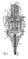
- the sensor arrangement has a temperature sensor 1 and a differential pressure sensor 2, which are arranged in a common sensor housing 3.
- the sensor housing 3 consists essentially of three injection molded parts, namely a front housing part 4 provided for incorporation into the pump housing and two housing halves 5 adjoining the rear, forming a cavity, which are of identical design.
- the front housing part 4 consists of a pin-shaped, tapered at its free end tapered projection 6, which has a substantially cylindrical shape and a flange-like part 7, which adjoins the back of the projection 6.
- the flange-like housing part 7 forms the mounting base of the entire sensor housing 3, with which this is fixed to the pump housing.
- the two housing halves 5 are placed on each other under inclusion of the components described below in more detail and by two bolts 8 firmly together connected. This rear housing part thus formed is then connected via two further bolts 9 with the front housing part 4, in particular the flange-like part 7.
- the sensor housing 3 thus formed is then inserted with its projection 6 in a corresponding receiving bore of the pump housing until the flange-like part 7 rests with the inclusion of a seal on a corresponding plane surface of the pump housing.
- the attachment is made with two screws through the holes provided in the flange 7 holes 10th
- the temperature sensor 1 is located near the front end of the projection 6 in a central inner recess 11 within the front housing part 4, which extends to near the free end of the projection 6. Adjacent to this central recess 11, two reversely directed outer recesses 12 are provided in the end face of the projection 6, which serve to reduce the wall thicknesses in this area.
- Adjacent to the central recess 11 are within the projection 6 two 180 ° relative to the longitudinal axis 13 of the projection 6 offset from each other arranged channels 14 which open into the wall passing pressure measuring 15, which are aligned with corresponding channel openings in the receiving bore of the pump housing to in this way to provide a communicating connection between the pressure port and suction port of the pump with the channels 14.
- the channels 14 are passed to the rear end of the front housing part 4, where they open in a frontal collar each a half of the housing 5, which is connected via a channel 16 with a space 17 which cuts through a form-fitting incorporated between the housing halves 5 bracket 18 is, which carries the differential pressure sensor 2. In this way, the differential pressure sensor 2 communicating with the pressure or suction chamber of the pump is connected.
- the channels 16 leading collar are each surrounded by an O-ring 19, which is sealingly clamped when screwing the front housing part 4 with the rear housing part between the end faces of these housing parts.
- the holder 18 is covered on both sides by a respective hat-shaped membrane 20, which merges into an O-ring-shaped outer bead. These membranes 20 seal the differential pressure sensor with respect to the pressure chambers 17, but transmit the pressure present there to the differential pressure sensor 2, since the free space formed between the membranes 20 and the differential pressure sensor 2 is filled with a pressure-transmitting gel.
- the holder 18 with the membranes 20 is incorporated in a form-fitting manner between the housing halves 5.
- the electrical leads 21 to the temperature sensor are, as indicated in Figure 1, led around the holder 18 and guided together with the rigidly led out of the holder 18 electrical connections of the differential pressure sensor 2 to a behind and transverse to the division plane of the housing halves 5 terminal board 22, the carries further electronic components and on which also from the sensor housing 3 is inserted from the rear side connecting line 23 is connected. About this line 23 all electrical line connections are formed to the outside.
- the lines guided therein can also be guided around the holder 18 without further sealing from the front housing part 4 into the rear housing part.
- the potentially pressurized areas to be encapsulated are adjacent.
- the terminal board 22 is positively incorporated between the housing halves 5, as well as the connection line 23, which is provided in this area with a known strain relief and kink protection element 24.
- the projection 6 has a sealing lip 25 which extends in the region of the cylindrical part approximately parallel to the longitudinal axis 13 on both sides and is guided transversely over the end face.
- This sealing lip 25 serves to seal the Druckmeßan say 15 relative to the cylinder bore in the pump housing.
- this sealing lip has an interruption 26, which forms a throttle point in conjunction with the corresponding receiving bore in the pump housing and provides a low volume, but targeted flow around the projection 6 to increase the accuracy of the temperature measurement.
- This interruption can possibly be replaced by a corresponding hole, or, if a flow around is not desired, also omitted.
Landscapes
- Physics & Mathematics (AREA)
- General Physics & Mathematics (AREA)
- Engineering & Computer Science (AREA)
- Chemical & Material Sciences (AREA)
- Analytical Chemistry (AREA)
- Automation & Control Theory (AREA)
- Fluid Mechanics (AREA)
- Combustion & Propulsion (AREA)
- Mechanical Engineering (AREA)
- General Engineering & Computer Science (AREA)
- Control Of Non-Positive-Displacement Pumps (AREA)
- Measuring Fluid Pressure (AREA)
- Structures Of Non-Positive Displacement Pumps (AREA)
Applications Claiming Priority (2)
| Application Number | Priority Date | Filing Date | Title |
|---|---|---|---|
| DE19700965A DE19700965C1 (de) | 1997-01-14 | 1997-01-14 | Sensoranordnung |
| EP97122654A EP0853232B1 (fr) | 1997-01-14 | 1997-12-22 | Agencement de capteur |
Related Parent Applications (2)
| Application Number | Title | Priority Date | Filing Date |
|---|---|---|---|
| EP97122654A Division EP0853232B1 (fr) | 1997-01-14 | 1997-12-22 | Agencement de capteur |
| EP97122654.3 Division | 1997-12-22 |
Publications (3)
| Publication Number | Publication Date |
|---|---|
| EP1835265A2 true EP1835265A2 (fr) | 2007-09-19 |
| EP1835265A3 EP1835265A3 (fr) | 2013-03-13 |
| EP1835265B1 EP1835265B1 (fr) | 2014-11-05 |
Family
ID=7817312
Family Applications (2)
| Application Number | Title | Priority Date | Filing Date |
|---|---|---|---|
| EP07010201.7A Expired - Lifetime EP1835265B1 (fr) | 1997-01-14 | 1997-12-22 | Dispositif de détection |
| EP97122654A Expired - Lifetime EP0853232B1 (fr) | 1997-01-14 | 1997-12-22 | Agencement de capteur |
Family Applications After (1)
| Application Number | Title | Priority Date | Filing Date |
|---|---|---|---|
| EP97122654A Expired - Lifetime EP0853232B1 (fr) | 1997-01-14 | 1997-12-22 | Agencement de capteur |
Country Status (3)
| Country | Link |
|---|---|
| US (1) | US5975842A (fr) |
| EP (2) | EP1835265B1 (fr) |
| DE (2) | DE19700965C1 (fr) |
Families Citing this family (18)
| Publication number | Priority date | Publication date | Assignee | Title |
|---|---|---|---|---|
| DE29619778U1 (de) * | 1996-11-15 | 1998-03-12 | Steinel Ag, Einsiedeln | Druck- und Temperatursensor |
| US20050086082A1 (en) * | 1999-01-21 | 2005-04-21 | Patient Care Technologies | Portable health assistant |
| DE10035458C2 (de) * | 1999-08-02 | 2002-10-24 | Wilo Gmbh | Kombi-Meßfühler |
| DE50015477D1 (de) * | 2000-02-15 | 2009-01-22 | Endress & Hauser Gmbh & Co Kg | Drucksensor |
| DE10007924A1 (de) * | 2000-02-21 | 2001-08-23 | Wilo Gmbh | Anschlußvorrichtung für eine Heizungspumpe |
| US6657217B2 (en) | 2001-04-10 | 2003-12-02 | York International Corporation | Probe for sensing movement in a compressor system |
| US20050109792A1 (en) * | 2002-06-17 | 2005-05-26 | Eltek S.P.A. | Method and device for detecting and checking the quality or properties of a mixture of fluids, in particular a food or domestic mixture |
| DE102005056762A1 (de) * | 2005-11-29 | 2007-05-31 | Robert Bosch Gmbh | Kombinierter Druck-Temperatursensor mit zentrischer Temperaturmessung |
| DE102005060674C5 (de) * | 2005-12-19 | 2020-02-27 | Asm Automation Sensorik Messtechnik Gmbh | Positionssensor in Stabbauweise sowie Verfahren zum Austausch |
| US7658227B2 (en) * | 2008-04-24 | 2010-02-09 | Baker Hughes Incorporated | System and method for sensing flow rate and specific gravity within a wellbore |
| DE102012204950A1 (de) | 2012-03-28 | 2013-10-02 | Robert Bosch Gmbh | Sensor zur Erfassung eines Drucks und einer Temperatur eines fluiden Mediums |
| US8858074B2 (en) * | 2012-07-16 | 2014-10-14 | United Technologies Corporation | Damped EGT probe |
| HUE030885T2 (en) * | 2013-04-26 | 2017-06-28 | Grieshaber Vega Kg | sensor Unit |
| CN104279168A (zh) * | 2014-09-12 | 2015-01-14 | 南通远东微特电机有限公司 | 一种新型的冷却泵 |
| ES2719602T3 (es) * | 2014-12-03 | 2019-07-11 | Grundfos Holding As | Conjunto sensor |
| CN107003158A (zh) * | 2014-12-03 | 2017-08-01 | 格兰富控股联合股份公司 | 传感器组件 |
| DE102021111975A1 (de) | 2021-05-07 | 2022-11-10 | Fte Automotive Gmbh | Flüssigkeitspumpe |
| DE102023208636A1 (de) * | 2023-09-07 | 2025-03-13 | Zf Friedrichshafen Ag | Gehäuse für eine Funktionseinrichtung eines Antriebsstrangs eines Fahrzeugs und Funktionseinrichtung |
Citations (2)
| Publication number | Priority date | Publication date | Assignee | Title |
|---|---|---|---|---|
| DE3923027A1 (de) | 1989-07-13 | 1991-01-17 | Oplaender Wilo Werk Gmbh | Vorrichtung zum regeln einer pumpe |
| FR2691802A1 (fr) | 1992-05-27 | 1993-12-03 | Controle Measure Regulation | Capteur mixte de pression et de température. |
Family Cites Families (21)
| Publication number | Priority date | Publication date | Assignee | Title |
|---|---|---|---|---|
| FR611255A (fr) * | 1926-09-24 | |||
| DE243107C (fr) * | ||||
| DE715975C (de) * | 1936-04-21 | 1942-01-10 | Ig Farbenindustrie Ag | Vorrichtung zur Einfuehrung von Thermoelementen in Hochdruckgefaesse fuer die Druckhydrierung von Kohlen und anderen Brennstoffen |
| US3439356A (en) * | 1965-06-14 | 1969-04-15 | North American Rockwell | Pressure-temperature sensor |
| US3808601A (en) * | 1972-06-28 | 1974-04-30 | Geophysical Res Corp | Short down-hole recording pressure or temperature gauge |
| CS175700B1 (fr) * | 1974-07-30 | 1977-05-31 | ||
| DE3111708A1 (de) * | 1981-03-25 | 1982-10-07 | Elac Ingenieurtechnik GmbH, 2300 Kiel | Elektrische messeinrichtung zur messung der temperatur und des druckes in einem fluessigkeitskreislauf von verbrennungsmotoren in mit bordcomputern ausgeuesteten fahrzeugen |
| DE3513749C1 (de) * | 1985-04-17 | 1986-09-04 | Hydrotechnik Gmbh | Sensor fuer fluidische Systeme |
| US5070732A (en) * | 1987-09-17 | 1991-12-10 | Square D Company | Modular sensor device |
| JPH0610640B2 (ja) * | 1988-01-27 | 1994-02-09 | 株式会社オリエンテック | 高温流体用の圧力・温度測定センサ |
| DE3823449A1 (de) * | 1988-07-11 | 1990-01-18 | Bosch Gmbh Robert | Messeinrichtung zur erfassung des drucks und der temperatur |
| DE3828207A1 (de) * | 1988-08-19 | 1990-02-22 | Oplaender Wilo Werk Gmbh | Diagnosestecker |
| DE3920185A1 (de) * | 1989-06-21 | 1991-01-10 | Oplaender Wilo Werk Gmbh | Kreiselpumpe oder luefter |
| BR9001636A (pt) * | 1990-04-06 | 1991-11-05 | Companhia Masa Vetco Comercio | Dispositivo integrado sensor-transdutor e sensor-transdutor de pressao |
| US5070706A (en) * | 1990-07-10 | 1991-12-10 | Sundstrand Corporation | Superheat sensor with single coupling to fluid line |
| US5199789A (en) * | 1990-11-19 | 1993-04-06 | Mauric Stanley J | Immersion well assembly |
| DE4121430C1 (fr) * | 1991-06-28 | 1992-11-05 | Grundfos International A/S, Bjerringbro, Dk | |
| DE4225879A1 (de) * | 1991-08-14 | 1993-02-18 | Volkswagen Ag | Messeinrichtung zur erfassung von druck und temperatur in einer druckgiessmaschine |
| US5199297A (en) * | 1991-10-04 | 1993-04-06 | Anheuser-Busch, Incorporated | Thin walled can temperature and pressure monitoring device and method |
| JP3111816B2 (ja) * | 1993-10-08 | 2000-11-27 | 株式会社日立製作所 | プロセス状態検出装置 |
| DE19544173C1 (de) * | 1995-11-14 | 1997-06-05 | Grundfos As | Gehäuse für eine Kreiselpumpe |
-
1997
- 1997-01-14 DE DE19700965A patent/DE19700965C1/de not_active Expired - Fee Related
- 1997-12-22 EP EP07010201.7A patent/EP1835265B1/fr not_active Expired - Lifetime
- 1997-12-22 DE DE59712865T patent/DE59712865D1/de not_active Expired - Lifetime
- 1997-12-22 EP EP97122654A patent/EP0853232B1/fr not_active Expired - Lifetime
-
1998
- 1998-01-14 US US09/007,113 patent/US5975842A/en not_active Expired - Lifetime
Patent Citations (2)
| Publication number | Priority date | Publication date | Assignee | Title |
|---|---|---|---|---|
| DE3923027A1 (de) | 1989-07-13 | 1991-01-17 | Oplaender Wilo Werk Gmbh | Vorrichtung zum regeln einer pumpe |
| FR2691802A1 (fr) | 1992-05-27 | 1993-12-03 | Controle Measure Regulation | Capteur mixte de pression et de température. |
Also Published As
| Publication number | Publication date |
|---|---|
| DE19700965C1 (de) | 1998-06-04 |
| EP0853232B1 (fr) | 2007-07-25 |
| EP1835265A3 (fr) | 2013-03-13 |
| EP0853232A2 (fr) | 1998-07-15 |
| US5975842A (en) | 1999-11-02 |
| EP1835265B1 (fr) | 2014-11-05 |
| DE59712865D1 (de) | 2007-09-06 |
| EP0853232A3 (fr) | 2001-09-12 |
Similar Documents
| Publication | Publication Date | Title |
|---|---|---|
| EP1835265B1 (fr) | Dispositif de détection | |
| DE10196145B3 (de) | Druckwandler mit verbessertem Isolatorsystem | |
| DE3629226C2 (de) | Proportionales elektrohydraulisches Drucksteuerventil | |
| DE60115543T2 (de) | Zusatzvakuumassistenzeinheit für Fahrzeugbremskraftverstärker | |
| DE69617253T2 (de) | Druckwandlereinheit mit nicht-kontaminierendem körper | |
| DE19517676B4 (de) | Drucksensor für eine Brennkraftmaschine mit einem Ansaugrohr | |
| DE102007009394A1 (de) | Motorpumpeneinheit | |
| BR9916380A (pt) | Aparelho de deposição de gotìculas | |
| EP1637741A1 (fr) | Pompe et son unité de contrôle refroidie par le liquide pompé | |
| DE102009010876A1 (de) | Motorkopfstruktur | |
| WO2001009513A1 (fr) | Collecteur de pompe hydraulique | |
| DE112013002976T5 (de) | Thermischer Durchflussmesser | |
| DE112013002966T5 (de) | Thermischer Durchflussmesser | |
| EP0774583B1 (fr) | Carter pour une pompe centrifuge | |
| DE10392824T5 (de) | Preiswerter kapazitiver in sich geschlossener Druckgeber mit Plattenbeschichtung, Teilchenfilter | |
| AT517820B1 (de) | Kühlbare Vorrichtung zur Messung von Durchflussvorgängen von Fluiden | |
| DE102005043346B4 (de) | Strömungsmittelsensor mit einem Niederdruck-Ablauf | |
| EP0918197B1 (fr) | Ensemble pour installation de chauffage compact | |
| DE4435511C1 (de) | Pumpenaggregat | |
| DE102022121493A1 (de) | Flüssigkeits-Pumpvorrichtung | |
| IT8967960A1 (it) | Collettore di carburante ad elevata pressione atto ad essere inserito tra una pompa di alimentazione del carburante ed almeno una valvola di iniezione del carburante azionata elettromagneticamente | |
| DE102016209150A1 (de) | Sensor zur Bestimmung wenigstens eines Parameters eines durch einen Messkanal strömenden fluiden Mediums | |
| EP3534133A1 (fr) | Capteur de pression | |
| DE102008032309B4 (de) | Sensoranordnung zur Messung des Zustands einer Flüssigkeit, insbesondere von Öl | |
| EP1334319A1 (fr) | Echangeur thermique pour systeme de chauffage supplementaire de vehicule |
Legal Events
| Date | Code | Title | Description |
|---|---|---|---|
| PUAI | Public reference made under article 153(3) epc to a published international application that has entered the european phase |
Free format text: ORIGINAL CODE: 0009012 |
|
| AC | Divisional application: reference to earlier application |
Ref document number: 0853232 Country of ref document: EP Kind code of ref document: P |
|
| AK | Designated contracting states |
Kind code of ref document: A2 Designated state(s): AT BE CH DE DK ES FI FR GB GR IE IT LI LU MC NL PT SE |
|
| AX | Request for extension of the european patent |
Extension state: AL LT LV MK RO SI |
|
| PUAL | Search report despatched |
Free format text: ORIGINAL CODE: 0009013 |
|
| AK | Designated contracting states |
Kind code of ref document: A3 Designated state(s): AT BE CH DE DK ES FI FR GB GR IE IT LI LU MC NL PT SE |
|
| AX | Request for extension of the european patent |
Extension state: AL LT LV MK RO SI |
|
| RIC1 | Information provided on ipc code assigned before grant |
Ipc: F04D 15/00 20060101ALI20130205BHEP Ipc: G01K 13/02 20060101ALI20130205BHEP Ipc: F04D 29/00 20060101ALI20130205BHEP Ipc: F04D 27/00 20060101ALI20130205BHEP Ipc: G01K 17/12 20060101ALI20130205BHEP Ipc: G01D 11/24 20060101AFI20130205BHEP Ipc: F04D 17/16 20060101ALI20130205BHEP Ipc: G01L 19/00 20060101ALI20130205BHEP Ipc: G05D 16/20 20060101ALI20130205BHEP Ipc: G01L 19/14 20060101ALI20130205BHEP |
|
| 17P | Request for examination filed |
Effective date: 20130911 |
|
| RBV | Designated contracting states (corrected) |
Designated state(s): AT BE CH DE DK ES FI FR GB GR IE IT LI LU MC NL PT SE |
|
| 17Q | First examination report despatched |
Effective date: 20131004 |
|
| AKX | Designation fees paid |
Designated state(s): AT BE CH DE DK ES FI FR GB GR IE IT LI LU MC NL PT SE |
|
| REG | Reference to a national code |
Ref country code: DE Ref legal event code: R079 Ref document number: 59713100 Country of ref document: DE Free format text: PREVIOUS MAIN CLASS: G01D0011240000 Ipc: G01L0019060000 |
|
| RIC1 | Information provided on ipc code assigned before grant |
Ipc: G01D 11/24 20060101ALI20140508BHEP Ipc: G05D 16/20 20060101ALI20140508BHEP Ipc: G01K 17/12 20060101ALI20140508BHEP Ipc: F04D 15/00 20060101ALI20140508BHEP Ipc: G01L 19/06 20060101AFI20140508BHEP Ipc: G01L 19/14 20060101ALI20140508BHEP Ipc: G01L 19/00 20060101ALI20140508BHEP Ipc: G01K 13/02 20060101ALI20140508BHEP |
|
| GRAP | Despatch of communication of intention to grant a patent |
Free format text: ORIGINAL CODE: EPIDOSNIGR1 |
|
| INTG | Intention to grant announced |
Effective date: 20140627 |
|
| GRAS | Grant fee paid |
Free format text: ORIGINAL CODE: EPIDOSNIGR3 |
|
| GRAA | (expected) grant |
Free format text: ORIGINAL CODE: 0009210 |
|
| AC | Divisional application: reference to earlier application |
Ref document number: 0853232 Country of ref document: EP Kind code of ref document: P |
|
| AK | Designated contracting states |
Kind code of ref document: B1 Designated state(s): AT BE CH DE DK ES FI FR GB GR IE IT LI LU MC NL PT SE |
|
| REG | Reference to a national code |
Ref country code: GB Ref legal event code: FG4D Free format text: NOT ENGLISH |
|
| REG | Reference to a national code |
Ref country code: CH Ref legal event code: EP |
|
| REG | Reference to a national code |
Ref country code: AT Ref legal event code: REF Ref document number: 694873 Country of ref document: AT Kind code of ref document: T Effective date: 20141115 |
|
| REG | Reference to a national code |
Ref country code: IE Ref legal event code: FG4D Free format text: LANGUAGE OF EP DOCUMENT: GERMAN |
|
| REG | Reference to a national code |
Ref country code: DE Ref legal event code: R096 Ref document number: 59713100 Country of ref document: DE Effective date: 20141218 |
|
| REG | Reference to a national code |
Ref country code: NL Ref legal event code: VDEP Effective date: 20141105 |
|
| PG25 | Lapsed in a contracting state [announced via postgrant information from national office to epo] |
Ref country code: NL Free format text: LAPSE BECAUSE OF FAILURE TO SUBMIT A TRANSLATION OF THE DESCRIPTION OR TO PAY THE FEE WITHIN THE PRESCRIBED TIME-LIMIT Effective date: 20141105 Ref country code: PT Free format text: LAPSE BECAUSE OF FAILURE TO SUBMIT A TRANSLATION OF THE DESCRIPTION OR TO PAY THE FEE WITHIN THE PRESCRIBED TIME-LIMIT Effective date: 20150305 Ref country code: FI Free format text: LAPSE BECAUSE OF FAILURE TO SUBMIT A TRANSLATION OF THE DESCRIPTION OR TO PAY THE FEE WITHIN THE PRESCRIBED TIME-LIMIT Effective date: 20141105 Ref country code: ES Free format text: LAPSE BECAUSE OF FAILURE TO SUBMIT A TRANSLATION OF THE DESCRIPTION OR TO PAY THE FEE WITHIN THE PRESCRIBED TIME-LIMIT Effective date: 20141105 |
|
| PG25 | Lapsed in a contracting state [announced via postgrant information from national office to epo] |
Ref country code: SE Free format text: LAPSE BECAUSE OF FAILURE TO SUBMIT A TRANSLATION OF THE DESCRIPTION OR TO PAY THE FEE WITHIN THE PRESCRIBED TIME-LIMIT Effective date: 20141105 Ref country code: GR Free format text: LAPSE BECAUSE OF FAILURE TO SUBMIT A TRANSLATION OF THE DESCRIPTION OR TO PAY THE FEE WITHIN THE PRESCRIBED TIME-LIMIT Effective date: 20150206 |
|
| PG25 | Lapsed in a contracting state [announced via postgrant information from national office to epo] |
Ref country code: BE Free format text: LAPSE BECAUSE OF NON-PAYMENT OF DUE FEES Effective date: 20141231 |
|
| PG25 | Lapsed in a contracting state [announced via postgrant information from national office to epo] |
Ref country code: DK Free format text: LAPSE BECAUSE OF FAILURE TO SUBMIT A TRANSLATION OF THE DESCRIPTION OR TO PAY THE FEE WITHIN THE PRESCRIBED TIME-LIMIT Effective date: 20141105 |
|
| REG | Reference to a national code |
Ref country code: CH Ref legal event code: PL |
|
| REG | Reference to a national code |
Ref country code: DE Ref legal event code: R097 Ref document number: 59713100 Country of ref document: DE |
|
| PG25 | Lapsed in a contracting state [announced via postgrant information from national office to epo] |
Ref country code: MC Free format text: LAPSE BECAUSE OF FAILURE TO SUBMIT A TRANSLATION OF THE DESCRIPTION OR TO PAY THE FEE WITHIN THE PRESCRIBED TIME-LIMIT Effective date: 20141105 |
|
| PLBE | No opposition filed within time limit |
Free format text: ORIGINAL CODE: 0009261 |
|
| STAA | Information on the status of an ep patent application or granted ep patent |
Free format text: STATUS: NO OPPOSITION FILED WITHIN TIME LIMIT |
|
| REG | Reference to a national code |
Ref country code: IE Ref legal event code: MM4A |
|
| REG | Reference to a national code |
Ref country code: FR Ref legal event code: ST Effective date: 20150831 |
|
| 26N | No opposition filed |
Effective date: 20150806 |
|
| GBPC | Gb: european patent ceased through non-payment of renewal fee |
Effective date: 20150205 |
|
| PG25 | Lapsed in a contracting state [announced via postgrant information from national office to epo] |
Ref country code: IE Free format text: LAPSE BECAUSE OF NON-PAYMENT OF DUE FEES Effective date: 20141222 Ref country code: LI Free format text: LAPSE BECAUSE OF NON-PAYMENT OF DUE FEES Effective date: 20141231 Ref country code: CH Free format text: LAPSE BECAUSE OF NON-PAYMENT OF DUE FEES Effective date: 20141231 |
|
| PG25 | Lapsed in a contracting state [announced via postgrant information from national office to epo] |
Ref country code: FR Free format text: LAPSE BECAUSE OF NON-PAYMENT OF DUE FEES Effective date: 20150105 |
|
| PG25 | Lapsed in a contracting state [announced via postgrant information from national office to epo] |
Ref country code: IT Free format text: LAPSE BECAUSE OF FAILURE TO SUBMIT A TRANSLATION OF THE DESCRIPTION OR TO PAY THE FEE WITHIN THE PRESCRIBED TIME-LIMIT Effective date: 20141105 |
|
| PG25 | Lapsed in a contracting state [announced via postgrant information from national office to epo] |
Ref country code: GB Free format text: LAPSE BECAUSE OF NON-PAYMENT OF DUE FEES Effective date: 20150205 |
|
| REG | Reference to a national code |
Ref country code: AT Ref legal event code: MM01 Ref document number: 694873 Country of ref document: AT Kind code of ref document: T Effective date: 20141222 |
|
| PG25 | Lapsed in a contracting state [announced via postgrant information from national office to epo] |
Ref country code: AT Free format text: LAPSE BECAUSE OF NON-PAYMENT OF DUE FEES Effective date: 20141222 |
|
| PG25 | Lapsed in a contracting state [announced via postgrant information from national office to epo] |
Ref country code: LU Free format text: LAPSE BECAUSE OF NON-PAYMENT OF DUE FEES Effective date: 20141222 |
|
| PGFP | Annual fee paid to national office [announced via postgrant information from national office to epo] |
Ref country code: DE Payment date: 20161229 Year of fee payment: 20 |
|
| REG | Reference to a national code |
Ref country code: DE Ref legal event code: R071 Ref document number: 59713100 Country of ref document: DE |