EP1835362B1 - Fixateur et appareil de formation d'images comportant le fixateur - Google Patents
Fixateur et appareil de formation d'images comportant le fixateur Download PDFInfo
- Publication number
- EP1835362B1 EP1835362B1 EP07103653A EP07103653A EP1835362B1 EP 1835362 B1 EP1835362 B1 EP 1835362B1 EP 07103653 A EP07103653 A EP 07103653A EP 07103653 A EP07103653 A EP 07103653A EP 1835362 B1 EP1835362 B1 EP 1835362B1
- Authority
- EP
- European Patent Office
- Prior art keywords
- fixer
- fixing
- fixing rotator
- holder
- layer
- Prior art date
- Legal status (The legal status is an assumption and is not a legal conclusion. Google has not performed a legal analysis and makes no representation as to the accuracy of the status listed.)
- Ceased
Links
- 238000010438 heat treatment Methods 0.000 claims description 70
- 230000006698 induction Effects 0.000 claims description 69
- 229910052751 metal Inorganic materials 0.000 claims description 24
- 239000002184 metal Substances 0.000 claims description 24
- 239000000758 substrate Substances 0.000 claims description 18
- 108091008695 photoreceptors Proteins 0.000 claims description 14
- 239000000463 material Substances 0.000 claims description 6
- 229910001220 stainless steel Inorganic materials 0.000 claims description 4
- 239000010935 stainless steel Substances 0.000 claims description 4
- 239000006260 foam Substances 0.000 claims description 2
- 239000004519 grease Substances 0.000 claims description 2
- 239000010410 layer Substances 0.000 description 93
- 230000003247 decreasing effect Effects 0.000 description 9
- 239000002344 surface layer Substances 0.000 description 6
- 230000015572 biosynthetic process Effects 0.000 description 4
- 238000004140 cleaning Methods 0.000 description 4
- 230000007246 mechanism Effects 0.000 description 4
- 238000010008 shearing Methods 0.000 description 4
- 239000004642 Polyimide Substances 0.000 description 3
- 210000002615 epidermis Anatomy 0.000 description 3
- 238000000034 method Methods 0.000 description 3
- 229920001721 polyimide Polymers 0.000 description 3
- RYGMFSIKBFXOCR-UHFFFAOYSA-N Copper Chemical compound [Cu] RYGMFSIKBFXOCR-UHFFFAOYSA-N 0.000 description 2
- 229910052802 copper Inorganic materials 0.000 description 2
- 239000010949 copper Substances 0.000 description 2
- 229910052736 halogen Inorganic materials 0.000 description 2
- 150000002367 halogens Chemical class 0.000 description 2
- BQCADISMDOOEFD-UHFFFAOYSA-N Silver Chemical compound [Ag] BQCADISMDOOEFD-UHFFFAOYSA-N 0.000 description 1
- 230000009471 action Effects 0.000 description 1
- 229910052782 aluminium Inorganic materials 0.000 description 1
- XAGFODPZIPBFFR-UHFFFAOYSA-N aluminium Chemical compound [Al] XAGFODPZIPBFFR-UHFFFAOYSA-N 0.000 description 1
- 210000000078 claw Anatomy 0.000 description 1
- 239000003086 colorant Substances 0.000 description 1
- 125000004122 cyclic group Chemical group 0.000 description 1
- 238000001514 detection method Methods 0.000 description 1
- 230000004907 flux Effects 0.000 description 1
- -1 for example Substances 0.000 description 1
- 239000002783 friction material Substances 0.000 description 1
- 230000004048 modification Effects 0.000 description 1
- 238000012986 modification Methods 0.000 description 1
- 230000035699 permeability Effects 0.000 description 1
- 238000007747 plating Methods 0.000 description 1
- 229920001296 polysiloxane Polymers 0.000 description 1
- 239000011347 resin Substances 0.000 description 1
- 229920005989 resin Polymers 0.000 description 1
- 229910052709 silver Inorganic materials 0.000 description 1
- 239000004332 silver Substances 0.000 description 1
- 230000001360 synchronised effect Effects 0.000 description 1
- 230000032258 transport Effects 0.000 description 1
Images





Classifications
-
- G—PHYSICS
- G03—PHOTOGRAPHY; CINEMATOGRAPHY; ANALOGOUS TECHNIQUES USING WAVES OTHER THAN OPTICAL WAVES; ELECTROGRAPHY; HOLOGRAPHY
- G03G—ELECTROGRAPHY; ELECTROPHOTOGRAPHY; MAGNETOGRAPHY
- G03G15/00—Apparatus for electrographic processes using a charge pattern
- G03G15/20—Apparatus for electrographic processes using a charge pattern for fixing, e.g. by using heat
- G03G15/2003—Apparatus for electrographic processes using a charge pattern for fixing, e.g. by using heat using heat
- G03G15/2014—Apparatus for electrographic processes using a charge pattern for fixing, e.g. by using heat using heat using contact heat
- G03G15/206—Structural details or chemical composition of the pressure elements and layers thereof
-
- G—PHYSICS
- G03—PHOTOGRAPHY; CINEMATOGRAPHY; ANALOGOUS TECHNIQUES USING WAVES OTHER THAN OPTICAL WAVES; ELECTROGRAPHY; HOLOGRAPHY
- G03G—ELECTROGRAPHY; ELECTROPHOTOGRAPHY; MAGNETOGRAPHY
- G03G2215/00—Apparatus for electrophotographic processes
- G03G2215/00135—Handling of parts of the apparatus
- G03G2215/00139—Belt
- G03G2215/00143—Meandering prevention
- G03G2215/00151—Meandering prevention using edge limitations
-
- G—PHYSICS
- G03—PHOTOGRAPHY; CINEMATOGRAPHY; ANALOGOUS TECHNIQUES USING WAVES OTHER THAN OPTICAL WAVES; ELECTROGRAPHY; HOLOGRAPHY
- G03G—ELECTROGRAPHY; ELECTROPHOTOGRAPHY; MAGNETOGRAPHY
- G03G2215/00—Apparatus for electrophotographic processes
- G03G2215/20—Details of the fixing device or porcess
Definitions
- the present invention relates to a fixer and an image forming apparatus including the fixer, and more particularly to a fixer and an electronographic image forming apparatus including the fixer.
- an electronographic image forming apparatus such as a copying machine, a printer, and a facsimile machine may include an image forming mechanism for forming an image, e.g., a toner image, on a recording medium such as a sheet or an overhead projector film (OHP film), and a fixer to fix the toner image on the recording medium.
- a recording medium such as a sheet or an overhead projector film (OHP film)
- OHP film overhead projector film
- An example of a fixer includes a fixing member, a heat source to heat the fixing member, and a pressurizer.
- the pressurizer is pressed to the fixing member to form a fixing nip therebetween.
- the toner image is fused and fixed with heat from the fixing member and pressure from the pressurizer onto the recording medium.
- the fixing member may be a roller in which a heat source is provided.
- the fixing member may be a belt wound around a roller having a heat source therein.
- heat from a halogen heater provided near the heating member may be used.
- the heat source of the above fixer may be turned off during waiting time to save energy.
- the heat source is turned on and the fixing member is heated to a fixing temperature during warm-up time (startup time).
- startup time warm-up time
- the fixing member desirably has a lower heat capacity.
- an induction heating fixer 101 includes a fixing roller 3, a pressing roller 4, and an induction coil 5 as illustrated in FIG. 1 .
- the fixing roller 3 includes a support shaft 1 in its center and a fixing rotator 2 wound around the support shaft 1.
- the pressing roller 4 includes a core metal 6 and a rubber layer 7 around the core metal 6. The pressing roller 4 is pressed against the fixing roller 3 and a nip n is formed between the two rollers.
- the induction coil 5 is provided around the fixing roller 3 in a non-contact manner.
- FIG. 2 illustrates edges of the fixing roller 3 and the pressing roller 4 in their width direction (axis direction).
- the support shaft 1 includes a core metal 1a and an elastic insulating layer 1b wound on the core metal 1a. With the elastic insulating layer 1b, the nip n may have a sufficient width for fixing.
- the fixing rotator 2 includes an induction heating layer 2a, an elastic layer 2b, and a release layer 2c from inside.
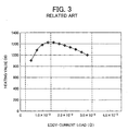
- the graph of FIG. 3 shows a relation between heating value and an eddy-current load at a frequency of 30 kHz.
- a thickness of the induction heating layer 2a at which the eddy-current load was optimum was checked by inductively heating the induction heating layer 2a that includes a material whose resistivity is lower at a frequency of around 30 kHz.
- the thickness of the induction heating layer 2a was less than a few dozen micro meters which was remarkably thinner than a thickness of a thin sleeve of a halogen heater that was a few hundreds micro meters.
- EP 1 569 047 A2 relates to a fixing apparatus.
- a fixing apparatus transports a recording medium carrying a developer image on it and heats the developer image to fix into the recording medium.
- a heat roller extends in a direction of its rotational axis and generates heat.
- An endless belt is loosely entrained on a belt guide.
- a pressurizing mechanism engages the endless belt from inside and urges the endless belt against the first rotating body. When the rotating body rotates, the endless belt and the first rotating body are driven in rotation in such a way that the recording medium is pulled in between the first rotating body and the endless belt.
- US 5,355,204 relates to an image fixing apparatus without crease of fixing film.
- An image fixing apparatus includes a heater; a movable film in contact with the heater and movable together with a recording material carrying an image to be fixed; a pressing rotatable member for urging the recording material and the film to the heater; and wherein the heater is substantially crowned in a direction perpendicular to a movement direction of the film, and the pressing rotatable member is substantially reversely crowned in the same direction.
- a heat roller type fixing device for an electrophotographic copier, printer, facsimile apparatus or similar electrostatic image recorder includes a hollow cylindrical fixing roller having a heating element thereinside and a hollow cylindrical pressing roller held in pressing contact with the fixing roller.
- a shaft is received in the pressing roller while two annular pressing members are mounted on the shaft through individual .bearings so as to urge the cylindrical inner periphery of the pressing roller.
- the pressing members are each movable on and along the shaft to any predetermined distance as measured from an end of the pressing roller.
- an image heating apparatus having a flexible sleeve.
- An object of the present invention is to provide an image heating apparatus having a flexible sleeve of an excellent durability.
- an image heating apparatus includes: a flexible sleeve; a driving roller contacting an external periphery surface of the sleeve and serving to rotate the sleeve; a sliding member contacting an internal periphery surface of the sleeve to form a nip portion in cooperation with the driving roller; and a restricting member for restricting a movement of the sleeve in a generatrix direction of the sleeve, wherein, within an edge face of the sleeve in a mounted state on the apparatus, equally bisected by an imaginary plane substantially parallel to a nip plane of the nip portion into a first area closer to the nip portion and a second area farther from the nip portion, the restricting
- a fixer configured to fix an image on an recording medium passing through a fixing nip includes a holder including an elastic layer, a fixing rotator including a heating layer, provided overlying the holder, and a pressurizer configured to pressurize the holder via the fixing rotator to form the fixing nip.
- a part of the pressurizer which forms the fixing nip has a length not less than a length of the heating layer in a width direction perpendicular to a conveyance direction of the recording medium.
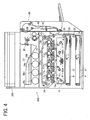
- FIG. 4 schematically illustrates an internal mechanism of the image forming apparatus 100 that may be a copier, a printer, a scanner, a facsimile machine, or a multi-function machine.
- a reading device 200 is provided over the image forming apparatus 100.
- the image forming apparatus 100 may be a tandem color printer including four image forming stations 10c, 10m, 10y, and 10b that are image forming mechanisms. Each of the image forming stations 10c, 10m, 10y, and 10b forms a cyan image, a magenta image, a yellow image, or a black image and includes one of photoreceptors 11c, 11m, 11y, and 11b.
- the image forming apparatus 100 may further include a writing device 14, an intermediate transfer member 15, and primary transferers 16c, 16m, 16y, and 16b. Each of the primary transferers 16c, 16m, 16y, and 16b may be provided at a position facing one of the photoreceptors 11c, 11m, 11y, and 11b across the intermediate transfer member 15.
- the image forming apparatus 100 may further include a plurality of feeding rollers 20, a plurality of sheet cassettes 21, a sheet conveyance path 23, a pair of registration rollers 24, a secondary transferer 25, a pair of ejection rollers 26, and a stacker 27.
- the image forming apparatus 100 may further include toner bottles 28c, 28m, 28y, and 28b, a secondary cleaning device 29, a fixer 300, a double-side printing unit 92, a switchback path 93, and a return path 94.
- the configuration and function thereof are described based on the image forming station 10c.
- the photoreceptor 11c is drum shaped and may rotate clockwise in FIG. 4 .
- the image forming station 10c may further include a charger 12c and an image developer 13c.
- the charger 12c applies bias voltage to the photoreceptor 11c to uniformly charge a surface thereof along with the rotation of the photoreceptor 11c.
- the reading device 200 may read image information from an original document and transmit the image information as a signal to the image forming apparatus 100.
- the image forming apparatus 100 is a printer, an image signal from a host may be received.
- the image forming apparatus 100 is a facsimile machine, a signal transmitted via telephone lines may be received.
- the writing device 14 as an irradiator that applies a laser light Lc based on the received signal to form an electrostatic latent image on the photoreceptor 11c.
- the image developer 13c may develop the electrostatic latent image with a cyan toner into a visible cyan image.
- magenta, yellow, and black images are formed on the photoreceptors 11m, 11y, and 11k in the image forming stations 10m, 10y, and 10b.
- the intermediate transfer member 15 may be an endless belt and may rotate counterclockwise in FIG. 4 while being in contact with the photoreceptors 11c, 11m, 11y, and 11b.
- the primary transferers 16c, 16m, 16y, and 16b may transfer the toner images on the photoreceptors 11c, 11m, 11y, and 11b in order from the cyan image onto the intermediate transfer member 15 as a primary transfer.
- the primary transferers 16c, 16m, 16y, and 16b may superimpose the toner images one another and form a full color image on the intermediate transfer member 15.
- the primary cleaning device 17c may clean and initialize the photoreceptor 11c.
- Each of the photoreceptor 11m, 11y, and 11b is similarly cleaned and initialized by a corresponding cleaning device.
- one of the feeding rollers 20 may be selected at a proper timing.
- the feeding roller 20 may rotate and send out a recording medium, such as a sheet P, from a corresponding sheet cassette 21.
- the sheet P is conveyed along the sheet conveyance path 23 and stopped when its leading edge is sandwiched between the pair of registration rollers 24.
- the registration rollers 24 may rotate and send the sheet P to a secondary transfer position in synchronized with the full color image on the intermediated transfer member 15.
- the secondary transferer 25 may transfer the full color image onto the sheet P.
- the sheet P is sent upward along the sheet conveyance path 23 to the fixer 300.
- the fixer 300 When the sheet P passes through the fixer 300, the full color image is fixed on the sheet P.
- the sheet P is ejected by the ejection rollers 26 and stacked on the stacker 27 above the image forming apparatus 100.
- the toner bottle 28c may supply the cyan toner to the image developer 13c.
- Each of the toner bottles 28m, 28y, and 28b similarly supplies the magenta, yellow, or black toner to a corresponding image developer.
- the secondary cleaning device 29 may clean and initialize the intermediate transfer member 15, for example, by removing any toner remaining thereon.
- the sheet P is sent to the double-side printing unit 92 by a switch claw (not shown) after the image (first image) is recorded on its first side and fixed by the fixer 300.
- the sheet P is reversed in the switchback path 93 and sent to the return path 94 so that a second side of the sheet P is turned up.
- the intermediate transfer member 15 On the intermediate transfer member 15, another image (second image) to be recorded on the second side is formed.
- the sheet P is sent to the secondary transferer 25 where the second image is transferred onto the second side of the sheet P.
- the sheet P is stacked on the stacker 27 by the pair of ejection rollers 26.
- the image forming apparatus 100 may arbitrarily form a monochrome or color image by selectively using at least one of the image forming stations 10c, 10m, 10y, and 10b according to the selected mode.
- the fixer 300 is described with reference to FIG. 5 .
- the fixer 300 may include a fixing roller 30, a pressing roller 40, an induction coil 50, an inverter circuit 52, a control circuit 53, and a thermistor 54.
- the fixing roller 30 includes a holder 32 and a fixing rotator 33 overlying the holder 32.
- the holder 32 and fixing rotator 33 may be unified to form a roller.
- the pressing roller 40 is a pressurizer and can be pressed to the fixing roller 30 to form a fixing nip n therebetween.
- the sheet P may pass the fixing nip n in a direction shown by arrow A in FIG. 5 .
- the induction coil 50 may partly cover the fixing roller 30 from a side opposite to the pressing roller 40.
- the pressing roller 40 may include a core metal 42 in its center and a rubber layer 43 overlying the core metal 42.
- the induction coil 50 may connect to the inverter circuit 52 to which the control circuit 53 may be connected.
- the thermistor 54 may detect a surface temperature of the fixing roller 30 and may input a detection result as a signal into the control circuit 53.
- the control circuit 53 may control the inverter circuit 52 based on the signal.
- the pressing roller 40 When the fixing roller 30 rotates, the pressing roller 40 may be driven to rotate.
- electric current is applied to the induction coil 50, a magnetic field of high frequency wave may be induced.
- the magnetic field may cause an induction current in the fixing rotator 33 and a surface layer of the fixing roller 30 may be heated with joule heating.
- image formation After warm-up of the fixer 300 is finished, image formation may be started. An image on the sheet P may be fixed when the sheet P passes through the fixing nip n.
- FIG. 6A illustrates layers in the holder 32.
- the holder 32 may include a core metal 34 and at least one elastic insulating layer 35 around the core metal 34.
- an elastic layer and an insulating layer are integrated in the elastic insulating layer 35.
- the elastic insulating layer 35 may separately include an elastic layer and an insulating layer.
- the elastic insulating layer 35 may include a foam, for example, an aerated silicone, and/or an elastic rubber.
- the elastic insulating layer 35 may have desirable rigidity to form a fixing nip having a desirable width.
- the elastic insulating layer 35 may have an insulating function, which may decrease heat capacity and start-up time of fixing.
- FIG. 6B illustrates layers in the fixing rotator 33.
- the fixing rotator 33 may include an induction heating layer 36 as a heating layer, an elastic body layer 37, and a release layer 38.
- the elastic body layer 37 may be provided on an outer surface of the induction heating layer 36.
- the release layer 38 may be formed on the elastic body layer 37.
- the induction heating layer 36 may include a metal. Volume resistivity of the metal may be not greater than 3.0 x 10 -8 ⁇ m, which may further decrease thickness of the induction heating layer 36 at which an eddy-current load of the fixing rotator 33 is optimum. Examples of the metal include silver, copper, and aluminum. Further, copper plating may be desirable.
- a desirable thickness of the induction heating layer 36 may be not greater than 100 ⁇ m.
- the elastic body layer 37 may have a thickness of 1 mm or less.
- the pressing roller 40 may be uniformly in contact with the release layer 38 of the fixing rotator 33 at the fixing nip n. Therefore, a decrease in heat conductivity may be prevented or reduced and uneven brightness of the transferred image on the sheet P may be prevented or reduced.
- FIG. 6C illustrates a fixing rotator 33a including a substrate 39 on its inner side as an exemplary embodiment.
- the substrate 39 may include a nonmagnetic stainless steel layer or a polyimide layer.
- the induction heating layer 36, the elastic body layer 37, and the release layer 38 may be formed on the substrate 39 in order.
- a desirable thickness of the substrate 39 plus the induction heating layer 36 may be not greater than 100 ⁇ m, so that flexural rigidity of the fixing rotator 33a is not excessively high. At this thickness, the fixing nip n may be effectively formed.
- the holder 32 having the elastic insulating layer 35 and the fixing rotator 33 having the induction heating member 36 may be separately formed.
- the fixing rotator 33 may be provided on the outer surface of the holder 32 and may be wholly or partially bonded to the holder 32 to form an integrated roller.
- the fixing roller 30 is manufactured as above, the fixing rotator 33 may not move to one side in its width direction on the holder 32 while rotating as described later. Therefore, damage to both edges of the fixing rotator 33 in the width direction may be prevented or reduced.
- FIG. 7 illustrates the edges of the fixing roller 30 and the pressing roller 40 in their width direction shown as arrow T (axis direction).
- the width direction is perpendicular to the sheet conveyance direction.
- a length of the pressing roller 40 at the fixing nip N in the width direction is shown as length L1.
- a Length of the elastic insulating layer 35 and the induction heating layer 36 is shown as length L2.
- the length L1 may be longer than the length L2 as in FIG. 7 .
- the elastic repulsion in an entire width of the induction heating layer 36 may be received by the pressing roller 40.
- the length L1 may be substantially equal to the length L2, although the length L1 is longer than the length L2 in FIG. 7 .
- the induction current is induced at an induction coil 50 side of the induction heating layer 36 in the fixing rotator 33. Accordingly, a surface layer of the fixing roller 30 may be heated with joule heating.
- the thickness of the induction heating layer 36 at which an eddy-current load of the fixing rotator 33 is optimum may be decreased and the heat capacity of the fixing rotator 33 may be decreased. Further, enough of a fixing nip N may be formed and less shearing force may occur in the induction heating layer 36, which may prevent or reduce damage of both edges of the fixing rotator 33 in the width direction shown as arrow T.
- FIG. 8 illustrates a fixer 300a as an exemplary embodiment to be installed in the image forming apparatus 100.
- the fixer 300 may include a fixing part 30a, a pressing roller 40a, an induction coil 50, an inverter circuit 52, a control circuit 53, and a thermistor 54.
- the fixing part 30a may include a roller-shaped holder 32, a fixing rotator 33b, a sleeve-shaped roller 60, and a tension roller 61.
- the fixing rotator 33b may be a flexible endless belt.
- the holder 32 and the fixing rotator 33b may be separately formed.
- the holder 32, the roller 60, and the tension roller 61 may serve as a plurality of supporters around which the fixing rotator 33b is stretched.
- the tension roller 61 may press the fixing rotator 33b from its inner surface so that the fixing rotator 33b is in tension.
- the holder 32 may include a core metal 34 and an elastic insulating layer 35 wound around the core metal 34, similarly to the fixing roller 30 illustrated in FIG. 5 .
- the pressing roller 40a may be pressed to the holder 32 via the fixing rotator 33b to form a fixing nip N between the pressing roller 40a and the fixing rotator 33b.
- the sheet P may pass the fixing nip N in a direction shown arrow A.
- the induction coil 50 may cover about a half of the roller 60 via the fixing rotator 33b.
- the induction coil 50 may connect to the inverter circuit 52 to which the control circuit 53 may be connected.
- the thermistor 54 may send a signal to the control circuit 53.
- the pressing roller 40a may include a core metal 42 and a rubber layer 43 around the core metal 42 similarly to the pressing roller 40 illustrated in FIG. 5 .
- the pressing roller 40a may further include a heater 44 therein. With the heater 44, the start-up time of fixing may be shortened. Since power consumption may be increased due to the heater 44, the heater 44 may not be necessary when power-saving is emphasized.
- the fixing rotator 33b When the holder 32 rotates and the roller 60 and the tension roller 61 are driven to rotate, the fixing rotator 33b may be rotated.
- the pressing roller 40a may be similarly driven to rotate.
- electric current is applied to the induction coil 50, a magnetic field of high frequency waves may be induced.
- the magnetic field may cause induction current in the fixing rotator 33b. Accordingly, a surface layer of the fixing rotator 33b may be heated with joule heating.
- image formation After warm-up of the fixer 300a is finished, image formation may be started. An image on the sheet P may be fixed when the sheet P passes through the fixing nip N.
- FIG. 9 illustrates edges of the holder 32, the fixing rotator 33b, and the pressing roller 40a in their width direction (axis direction) shown as arrow T.
- the width direction is perpendicular to the sheet conveyance direction.
- the fixing rotator 33b may include a substrate 39 on its inner side.
- an induction heating layer 36, an elastic body layer 37, and a release layer 38 may be formed in order, similarly to the fixing rotator 33a of FIG. 6C .
- the substrate 39 may include a nonmagnetic stainless steel layer having a higher modulus of direct elasticity (Young's modulus) and may have a thickness of 100 ⁇ m or less.
- the substrate 39 may include a polyimide having a thickness of 300 ⁇ m or less.
- a length of the pressing roller 40a at the fixing nip N in the direction of arrow T is shown as length L1.
- a length of the elastic insulating layer 35 and the induction heating layer 36 is shown as length L2.
- the length L1 may be longer than the length L2.
- the pressing roller 40a may receive the elastic repulsion in an entire width of the induction heating layer 36.
- the length L1 may be substantially equal to the length L2, although the length L1 is longer than the length L2 in FIG. 9 .
- the induction current is induced at an induction coil 50 side of the induction heating layer 36 in the fixing rotator 33b and a surface layer of the fixing rotator 33b may be heated with joule heating.
- the thickness of the induction heating layer 36 at which an eddy-current load of the fixing rotator 33b is optimum may be decreased and the heat capacity of the fixing rotator 33b may be decreased. Further, enough of a fixing nip N may be formed and less shearing force may occur in the induction heating layer 36, which may prevent or reduce damage to both edges of the fixing rotator 33b in the width direction (arrow T in FIG. 9 ).
- the supporters e.g. the holder 32, the roller 60, and the tension roller 61
- the supporters are rollers in FIG. 8 , as an exemplary embodiment.
- the supporters may be rollers, pads, or a combination thereof.
- the rotation of the holder 32 may cause the fixing rotator 33b to rotate
- another roller-shaped member around which the fixing rotator 33b is stretched may cause the fixing rotator 33b to rotate.
- the pressing roller 40a may cause the fixing rotator 33b to rotate.
- a pad-shaped pressurizer may be used.
- FIG. 10 illustrates a fixer 300b as an exemplary embodiment.
- the fixer 300b may include a fixing part 30b, a pressing roller 40, and an induction coil 50.
- the fixing part 30b may include a holder 32a and a fixing rotator 33c that are separately formed.
- the holder 32a may be a pad.
- the fixing rotator 33c may be a flexible, endless sleeve.
- the fixing rotator 33c may be stretched around the holder 32a.
- the holder 32a may include a substrate 34a and an elastic insulating layer 35 on the substrate 34a.
- the pressing roller 40 may be pressed to the holder 32a via the fixing rotator 33c to form a fixing nip N between the pressing roller 40 and the fixing rotator 33c.
- the sheet P may pass the fixing nip N in a direction shown an arrow in FIG. 10 .
- the induction coil 50 may cover a part of the fixing rotator 33c.
- the pressing roller 40 may include a core metal 42 and a rubber layer 43 around the core metal 42.
- the induction coil 50 may connect to an inverter circuit to which a control circuit may be connected, similarly to the fixer 300 in FIG. 5 .
- a thermistor may send a signal to the control circuit.
- the fixing rotator 33c When the pressing roller 40 rotates, the fixing rotator 33c may be rotated. When electric current is applied to the induction coil 50, a magnetic field of high frequency wave may be induced. The magnetic field may cause an induction current in the fixing rotator 33c. Accordingly, a surface layer of the fixing rotator 33c may be heated with joule heating. After warm-up of the fixer 300b is finished, image formation may be started. An image on the sheet P may be fixed when the sheet P passes through the fixing nip N.
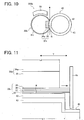
- FIG. 11 illustrates edges of the holder 32a, the fixing rotator 33c, and the pressing roller 40 in their width direction (axis direction) shown as arrow T.
- the width direction is perpendicular to the sheet conveyance direction.
- the fixer 300b may further include a pair of side plates 65 to cover the edges of the holder 32a, the fixing rotator 33c, and the pressing roller 40 in their width direction.
- the sleeve-shaped fixing rotator 33c may include a substrate 39, an induction heating layer 36, an elastic body layer 37, and a release layer 38, similarly to the fixing rotator 33a of FIG. 6C .
- the substrate 39 may include a nonmagnetic stainless steel layer having a higher modulus of direct elasticity and may have a thickness of 100 ⁇ m or less.
- the substrate 39 may include a polyimide having a thickness of 300 ⁇ m or less. It is desirable to include a low friction material, for example, oil or grease, between the holder 32a and the fixing rotator 33c.
- a length of the pressing roller 40 at the fixing nip N in the direction of arrow T is shown as length L1.
- FIG. 11 illustrates a state in which the fixing rotator 33c rotates to one side and the edge thereof protrudes from an edge of the holder 32a in the direction shown as arrow T
- the induction heating layer 36 has a similar length to a length of the elastic insulating layer 35 shown as length L2.
- the length L1 may be substantially equal to or longer than the length L2.
- the induction current is induced at an induction coil 50 side of the induction heating layer 36 in the fixing rotator 33c and a surface layer of the fixing rotator 33c may be heated with joule heating.
- the thickness of the induction heating layer 36 at which an eddy-current load of the fixing rotator 33c is optimum may be decreased and the heat capacity of the fixing rotator 33c may be decreased. Further, enough of a fixing nip N may be formed and less shearing force may occur in the induction heating layer 36. Accordingly, mechanical strength of the edges of the fixing rotator 33c in the width direction (arrow T) may be enhanced, which may prevent or reduce damage to both edges of the fixing rotator 33c in the width direction.
- the fixing rotator 33c stretched around the holder 32a is rotated.
- the holder 32a may be roller-shaped and fixing rotator 33c may be rotated by rotation of the holder 32a.
- the shape of the pressurizer may be a pad, and is not limited to a roller.
- the fixing rotator When the fixing rotator is an endless belt as illustrated in FIG. 8 , or a sleeve, as illustrated in FIG. 10 , and is stretched around the holder that is formed separately from the fixing rotator, the fixing rotator may move to one side in the width direction on the holder while rotating.
- FIG. 13 illustrates a fixer 300c as an exemplary embodiment.
- the fixer 300c may include a holder 32a, a fixing rotator 33c, a pressing roller 40, and a pair of sidewalls 65.
- the fixer 300c may have a similar structure to the fixer 300b illustrated in FIGs. 10 and 11 , except for a pair of stoppers 68 provided on the edges of the fixing rotator 33c.
- the fixing rotator 33c may be an endless, flexible material and may be stretched around the holder 32a that may be a pad or a roller. As shown in FIG. 13 , a length of the holder 32a may be shorter than a length of the fixing rotator 33c in the direction of arrow T to make space to attach the stoppers 68 on both edges of the fixing rotator 33c.
- the stoppers 68 may include a high-temperature resin. When the fixing rotator 33c moves to one side in the direction of arrow T on the holder 32a while rotating, one of the stoppers 68 contacts an edge surface of the holder 32a. The stopper 68 may prevent the fixing rotator 33c from moving further to the side and hitting the sidewall 65. Therefore, the damage on the edges of the fixing rotator 33c may be prevented.
Landscapes
- Physics & Mathematics (AREA)
- General Physics & Mathematics (AREA)
- Fixing For Electrophotography (AREA)
Claims (15)
- Dispositif de fixage configuré pour fixer une image sur un support d'enregistrement (P) passant à travers un pincement de fixage (n ; N), le dispositif de fixage (300 ; 300a ; 300b ; 300c) comprenant :un support (32 ; 32a) comprenant un noyau métallique (34) et une couche élastique (35) ;un élément rotatif de fixage (33 ; 33a ; 33b ; 33c) comprenant une couche chauffante (36), prévue de manière à recouvrir le support (32 ; 32a) ; etun élément de pression (40 ; 40a) comprenant un noyau métallique (42) et une couche de caoutchouc (43) recouvrant le noyau métallique (42), dans lequel l'élément de pression (40 ; 40a) est configuré pour presser le support (32 ; 32a), par l'intermédiaire de l'élément rotatif de fixage (33 ; 33a ; 33b ; 33c), pour former le pincement de fixage (n ; N),dans lequel une partie de l'élément de pression (40 ; 40a), qui forme le pincement de fixage (n ; N), a une première longueur (L1) qui est plus grande qu'une deuxième longueur (L2) de la couche chauffante (36) dans une direction de largeur perpendiculaire à une direction de transport du support d'enregistrement (P), caractérisé en ce que le dispositif de fixage (300 ; 300a ; 300b ; 300c) comprend en outre une bobine d'induction (50) configurée pour couvrir une partie de l'élément rotatif de fixage (33 ; 33a ; 33b ; 33c), dans lequel l'élément rotatif de fixage (33 ; 33a ; 33b ; 33c) comprend en outre un substrat (39) sur son côté interne, et la couche chauffante (36) est formée sur le substrat (39), dans lequel le substrat (39) comprend un acier inoxydable non magnétique et a une épaisseur inférieure ou égale à 100 µm, dans lequel la couche élastique (35) comprend une mousse.
- Dispositif de fixage selon la revendication 1, dans lequel la couche chauffante (36) comprend un métal ayant une résistivité volumique inférieure ou égale à 3,0 x 10⁻⁸ Ωm.
- Dispositif de fixage selon la revendication 1, dans lequel la couche chauffante (36) a une épaisseur inférieure ou égale à 100 µm.
- Dispositif de fixage selon la revendication 1, dans lequel la couche chauffante (36) a une épaisseur inférieure ou égale à 100 µm comprenant le substrat (39).
- Dispositif de fixage selon la revendication 1, dans lequel la couche élastique (35) comprend un caoutchouc élastique.
- Dispositif de fixage selon la revendication 1, dans lequel l'élément rotatif de fixage (33 ; 33a ; 33b ; 33c) comprend en outre :une couche de corps élastique (37) située de manière à recouvrir la couche chauffante (36) et ayant une épaisseur inférieure ou égale à 1 mm ; etune couche anti-adhésive (38) située de manière à recouvrir la couche de corps élastique (37).
- Dispositif de fixage selon la revendication 1, dans lequel le support (32 ; 32a) et l'élément rotatif de fixage (33 ; 33a ; 33b ; 33c) sont unifiés en la forme d'un rouleau pour former un rouleau de fixage (30).
- Dispositif de fixage selon la revendication 1, dans lequel l'élément rotatif de fixage (33 ; 33a ; 33b ; 33c) est lié au support (32 ; 32a).
- Dispositif de fixage selon la revendication 1, dans lequel le support (32 ; 32a) est un rouleau ou un tampon, et l'élément rotatif de fixage (33 ; 33a ; 33b ; 33c) est constitué d'un matériau souple sans fin étendu autour du support (32 ; 32a).
- Dispositif de fixage selon la revendication 9, comprenant en outre :une pluralité d'éléments de support (32, 60, 61),dans lequel l'élément rotatif de fixage (33 ; 33a ; 33b ; 33c) a la forme d'une courroie sans fin étendue autour de la pluralité d'éléments de support (32, 60, 61) comprenant le support (32 ; 32a).
- Dispositif de fixage selon la revendication 10, dans lequel les éléments de support (32, 60, 61) sont des rouleaux, des tampons, ou une combinaison de ceux-ci.
- Dispositif de fixage selon la revendication 9, dans lequel l'élément rotatif de fixage (33 ; 33a ; 33b ; 33c) a la forme d'une gaine sans fin étendue autour du support (32 ; 32a).
- Dispositif de fixage selon la revendication 9, comprenant en outre :de l'huile ou de la graisse située entre l'élément rotatif de fixage (33 ; 33a ; 33b ; 33c) et le support (32 ; 32a), dans lequel l'élément rotatif de fixage (33 ; 33a ; 33b ; 33c) est configuré pour tourner du fait de la rotation de l'élément de pression (40 ; 40a).
- Dispositif de fixage selon la revendication 9, comprenant en outre :deux butées (68) sur les deux bords de l'élément rotatif de fixage (33 ; 33a ; 33b ; 33c) dans la direction de largeur,dans lequel chacune des butées (68) est configurée pour empêcher la rotation de l'élément rotatif de fixage (33 ; 33a ; 33b ; 33c) vers un côté tout en étant en contact avec une surface de bord du support (32 ; 32a).
- Appareil de formation d'image, comprenant :un photorécepteur (11c, 11m, 11y, 11b) ;un chargeur (12c, 12m, 12y, 12b) configuré pour charger le photorécepteur (11c, 11m, 11y, 11b) ;un dispositif d'irradiation (14) configuré pour irradier le photorécepteur (11c, 11m, 11y, 11b) pour former une image latente électrostatique sur celui-ci ;un dispositif de développement d'image (13c, 13m, 13y, 13b) configuré pour développer l'image latente électrostatique avec un toner pour former une image de toner ;un dispositif de transfert (25) configuré pour transférer l'image de toner sur un support d'enregistrement (P) ; etun dispositif de fixage (300 ; 300a ; 300b ; 300c) selon l'une quelconque des revendications 1 à 14 configuré pour fixer l'image de toner sur le support d'enregistrement (P).
Applications Claiming Priority (2)
| Application Number | Priority Date | Filing Date | Title |
|---|---|---|---|
| JP2006067386 | 2006-03-13 | ||
| JP2006283310A JP2007279669A (ja) | 2006-03-13 | 2006-10-18 | 定着装置、画像形成装置、および定着装置の定着ニップ形成方法 |
Publications (2)
| Publication Number | Publication Date |
|---|---|
| EP1835362A1 EP1835362A1 (fr) | 2007-09-19 |
| EP1835362B1 true EP1835362B1 (fr) | 2011-05-11 |
Family
ID=38016484
Family Applications (1)
| Application Number | Title | Priority Date | Filing Date |
|---|---|---|---|
| EP07103653A Ceased EP1835362B1 (fr) | 2006-03-13 | 2007-03-07 | Fixateur et appareil de formation d'images comportant le fixateur |
Country Status (3)
| Country | Link |
|---|---|
| US (1) | US7817952B2 (fr) |
| EP (1) | EP1835362B1 (fr) |
| JP (1) | JP2007279669A (fr) |
Families Citing this family (64)
| Publication number | Priority date | Publication date | Assignee | Title |
|---|---|---|---|---|
| JP5065871B2 (ja) * | 2007-12-11 | 2012-11-07 | 株式会社リコー | 定着装置及び画像形成装置 |
| US20090232568A1 (en) * | 2008-03-17 | 2009-09-17 | Kabushiki Kaisha Toshiba | Fixing apparatus and developer fixing method for the fixing apparatus |
| JP5286869B2 (ja) * | 2008-03-25 | 2013-09-11 | 株式会社リコー | 定着装置、画像形成装置 |
| JP5360686B2 (ja) * | 2009-05-27 | 2013-12-04 | 株式会社リコー | 定着装置及び画像形成装置 |
| US8213849B2 (en) * | 2009-07-20 | 2012-07-03 | Xerox Corporation | Inductively heated carbon nanotube fuser |
| JP5418068B2 (ja) * | 2009-08-26 | 2014-02-19 | 株式会社リコー | 定着装置および画像形成装置 |
| JP5375469B2 (ja) * | 2009-09-14 | 2013-12-25 | 株式会社リコー | 定着装置及び画像形成装置 |
| JP2011081338A (ja) * | 2009-09-14 | 2011-04-21 | Ricoh Co Ltd | 定着装置 |
| JP5581634B2 (ja) * | 2009-09-15 | 2014-09-03 | 株式会社リコー | 定着装置および画像形成装置 |
| JP5333194B2 (ja) * | 2009-12-22 | 2013-11-06 | 株式会社リコー | 定着装置及び画像形成装置 |
| US8488981B2 (en) * | 2010-03-11 | 2013-07-16 | Ricoh Company, Ltd. | Fixing device and image forming apparatus using the same |
| JP2011191607A (ja) | 2010-03-16 | 2011-09-29 | Ricoh Co Ltd | 定着装置及び画像形成装置 |
| JP5560791B2 (ja) * | 2010-03-16 | 2014-07-30 | 株式会社リコー | 熱定着装置及び画像形成装置 |
| JP5515898B2 (ja) * | 2010-03-17 | 2014-06-11 | 株式会社リコー | 定着装置及び画像形成装置 |
| JP2011197154A (ja) | 2010-03-17 | 2011-10-06 | Ricoh Co Ltd | 定着装置、定着方法、画像形成装置及び画像形成方法 |
| JP5510727B2 (ja) | 2010-06-21 | 2014-06-04 | 株式会社リコー | 定着装置及び画像形成装置 |
| JP5617431B2 (ja) | 2010-08-19 | 2014-11-05 | 株式会社リコー | 定着装置及び画像形成装置 |
| JP5593973B2 (ja) | 2010-08-30 | 2014-09-24 | 株式会社リコー | 定着装置及び画像形成装置 |
| JP5610148B2 (ja) | 2010-10-18 | 2014-10-22 | 株式会社リコー | 画像形成装置 |
| JP2012088491A (ja) | 2010-10-19 | 2012-05-10 | Ricoh Co Ltd | 定着ローラ、定着装置及び画像形成装置 |
| JP5492734B2 (ja) * | 2010-10-25 | 2014-05-14 | 京セラドキュメントソリューションズ株式会社 | 定着装置及び画像形成装置 |
| JP5707867B2 (ja) | 2010-11-01 | 2015-04-30 | 株式会社リコー | 定着装置および画像形成装置 |
| JP2012118481A (ja) | 2010-11-10 | 2012-06-21 | Ricoh Co Ltd | 定着装置、画像形成装置、及び定着装置の制御方法 |
| JP5625924B2 (ja) | 2011-01-11 | 2014-11-19 | 株式会社リコー | 電磁誘導加熱方式定着装置と画像形成装置 |
| JP2012168403A (ja) | 2011-02-15 | 2012-09-06 | Ricoh Co Ltd | 定着装置及び画像形成装置 |
| JP5796303B2 (ja) | 2011-02-16 | 2015-10-21 | 株式会社リコー | 定着装置及び画像形成装置 |
| JP5760505B2 (ja) | 2011-02-25 | 2015-08-12 | 株式会社リコー | 定着装置及び画像形成装置 |
| US8855542B2 (en) * | 2011-08-26 | 2014-10-07 | Kabushiki Kaisha Toshiba | Fuser, image forming apparatus, and image forming method |
| JP5737629B2 (ja) | 2011-12-26 | 2015-06-17 | 株式会社リコー | 定着装置及び画像形成装置 |
| JP6136221B2 (ja) | 2011-12-27 | 2017-05-31 | 株式会社リコー | 定着装置、及び、画像形成装置 |
| JP6136220B2 (ja) | 2011-12-27 | 2017-05-31 | 株式会社リコー | 定着装置、及び、画像形成装置 |
| JP5796711B2 (ja) | 2011-12-28 | 2015-10-21 | 株式会社リコー | 定着装置及び画像形成装置 |
| JP5904325B2 (ja) | 2011-12-28 | 2016-04-13 | 株式会社リコー | 定着装置及び画像形成装置 |
| US9063480B2 (en) | 2011-12-28 | 2015-06-23 | Ricoh Company, Limited | Fixing device, image forming device, and separating member |
| JP5928783B2 (ja) | 2012-01-11 | 2016-06-01 | 株式会社リコー | 定着装置および画像形成装置 |
| JP5761524B2 (ja) | 2012-01-13 | 2015-08-12 | 株式会社リコー | 定着装置及び画像形成装置 |
| JP5737520B2 (ja) | 2012-01-13 | 2015-06-17 | 株式会社リコー | 定着装置及び画像形成装置 |
| JP5970828B2 (ja) | 2012-01-19 | 2016-08-17 | 株式会社リコー | 分離部材、定着装置、及び画像形成装置 |
| JP6024108B2 (ja) | 2012-01-19 | 2016-11-09 | 株式会社リコー | 定着装置及び画像形成装置 |
| JP6333511B6 (ja) | 2012-01-23 | 2023-11-08 | 株式会社リコー | 定着装置及び画像形成装置 |
| JP5967468B2 (ja) | 2012-01-24 | 2016-08-10 | 株式会社リコー | 定着装置、及び、画像形成装置 |
| JP5943231B2 (ja) | 2012-01-26 | 2016-07-05 | 株式会社リコー | 定着装置、及び、画像形成装置 |
| JP6035668B2 (ja) | 2012-01-27 | 2016-11-30 | 株式会社リコー | 定着装置、及び、画像形成装置 |
| JP6052598B2 (ja) | 2012-01-30 | 2016-12-27 | 株式会社リコー | 定着装置および画像形成装置 |
| JP6051741B2 (ja) | 2012-01-31 | 2016-12-27 | 株式会社リコー | 定着装置および画像形成装置 |
| JP5963105B2 (ja) | 2012-02-02 | 2016-08-03 | 株式会社リコー | 定着装置及び画像形成装置 |
| JP5896281B2 (ja) | 2012-02-09 | 2016-03-30 | 株式会社リコー | 画像形成装置 |
| JP6003619B2 (ja) | 2012-02-09 | 2016-10-05 | 株式会社リコー | 定着装置及び画像形成装置 |
| JP6019779B2 (ja) | 2012-02-09 | 2016-11-02 | 株式会社リコー | 定着装置及び画像形成装置 |
| US9026024B2 (en) | 2012-02-09 | 2015-05-05 | Ricoh Company, Ltd. | Fixing device capable of minimizing damage of endless rotary body and image forming apparatus incorporating same |
| JP6201312B2 (ja) | 2012-02-09 | 2017-09-27 | 株式会社リコー | 画像形成装置 |
| JP6032525B2 (ja) | 2012-02-09 | 2016-11-30 | 株式会社リコー | 画像形成装置 |
| JP6209311B2 (ja) | 2012-02-09 | 2017-10-04 | 株式会社リコー | 定着装置及び画像形成装置 |
| JP6135051B2 (ja) | 2012-02-09 | 2017-05-31 | 株式会社リコー | 定着装置及び画像形成装置 |
| JP5850326B2 (ja) | 2012-02-09 | 2016-02-03 | 株式会社リコー | 定着装置および画像形成装置 |
| JP5948923B2 (ja) | 2012-02-09 | 2016-07-06 | 株式会社リコー | 定着装置及び画像形成装置 |
| JP6103679B2 (ja) | 2012-02-09 | 2017-03-29 | 株式会社リコー | 定着装置及び画像形成装置 |
| JP5995132B2 (ja) | 2012-02-09 | 2016-09-21 | 株式会社リコー | 定着装置及び画像形成装置 |
| JP2013164463A (ja) | 2012-02-09 | 2013-08-22 | Ricoh Co Ltd | 定着装置及び画像形成装置 |
| JP6423994B2 (ja) | 2012-02-09 | 2018-11-14 | 株式会社リコー | 定着装置及び画像形成装置 |
| JP6019785B2 (ja) | 2012-02-09 | 2016-11-02 | 株式会社リコー | 定着装置及び画像形成装置 |
| JP2013195857A (ja) | 2012-03-22 | 2013-09-30 | Ricoh Co Ltd | 定着装置、及び、画像形成装置 |
| JP5950152B2 (ja) | 2012-03-22 | 2016-07-13 | 株式会社リコー | 定着装置、及び、画像形成装置 |
| JP6016071B2 (ja) | 2012-05-18 | 2016-10-26 | 株式会社リコー | 定着装置及び画像形成装置 |
Family Cites Families (23)
| Publication number | Priority date | Publication date | Assignee | Title |
|---|---|---|---|---|
| US4942434A (en) * | 1987-12-11 | 1990-07-17 | Ricoh Company, Ltd. | Fixed roller for an electrostatic image recorder |
| JPH03233586A (ja) * | 1990-02-09 | 1991-10-17 | Canon Inc | 定着装置 |
| JPH0816007A (ja) | 1994-06-28 | 1996-01-19 | Canon Inc | 加熱装置および画像形成装置 |
| JP3350315B2 (ja) | 1995-09-09 | 2002-11-25 | 株式会社リコー | 定着装置 |
| JPH09218601A (ja) | 1996-02-14 | 1997-08-19 | Minolta Co Ltd | ベルト定着装置 |
| JP2002006649A (ja) * | 2000-06-19 | 2002-01-11 | Sharp Corp | 画像形成装置 |
| JP3824476B2 (ja) * | 2000-09-12 | 2006-09-20 | シャープ株式会社 | 加熱装置および画像形成装置 |
| JP2003017221A (ja) | 2001-07-03 | 2003-01-17 | Ricoh Co Ltd | 加熱装置及び画像形成装置 |
| JP2004205838A (ja) | 2002-12-25 | 2004-07-22 | Matsushita Electric Ind Co Ltd | 像加熱装置および画像形成装置 |
| JP2004205814A (ja) * | 2002-12-25 | 2004-07-22 | Nitto Kogyo Co Ltd | 定着用ローラ、及び、この定着用ローラを備えた定着装置 |
| CN100492213C (zh) * | 2003-01-30 | 2009-05-27 | 夏普株式会社 | 加热装置、具有该加热装置的成像装置及加热方法 |
| JP2005037858A (ja) | 2003-06-25 | 2005-02-10 | Matsushita Electric Ind Co Ltd | 電磁誘導加熱型定着装置及びこれを備えた画像形成装置 |
| JP2005043476A (ja) | 2003-07-23 | 2005-02-17 | Toshiba Corp | 画像形成装置の定着装置および画像形成装置 |
| JP2005189404A (ja) | 2003-12-25 | 2005-07-14 | Ricoh Co Ltd | 定着ベルト及びそれを使用した定着装置 |
| JP4277694B2 (ja) * | 2004-01-16 | 2009-06-10 | 富士ゼロックス株式会社 | 定着装置及びこれを用いた画像形成装置 |
| JP2005202272A (ja) * | 2004-01-19 | 2005-07-28 | Konica Minolta Business Technologies Inc | 誘導加熱定着装置 |
| JP2005208474A (ja) | 2004-01-26 | 2005-08-04 | Konica Minolta Business Technologies Inc | 定着装置 |
| JP4298542B2 (ja) * | 2004-02-20 | 2009-07-22 | キヤノン株式会社 | 像加熱装置 |
| JP4722494B2 (ja) * | 2004-02-25 | 2011-07-13 | 株式会社沖データ | 定着装置 |
| JP2005241891A (ja) | 2004-02-26 | 2005-09-08 | Ricoh Co Ltd | 定着装置及び画像形成装置 |
| JP2005250298A (ja) | 2004-03-05 | 2005-09-15 | Ricoh Co Ltd | 定着装置及び画像形成装置 |
| JP2005345989A (ja) | 2004-06-07 | 2005-12-15 | Sharp Corp | 加熱装置及び画像形成装置 |
| JP2007108212A (ja) * | 2005-10-11 | 2007-04-26 | Konica Minolta Business Technologies Inc | 定着装置 |
-
2006
- 2006-10-18 JP JP2006283310A patent/JP2007279669A/ja active Pending
-
2007
- 2007-03-07 EP EP07103653A patent/EP1835362B1/fr not_active Ceased
- 2007-03-13 US US11/685,504 patent/US7817952B2/en active Active
Also Published As
| Publication number | Publication date |
|---|---|
| EP1835362A1 (fr) | 2007-09-19 |
| US7817952B2 (en) | 2010-10-19 |
| JP2007279669A (ja) | 2007-10-25 |
| US20070212089A1 (en) | 2007-09-13 |
Similar Documents
| Publication | Publication Date | Title |
|---|---|---|
| EP1835362B1 (fr) | Fixateur et appareil de formation d'images comportant le fixateur | |
| US6725009B1 (en) | Image heating device and image forming apparatus using the same | |
| US8989607B2 (en) | Thermal fixing device and image forming apparatus including same which detects the speed of a belt on the outer surface of a fixing member | |
| US8953991B2 (en) | Fixing device and image forming apparatus | |
| JP5471637B2 (ja) | 定着装置及び画像形成装置 | |
| US8385804B2 (en) | Fixing device and image forming apparatus employing the fixing device | |
| US6947699B2 (en) | Image heating apparatus with projection extending in longitudinal direction of supporting member | |
| JP3437392B2 (ja) | 像加熱装置 | |
| US8095042B2 (en) | Image forming apparatus and method of controlling same | |
| US8457540B2 (en) | Fixing device and image forming apparatus incorporating same | |
| JP2007011083A (ja) | 定着装置および画像形成装置 | |
| JP2001042670A (ja) | 加熱装置および画像形成装置 | |
| JP4949803B2 (ja) | 定着装置及び画像形成装置 | |
| JP4115147B2 (ja) | 加熱装置 | |
| US20100239337A1 (en) | Fixing device and image forming apparatus incorporating same | |
| US10061235B2 (en) | Fixing device and image forming apparatus | |
| JP2015169893A (ja) | 定着装置及び定着装置を有する画像形成装置 | |
| JP5991171B2 (ja) | 定着装置およびこれを備えた画像形成装置 | |
| US20220066366A1 (en) | Fixing device and image forming apparatus incorporating same | |
| JP2002156858A (ja) | 定着装置及び画像形成装置 | |
| JP2004264398A (ja) | 定着装置及びこれを用いた画像形成装置 | |
| JP2005338501A (ja) | 加熱装置 | |
| JP4115137B2 (ja) | 定着装置 | |
| JP6056568B2 (ja) | 定着装置及び画像形成装置 | |
| JP3251816B2 (ja) | 定着フィルム及び像加熱装置 |
Legal Events
| Date | Code | Title | Description |
|---|---|---|---|
| PUAI | Public reference made under article 153(3) epc to a published international application that has entered the european phase |
Free format text: ORIGINAL CODE: 0009012 |
|
| AK | Designated contracting states |
Kind code of ref document: A1 Designated state(s): AT BE BG CH CY CZ DE DK EE ES FI FR GB GR HU IE IS IT LI LT LU LV MC MT NL PL PT RO SE SI SK TR |
|
| AX | Request for extension of the european patent |
Extension state: AL BA HR MK YU |
|
| 17P | Request for examination filed |
Effective date: 20071022 |
|
| 17Q | First examination report despatched |
Effective date: 20071123 |
|
| AKX | Designation fees paid |
Designated state(s): DE GB |
|
| GRAP | Despatch of communication of intention to grant a patent |
Free format text: ORIGINAL CODE: EPIDOSNIGR1 |
|
| GRAS | Grant fee paid |
Free format text: ORIGINAL CODE: EPIDOSNIGR3 |
|
| GRAA | (expected) grant |
Free format text: ORIGINAL CODE: 0009210 |
|
| AK | Designated contracting states |
Kind code of ref document: B1 Designated state(s): DE GB |
|
| REG | Reference to a national code |
Ref country code: GB Ref legal event code: FG4D |
|
| REG | Reference to a national code |
Ref country code: DE Ref legal event code: R096 Ref document number: 602007014431 Country of ref document: DE Effective date: 20110622 |
|
| PLBE | No opposition filed within time limit |
Free format text: ORIGINAL CODE: 0009261 |
|
| STAA | Information on the status of an ep patent application or granted ep patent |
Free format text: STATUS: NO OPPOSITION FILED WITHIN TIME LIMIT |
|
| 26N | No opposition filed |
Effective date: 20120214 |
|
| REG | Reference to a national code |
Ref country code: DE Ref legal event code: R097 Ref document number: 602007014431 Country of ref document: DE Effective date: 20120214 |
|
| PGFP | Annual fee paid to national office [announced via postgrant information from national office to epo] |
Ref country code: DE Payment date: 20200320 Year of fee payment: 14 |
|
| PGFP | Annual fee paid to national office [announced via postgrant information from national office to epo] |
Ref country code: GB Payment date: 20210325 Year of fee payment: 15 |
|
| REG | Reference to a national code |
Ref country code: DE Ref legal event code: R119 Ref document number: 602007014431 Country of ref document: DE |
|
| PG25 | Lapsed in a contracting state [announced via postgrant information from national office to epo] |
Ref country code: DE Free format text: LAPSE BECAUSE OF NON-PAYMENT OF DUE FEES Effective date: 20211001 |
|
| GBPC | Gb: european patent ceased through non-payment of renewal fee |
Effective date: 20220307 |
|
| PG25 | Lapsed in a contracting state [announced via postgrant information from national office to epo] |
Ref country code: GB Free format text: LAPSE BECAUSE OF NON-PAYMENT OF DUE FEES Effective date: 20220307 |