EP1836358B1 - Element de façade prefabrique - Google Patents
Element de façade prefabrique Download PDFInfo
- Publication number
- EP1836358B1 EP1836358B1 EP06700102A EP06700102A EP1836358B1 EP 1836358 B1 EP1836358 B1 EP 1836358B1 EP 06700102 A EP06700102 A EP 06700102A EP 06700102 A EP06700102 A EP 06700102A EP 1836358 B1 EP1836358 B1 EP 1836358B1
- Authority
- EP
- European Patent Office
- Prior art keywords
- profile
- facade
- unit according
- facade unit
- profiles
- Prior art date
- Legal status (The legal status is an assumption and is not a legal conclusion. Google has not performed a legal analysis and makes no representation as to the accuracy of the status listed.)
- Expired - Lifetime
Links
Images


Classifications
-
- E—FIXED CONSTRUCTIONS
- E04—BUILDING
- E04G—SCAFFOLDING; FORMS; SHUTTERING; BUILDING IMPLEMENTS OR AIDS, OR THEIR USE; HANDLING BUILDING MATERIALS ON THE SITE; REPAIRING, BREAKING-UP OR OTHER WORK ON EXISTING BUILDINGS
- E04G23/00—Working measures on existing buildings
- E04G23/002—Arrangements for cleaning building facades
-
- A—HUMAN NECESSITIES
- A47—FURNITURE; DOMESTIC ARTICLES OR APPLIANCES; COFFEE MILLS; SPICE MILLS; SUCTION CLEANERS IN GENERAL
- A47L—DOMESTIC WASHING OR CLEANING; SUCTION CLEANERS IN GENERAL
- A47L1/00—Cleaning windows
- A47L1/02—Power-driven machines or devices
-
- E—FIXED CONSTRUCTIONS
- E04—BUILDING
- E04B—GENERAL BUILDING CONSTRUCTIONS; WALLS, e.g. PARTITIONS; ROOFS; FLOORS; CEILINGS; INSULATION OR OTHER PROTECTION OF BUILDINGS
- E04B2/00—Walls, e.g. partitions, for buildings; Wall construction with regard to insulation; Connections specially adapted to walls
- E04B2/88—Curtain walls
-
- E—FIXED CONSTRUCTIONS
- E04—BUILDING
- E04G—SCAFFOLDING; FORMS; SHUTTERING; BUILDING IMPLEMENTS OR AIDS, OR THEIR USE; HANDLING BUILDING MATERIALS ON THE SITE; REPAIRING, BREAKING-UP OR OTHER WORK ON EXISTING BUILDINGS
- E04G23/00—Working measures on existing buildings
Definitions
- the invention relates to a prefabricated facade element with a generally rectangular plate part, e.g. a glass sheet, preferably a composite glass sheet or insulating glass, and with attached in edge regions thereof profile elements.
- a generally rectangular plate part e.g. a glass sheet, preferably a composite glass sheet or insulating glass, and with attached in edge regions thereof profile elements.
- the DE-A-2446477 discloses a on a facade construction of a high-rise vertically movable stage.
- the invention also aims at the individual facade elements as far as possible during their production in production plants with the necessary means for assembly and for housing equip the desired facade cleaning device, with such equipment of the facade elements in advance, in production plants, easier and more accurate possible than a subsequent installation on the site.
- the invention provides a prefabricated facade element with the features of claim 1; advantageous embodiments and further developments are the subject of the dependent claims.
- the above object is met in an advantageous manner, and it is an extraordinarily simple, rapid, easy installation of prefabricated facade elements on a building, and a simple, rapid installation of the essential elements for the final installation of the facade cleaning device allows.
- the plate parts ie in particular laminated glass panels or insulating glass panes are pre-equipped on at least two mutually opposite narrow sides, preferably on all four narrow sides, with carrier half-profiles, it is possible at the site, single facade elements to each other or one above the other rows, the half-profiles then interlock and so complete the vertical and / or horizontal beam profiles to a box shape.
- the vertical half-profiles are already equipped in pairs with additional profile channels, which serve to receive drive means for wiper-like facade cleaning elements.
- These drive means are preferably as endless drive means, such as a toothed belt, but possibly also as a chain, rope or the like., Designed, as is known from the WO 01/43614 A is known, and with these drive means, which are subsequently introduced into the additional profile channels, driving parts for the respective facade cleaning elements are firmly connected in a conventional manner.
- the profile channel or one of the two profile channels of the respective carrier half-profile has a lateral opening for the passage of a driver part for the facade cleaning element.
- the mating carrier half-profiles have an interlocking profile leg provided for mutual engagement, wherein at least one of them is in each case for mutual Plant certain profile leg wearing a seal for tight contact with the associated profile leg of an adjacent facade element.
- seals it is also possible, even with unavoidable manufacturing tolerances to achieve a tight completion of the carrier half-profiles, moreover, with a corresponding attachment of the prefabricated facade elements on the building by simply suspending and telescoping no further connection of the nested carrier half-profiles is required , as will be explained in more detail below.
- it is expedient, in the case of a framing of the plate parts with carrier half-profiles to connect these half-profiles in the corner areas, for example with the aid of screws, so as to obtain a rigid profile frame structure on the plate parts.
- the profile channel or one of the two profile channels of the respective carrier half-profile forms a guide channel for at least one rolling or sliding element of the drive means.
- These rolling or sliding elements are provided in particular in the region of the driver parts and thus ensure an exact linear movement of the driver parts together with the cleaning elements, so that the cleaning elements, So wiper strips, always in a uniform system on the outer surfaces of the facade elements, in particular on the outer surfaces of the glass panels, are performed without it may lead to an undesirable temporary lifting or "rumble".
- one of the guide channel having carrier half-profiles inserted into the profile channel in a present in the operating position gap adjacent facade element projecting into bridging pieces, preferably made of plastic, having.
- These bridging pieces protrude with a male part in the respective half-profile, more precisely in the profile channel adjacent to the guide channel, wherein the male part with a guide surface of the guide channel in the joint extending guide portion fixed (one-piece) is connected.
- the height or length of the guide section corresponds to the joint width.
- the plug-in part of the bridging piece can continue to be so long that it extends into the one facade element in which it is used in advance, and that it can also be plugged into the adjacent facade element in its opposite side during assembly.
- the bridging pieces may be made of plastic in the form of injection molded parts, with exemplary materials being polyamide (nylon), ABS, etc.
- one of the two carrier half-profiles having the additional profile channels, in the region of the profile channels or a middle rail carries, which extends in the region of the narrow side of the plate member.
- These middle rails may be equipped with seals to allow a tight fit of the driver parts or cleaning element carrier to them.
- these seals can also be provided with corresponding seals on the semi-profiles, these seals, for example in the form of lip seals, in the area outside the driver parts or cleaning element carrier directly abut each other and are pushed apart when moving the driver parts.
- the middle rail carries at one end a joint bridging element for connection to a middle rail of an adjacent facade element.
- These joints-bridging elements like the above-mentioned guide bridging pieces, each already be pre-assembled on the prefabricated facade element, with the assembly of the facade element only the connection to each adjacent facade element - by appropriate abutment or plugging or plugging - is required.
- it is also advantageous with respect to center rails when the center rail is T-shaped in cross-section and engages with its transverse web in a profiled groove in the region of or a profile channel, preferably with the interposition of a seal.
- the carrier half-profiles can be connected in the edge regions adjacent to the narrow sides of the plate member with this simply by gluing.
- bordering or clamping profile sections which may be formed in one piece with the semi-profiles, and which grasp or grasp the narrow sides of the plate parts, in particular glass plates, by clamping.
- connection parts are preferably hook-shaped, wherein they are placed with the hook opening pointing down on the corresponding building-solid support.
- vertical adjusting screws which are at bridge portions of the connecting parts are provided to be provided for fine adjustment of the height of the facade element relative to the building-solid carriers.
- the invention also provides the provided for the present facade element carrier half-profiles and further constructed with the present facade elements facade.
- FIG.1 is very schematically illustrates a view of a building 1 with to be cleaned facade elements 2 on a facade surface 3.
- the facade elements 2 are separated, for example, by vertical joints 4 and horizontal joints 5, wherein on the vertical joints 4, as will be explained in more detail below, facade cleaning devices 6 with wiper strip units 7 are movable up and down.
- each wiper strip unit 7 is described according to double arrows 8 along a vertical row of facade elements 2 vertically movable, including in Fig.1 not shown in detail endless drive means, in particular in the form of toothed belts, are provided which are housed in the region of the vertical narrow sides of the facade elements 2;
- Each of these drive means is wound over on the top of the facade surface 3 as well as on the underside thereof provided gears 9 and 10, respectively, said gears 9, 10 respectively sit on a common wave and walk around together; at least it is provided that the one, for example, the upper, gears 9 sit on a common drive shaft 11, the in Fig.1 only very schematically indicated by a dashed line.
- This drive shaft 11 is driven by a likewise only schematically illustrated, stationary mounted engine 12.
- Fig.1 nor a main supply line 13 with a shut-off valve 14 for a cleaning liquid to spray nozzles 15 in the region of the facade elements 2 illustrated.
- These spray nozzles 15 can have varying nozzle cross sections or distances over the height of the building 1 in order to compensate for a pressure drop which results over the height of the facade surface 3.
- the spray nozzles 15, as described below with reference to Figure 4 will be explained, be accommodated in a horizontal area within the individual facade elements 2.
- the cleaning liquid used is in particular water, if appropriate mixed with a cleaning agent.
- each facade element 2 (or 2A, 2B) has a plate part 16.
- This plate member 16 is carried out in a conventional manner as a composite glass sheet (insulating glass), and hereinafter, this plate member is also referred to simply as a glass sheet 16.
- Each glass panel 16 has at its in the assembled operating position rear side, ie at the building 1 side facing, adjacent to the vertical narrow side 17 (s. Figure 3 ) in the edge region a vertical support half-profile 18 and 19, respectively, which together result in a box-shaped closed carrier profile 20.
- the two half-profiles 18, 19, which are designed to match one another, with profile legs 21, 22 on the one hand and 23, 24 on the other hand, ie the profile legs 21, 23 and 22, 24 lie in pairs, especially with the interposition of a respective seal 25th , 26 in a profile groove of a half-profile 19, to each other.
- Another, in particular mechanical or non-positive connection between the half-profiles 18, 19 is not intended.
- the half-profiles 18, 19 are each formed with profile channels 27, 28 for receiving drive means 29, said drive means 29 in the embodiment shown as an endless drive means 29 with a front run 30 in the front profile channel 27 and a rear run 31 in the rear profile channel 28 are.
- the endless drive means 29 are preferred in order to enable a slip-free drive, provided in the form of toothed belt 32.
- Each half-profile 18 and 19 is attached to the associated plate member 16 back with the help of an adhesive 33 in a conventional manner.
- the half-profiles 18, 19 may also have the plate parts 16 clamping-capturing or encompassing, not shown in detail in the drawing profile legs.
- Each vertical half-profile 18 or 19 is for each facade element 2 or 2A, 2B with a horizontal support half-profile 34 and 35 (see Fig.2 and 3 also Figure 4 and 5 ) firmly connected.
- This connection can be accomplished for example by means of screws 36, 37 and 38, the respective vertical half-profile, eg 19 in Fig.2 in which horizontal associated half profile, eg 35, are screwed.
- corresponding screw receptacles 39 may be formed in the respective half-profile, s. especially Figure 4 below.
- each facade element 2 contains at its back facing the building 1 a rectangular profile frame with open to all four sides profile elements, so as to allow the connection to other facade elements as described by telescoping the profile elements.
- Stiffening profile 45 'be mounted so as to a particularly stiff horizontal support structure 45 (s. Figure 4 ).
- This stiffening profile 45 ' is T-shaped in cross section, and it may have in its vertical leg 45''in the drawing, not shown openings to hooking in a crane hook or attaching a crane rope for lifting the respective prefabricated facade element 2 during assembly to allow for a building 1.
- the prefabricated facade elements 2 formed in this way are (still without endless drive means 29) mounted on the building 1, wherein - as mentioned - during assembly, the respective half-profiles of adjacent facade elements 2 are simply pushed one inside the other.
- the individual facade elements with their upper edge region also on building-solid supports 46 (s. Fig.2 . 4 and 5 and in particular Figure 6 ) suspended by means of hook-shaped connecting parts 47.
- These hook-shaped connecting parts 47 are screwed to the respective rear leg 21 and 23 of the respective half-profile 18 and 19 at its upper edge by means of screws 48, wherein the profile leg 21 and 23 on both sides reinforcing rails 49, 50 - the latter with threaded holes for screwing the Screws 48 - are provided.
- the carrier 46 is in turn fixed in a ceiling 51 by means of a U-profile rail 52 with bent upper flange edges 53 and by means of screws 54, the screws 54 allow a height adjustment of the support 46 relative to the ceiling 51 during assembly.
- a conventional screed, flooring or floor 55 is mounted on the ceiling 51, cf. for example Figure 4 and 5 ,
- the rail 52 is embedded in the ceiling 51.
- the carrier 46 is angled upwards at its free front end 56, s. especially Figure 6 so as to form a support for an adjusting screw 57 on the connecting part 47.
- the adjusting screw 57 can be inserted through a bridge portion 58 of the connecting part 47 therethrough.
- the driver parts 60 consist, as in principle WO 01/43614 A known from two together with the interposition of the toothed belt 32 screwed together block parts which are connected to the plate-shaped, angled support members 61 for the wiper strip units 7 via an inner block member 62, wherein at least one roller member 63 is rotatably mounted in the connection region.
- a roller 63 it is theoretically also conceivable to provide a sliding element made of low-friction plastic.
- This roller or sliding element 63 is arranged in a guide channel 64 of the front profile channel 27, so that a uniform movement of the driver part 60 along the profile channel 27 when moving up and down the wiper strip units 7 is achieved.
- each wiper strip unit 7 includes a wiper strip 70, which protrudes from a housing 71 and abuts against the outer glass surface of the insulating glass 16 of the facade element 2.
- the housing 71 is bolted to the cleaning element support 61, as in FIG Fig.2 at 72 is apparent.
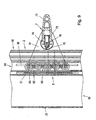
- the wiper strip 70 may be fastened in a separate profile holder 73, cf. Figure 9 , which in turn is optionally held horizontally displaceable in the housing 71.
- a roller 74 is rotatably mounted on each side of the wiper strip housing 71, these rollers 74 optionally at joint profile covers 75 or 75 'can come to rest and then via a connection of the roller shaft 76 ( Figure 9 ) with the wiper strip holder 73 may also, upon retraction of the rollers 74, an insertion of the profile holder 73 in the housing 71 can cause.
- Joint covers of various types are in Figure 4 shown at 75 and 75 'and 75'', from this Figure 4 it can be seen that the plate member 16 of the facade element 2 may optionally also be divided by horizontal joints and separating profiles, for example 77, 78, in a conventional manner per se.
- a middle rail 80 can be seen, which is arranged in the region between in each case two adjacent facade elements 2A, 2B and, via seals 81 which cooperate with seals 82 on the semi-profiles 18, 19, a sealing of the vertical joint 4 in the region between the half-profiles 18, 19 causes;
- the seals 81, 82 also provide a seal and guidance of the respective wiper strip support 61 when it moves up and down along the vertical narrow sides of the facade elements 2 and between the seals 81, 82.
- the center rail 80 is closed at its front by an internally toothed U-profile 83, and it is in cross-section, as seen from Fig.2 is apparent, substantially T-shaped, wherein the rear web 84 is held with the interposition of seals 85 in their own profile grooves 86.
- a middle rail 80 as from Figure 3 can be seen in each case already pre-assembled on a vertical side of a prefabricated facade element 2.
- the prefabricated Façade element 2 wears no wiper strip unit 7, but this was in Figure 3 for better illustration of the mutual association together with the drive means 29 already illustrated.
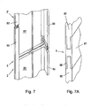
- the front mounted U-profile 83 for example, from a middle rail 80 of an in Figure 7 only with 2 indicated, incidentally not shown lower facade element can project upwards and is connected in the assembly with the middle rail 80 'of the then mounted thereon facade element 2', so as an exact alignment of the center rails 80, 80 'in the vertical direction despite to ensure the distance in the joint area 5.
- the center rail 80 'of the overlying facade element 2' has, in order to enable this, a starting offset with the lower end U-profile 83 '.
- the inner web portions 84 can be seen.
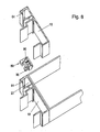
- Figure 8 shows diagrammatically a joint bridging piece 89 for the continuation of guide surfaces in the guide channels 64 of the half-profiles 18 and 19 between vertically stacked facade elements.
- the joint bridging piece 89 guides the roller elements 63 or sliders for the entrainment of the facade cleaning elements smoothly over the horizontal joints 5.
- protruding tabs 90 are arranged, which are easily inserted into the corresponding profile channel 27 at least one half-profile 18.
- the joint bridging piece 89 is fixed at least in one of the adjacent semi-profiles 18 and is against secured slipping.
- the procedure described in the installation of the described facade elements 2 that this, after its prefabrication with the attached to the plate members or glass panels 16, preferably made of aluminum semi-profiles 18, 19, 34, 35, optionally together with pre-assembled middle rails 80, U And / or joint bridging elements 87, etc., attached in sequence to each other and one above the other on a facade 3, wherein at the bottom of the facade 3, a series of semi-profiles similar to the half-profiles 35 may be attached to the bottom row of facade elements. 2 to attach first. After assembly of the facade elements 2, the drive means 29 together with driver parts 60 and cleaning element carriers 61 are mounted in the profile channels 27, 28, and the wiper strip units 7 are mounted.
- the horizontal joints 5 are, of course, only possible in the area of the superimposed plate parts 16 and vertical half profiles 18, 19, but not in the horizontal half profiles 34, 35, which are inserted into one another during installation. It would be conceivable, the plate members 16 as well as the vertical half-profiles 18, 19 directly abut each other when the facade elements 2 are mounted one above the other, however, the provision of the joints 5 or distances for aesthetic reasons, as well as in terms of any manufacturing tolerances desired or be necessary, for example, to prevent the abutting vertical half-profiles 18, 19 hinder the proper assembly of a facade element 2 over another, with telescoping of the respective horizontal half-profiles 34, 35 at a possible excess length.
- the height of the facade elements 2 will usually depend on the storey height of the respective building 1, since the suspension of the facade elements 2 is thus made possible on the carriers 46 recessed in the storey ceilings, without the necessity of attaching carriers to other locations.
Landscapes
- Engineering & Computer Science (AREA)
- Architecture (AREA)
- Civil Engineering (AREA)
- Structural Engineering (AREA)
- Chemical & Material Sciences (AREA)
- Electromagnetism (AREA)
- Physics & Mathematics (AREA)
- Chemical Kinetics & Catalysis (AREA)
- Electrochemistry (AREA)
- Mechanical Engineering (AREA)
- Finishing Walls (AREA)
- Load-Bearing And Curtain Walls (AREA)
- Pharmaceuticals Containing Other Organic And Inorganic Compounds (AREA)
Claims (23)
- Elément de façade préfabriqué (2) comprenant une partie de plaque généralement rectangulaire (16) et des éléments profilés appliqués dans des zones de bord de celle-ci, caractérisé en ce que les éléments profilés se présentent, sur au moins deux côtés étroits opposés l'un à l'autre (17) de la partie de plaque (16), sous la forme de demi-profilés de support (18, 19; 34, 35) ajustés par paires l'un dans l'autre, dépassant des zones de bord de la partie de plaque en règle générale perpendiculairement au côté arrière en position de fonctionnement, c'est-à-dire tourné vers le bâtiment avec des canaux profilés supplémentaires (27, 28) pour recevoir un moyen d'entraînement (29) pour un élément de nettoyage de façade de type essuie-glace (7).
- Elément de façade selon la revendication 1, caractérisé en ce qu'il est prévu, sur l'ensemble des quatre côtés de la partie de plaque (16), des demi-profilés de support ajustés par paires l'un dans l'autre (18, 19 ; 34, 35), parmi lesquels seule une paire de demi-profilés de support (18, 19) présente les canaux profilés (27, 28) pour recevoir un moyen d'entraînement (29).
- Elément de façade selon la revendication 2, caractérisé en ce que les demi-profilés de support (18, 19), qui sont prévus sur les côtés verticaux en position de fonctionnement, présentent les canaux profilés (27, 28).
- Elément de façade selon l'une quelconque des revendications 1 à 3, caractérisé en ce que les demi-profilés de support ajustés par paires l'un dans l'autre (18, 19 ; 34, 35) présentent des branches profilées (40 à 43) destinées à s'engager l'une dans l'autre par appui mutuel, dans lequel respectivement au moins l'une des branches profilées (23, 24) destinées respectivement à un appui mutuel porte un joint étanche (25, 26) pour un appui étanche sur la branche profilée correspondante (21, 22) d'un élément de façade voisin (2).
- Elément de façade selon l'une quelconque des revendications 1 à 4, caractérisé en ce qu'il est prévu respectivement deux canaux profilés (27, 28) pour recevoir respectivement un brin (30, 31) d'un moyen d'entraînement sans fin (29).
- Elément de façade selon la revendication 5, caractérisé en ce que le moyen d'entraînement sans fin (29) est une courroie dentée (32).
- Elément de façade selon l'une quelconque des revendications 1 à 6, caractérisé en ce que le canal profilé ou l'un (27) des deux canaux profilés (27, 28) du demi-profilé de support respectif (18, 19) présente une ouverture latérale (62') pour y faire passer une partie d'entraînement (62) pour l'élément de nettoyage de façade (7).
- Elément de façade selon l'une quelconque des revendications 1 à 7, caractérisé en ce que le canal profilé (27) ou l'un des deux canaux profilés du demi-profilé de support respectif (18, 19) forme un canal de guidage (64) pour au moins un élément de roulement ou de glissement (63) du moyen d'entraînement (29).
- Elément de façade selon la revendication 8, caractérisé en ce que l'un des semi-profilés de support (18, 19) présentant le canal de guidage (64) présente des pièces de pontage (89) introduites dans le canal profilé (27) et dépassant dans un interstice (5) présent en position de fonctionnement vers l'élément de façade voisin (2).
- Elément de façade selon la revendication 9, caractérisé en ce que les pièces de pontage (89) sont constituées de matériau synthétique.
- Elément de façade selon l'une quelconque des revendications 1 à 10, caractérisé en ce que l'un (19) des deux demi-profilés de support (18, 19) qui présentent les canaux profilés supplémentaires (27, 28) porte dans la zone du ou des canaux profilés un rail central (80) qui s'étend dans la zone du côté étroit (17) de la partie de plaque (16).
- Elément de façade selon la revendication 11, caractérisé en ce que le rail central (80) porte à une extrémité un élément de pontage d'interstice (87) à raccorder à un rail central (80') d'un élément de façade voisin.
- Elément de façade selon la revendication 11 ou 12 et la revendication 5, caractérisé en ce que le rail central en forme de barre (80) porte sur ses deux côtés longitudinaux des joints étanches (81) à appliquer sur les parties d'entraînement ou sur des supports d'élément de nettoyage (61) raccordés en position de fonctionnement aux parties d'entraînement voisines.
- Elément de façade selon l'une quelconque des revendications 11 à 13, caractérisé en ce que le rail central (80) présente une section transversale en forme de T et s'engage par sa nervure transversale (84) dans une rainure profilée (86) dans la zone du ou d'un canal profilé (28).
- Elément de façade selon la revendication 14, caractérisé en ce que la nervure transversale (84) s'engage dans la rainure profilée (86) en position intermédiaire d'un joint étanche (85).
- Elément de façade selon l'une quelconque des revendications 1 à 15, caractérisé en ce que les demi-profilés de support (18, 19 ; 34, 35) sont raccordés dans les zones de bord proches des côtés étroits (17) de la partie de plaque (16) à celle-ci par collage (33).
- Elément de façade selon l'une quelconque des revendications 1 à 16, caractérisé en ce que les demi-profilés de support (18, 19) verticaux en position de fonctionnement sont équipés de parties de raccordement saillantes (47) pour la fixation de préférence réglable à des supports fixes (46) du bâtiment.
- Elément de façade selon la revendication 17, caractérisé en ce que les parties de raccordement (47) se présentent sous la forme de crochets.
- Elément de façade selon la revendication 17 ou 18, caractérisé en ce que les parties de raccordement (47) contiennent des vis de réglage (57) pour le réglage fin de la hauteur de l'élément de façade (2) par rapport aux supports fixes (46) du bâtiment.
- Elément de façade selon l'une quelconque des revendications 1 à 19, caractérisé en ce que la partie de plaque (16) est un panneau de verre.
- Elément de façade selon l'une quelconque des revendications 1 à 20, caractérisé en ce que la partie de plaque (16) est un panneau de verre feuilleté.
- Elément de façade selon l'une quelconque des revendications 1 à 21, caractérisé en ce que la partie de plaque (16) est un panneau de verre isolant.
- Façade comprenant des éléments de façade selon l'une quelconque des revendications 1 à 22.
Priority Applications (1)
| Application Number | Priority Date | Filing Date | Title |
|---|---|---|---|
| AT06700102T ATE437274T1 (de) | 2005-01-12 | 2006-01-05 | Vorgefertigtes fassadenelement |
Applications Claiming Priority (2)
| Application Number | Priority Date | Filing Date | Title |
|---|---|---|---|
| AT0003605A AT501771B1 (de) | 2005-01-12 | 2005-01-12 | Vorgefertigtes fassadenelement |
| PCT/AT2006/000006 WO2006074492A1 (fr) | 2005-01-12 | 2006-01-05 | Element de façade prefabrique |
Publications (2)
| Publication Number | Publication Date |
|---|---|
| EP1836358A1 EP1836358A1 (fr) | 2007-09-26 |
| EP1836358B1 true EP1836358B1 (fr) | 2009-07-22 |
Family
ID=35744702
Family Applications (1)
| Application Number | Title | Priority Date | Filing Date |
|---|---|---|---|
| EP06700102A Expired - Lifetime EP1836358B1 (fr) | 2005-01-12 | 2006-01-05 | Element de façade prefabrique |
Country Status (10)
| Country | Link |
|---|---|
| US (1) | US20080141606A1 (fr) |
| EP (1) | EP1836358B1 (fr) |
| JP (1) | JP2008527206A (fr) |
| KR (1) | KR20070103448A (fr) |
| CN (1) | CN101103159A (fr) |
| AT (2) | AT501771B1 (fr) |
| CA (1) | CA2591928A1 (fr) |
| DE (1) | DE502006004297D1 (fr) |
| RU (1) | RU2007130672A (fr) |
| WO (1) | WO2006074492A1 (fr) |
Families Citing this family (12)
| Publication number | Priority date | Publication date | Assignee | Title |
|---|---|---|---|---|
| SE0800186L (sv) * | 2008-01-25 | 2009-07-26 | Brunkeberg Industriutveckling Ab | Ramsystem för uppbärande av fasadelement och metod för uppförande av fasadelement |
| SG172030A1 (en) * | 2008-12-19 | 2011-07-28 | Brunkeberg Industriutveckling Ab | A method for mounting facade elements on a multi-storey building |
| CN102444229B (zh) * | 2011-09-26 | 2013-08-07 | 北京城建亚泰建设工程有限公司 | 空间三向可调柔性幕墙连接件及其施工方法 |
| CA2981769C (fr) * | 2015-04-13 | 2023-09-26 | Henrik Falk | Element de facade et rail pour l'element de facade |
| CN106401033A (zh) * | 2016-11-22 | 2017-02-15 | 华东建筑设计研究院有限公司 | 能复合控制建筑幕墙的启闭与推送擦窗机进出的工作装置 |
| CN110905109B (zh) * | 2019-12-11 | 2021-03-26 | 广东大鹏幕墙科技有限公司 | 一种易于清洁的高层建筑玻璃幕墙 |
| CN111956118B (zh) * | 2020-08-07 | 2021-11-19 | 南京蹑波物联网科技有限公司 | 一种行走机器人 |
| CN112112331A (zh) * | 2020-09-22 | 2020-12-22 | 金华职业技术学院 | 一种能够调节的绿色节能建筑幕墙 |
| CN112112298B (zh) * | 2020-09-26 | 2022-01-28 | 南京上柏建筑设计咨询有限公司 | 一种建筑保温幕墙结构 |
| CN113463802B (zh) * | 2021-08-17 | 2022-04-29 | 江苏和源兴建设股份有限公司 | 一种悬挂式玻璃幕墙 |
| CN113818604B (zh) * | 2021-09-13 | 2022-08-26 | 河南津大幕墙有限公司 | 一种具有自清洁功能的通风型节能玻璃幕墙 |
| CN117027250A (zh) * | 2023-09-06 | 2023-11-10 | 中国建筑第二工程局有限公司 | 一种幕墙玻璃屋面系统 |
Family Cites Families (21)
| Publication number | Priority date | Publication date | Assignee | Title |
|---|---|---|---|---|
| US1410487A (en) * | 1920-04-05 | 1922-03-21 | Mccarty Elonzo Clarence | Window |
| US1766550A (en) * | 1929-03-02 | 1930-06-24 | Alma Adele Lindquist | Automatic window cleaner |
| US1803722A (en) * | 1929-04-22 | 1931-05-05 | Morris R Moon | Automatic window cleaner |
| US3354494A (en) * | 1965-06-25 | 1967-11-28 | Lockheed Aircraft Corp | Window wiper mechanism |
| US3378875A (en) * | 1966-05-17 | 1968-04-23 | Eugene E. Kern | Window cleaning device |
| JPS5317819B2 (fr) * | 1972-04-12 | 1978-06-10 | ||
| US4257138A (en) * | 1979-07-23 | 1981-03-24 | Nicholas Clements | Automatic device for washing windows |
| JP2854152B2 (ja) * | 1991-03-20 | 1999-02-03 | 株式会社竹中工務店 | ガラスカーテンウォールの取付け構造 |
| EP0538521B1 (fr) * | 1991-10-23 | 1997-10-01 | Aston International Limited | Appareil de nettoyage pour toiture vitrée |
| US5353466A (en) * | 1991-12-04 | 1994-10-11 | Smith Darrel L | Rearview mirror wiper |
| JP2822116B2 (ja) * | 1992-10-23 | 1998-11-11 | ワイケイケイアーキテクチュラルプロダクツ株式会社 | ユニット式カーテンウオール |
| DE4336142A1 (de) * | 1993-10-22 | 1995-04-27 | Pilz Technologie Gmbh | Fassadenkonstruktion sowie Arbeitsaufzug und Verfahren zu ihrer Montage |
| JPH08117154A (ja) * | 1994-10-27 | 1996-05-14 | Katsuaki Tomita | ビルディング外壁の自動清掃方法とその装置 |
| US5699576A (en) * | 1995-04-07 | 1997-12-23 | Robert S. Tomko | Exterior window cleaning apparatus |
| JP3661139B2 (ja) * | 1998-04-28 | 2005-06-15 | Ykk Ap株式会社 | ユニット式カーテンウオール |
| JPH11336233A (ja) * | 1998-05-27 | 1999-12-07 | Ykk Architectural Products Inc | カーテンウォールユニット、ユニット式カーテンウォール、カーテンウォールユニットの取付装置および取付方法 |
| AT406730B (de) * | 1998-09-10 | 2000-08-25 | Thurnher Julius | Reinigungsvorrichtung für die flügel von schiebefenstern oder -türen |
| AT407067B (de) * | 1998-12-10 | 2000-12-27 | Thurnher Julius | Antriebseinrichtung für einen schiebeflügel |
| AT411728B (de) * | 1999-12-16 | 2004-05-25 | Thurnher Julius | Reinigungsvorrichtung für eine fassadenfläche |
| IT1320562B1 (it) * | 2000-07-28 | 2003-12-10 | Salvatore Butindari | Unita' di lavaggio automatizzato per finestre. |
| US6851156B1 (en) * | 2002-02-21 | 2005-02-08 | Cheryl Hairaton | Window sky scraper |
-
2005
- 2005-01-12 AT AT0003605A patent/AT501771B1/de not_active IP Right Cessation
-
2006
- 2006-01-05 RU RU2007130672/03A patent/RU2007130672A/ru not_active Application Discontinuation
- 2006-01-05 CN CNA200680002217XA patent/CN101103159A/zh active Pending
- 2006-01-05 CA CA002591928A patent/CA2591928A1/fr not_active Abandoned
- 2006-01-05 WO PCT/AT2006/000006 patent/WO2006074492A1/fr not_active Ceased
- 2006-01-05 EP EP06700102A patent/EP1836358B1/fr not_active Expired - Lifetime
- 2006-01-05 JP JP2007549759A patent/JP2008527206A/ja active Pending
- 2006-01-05 AT AT06700102T patent/ATE437274T1/de active
- 2006-01-05 DE DE502006004297T patent/DE502006004297D1/de not_active Expired - Lifetime
- 2006-01-05 US US11/794,997 patent/US20080141606A1/en not_active Abandoned
- 2006-01-05 KR KR1020077018518A patent/KR20070103448A/ko not_active Ceased
Also Published As
| Publication number | Publication date |
|---|---|
| CA2591928A1 (fr) | 2006-07-20 |
| RU2007130672A (ru) | 2009-02-20 |
| US20080141606A1 (en) | 2008-06-19 |
| CN101103159A (zh) | 2008-01-09 |
| DE502006004297D1 (de) | 2009-09-03 |
| AT501771A1 (de) | 2006-11-15 |
| WO2006074492A1 (fr) | 2006-07-20 |
| EP1836358A1 (fr) | 2007-09-26 |
| KR20070103448A (ko) | 2007-10-23 |
| ATE437274T1 (de) | 2009-08-15 |
| JP2008527206A (ja) | 2008-07-24 |
| AT501771B1 (de) | 2007-03-15 |
Similar Documents
| Publication | Publication Date | Title |
|---|---|---|
| DE69528547T2 (de) | System beinhaltend vorgefertigte Platten für Bauten und Konstruktion | |
| DE69722881T2 (de) | Gebäude Konstruktion | |
| EP0410993B1 (fr) | Bloc de construction pour facade en verre | |
| EP1836358B1 (fr) | Element de façade prefabrique | |
| EP0147502B1 (fr) | Couverture avec au moins un élément de toit mobile | |
| EP3199738A2 (fr) | Système de retenue de rambarde en verre et partie de renfort destinée à être utilisée dans un tel système | |
| DE2316876A1 (de) | Zusammenlegbare trennwand zum unterteilen von raeumen | |
| EP1273749B1 (fr) | Elément coulissant | |
| DE19960535A1 (de) | Trennwandaufbau | |
| AT404373B (de) | Horizontaler rahmenschenkel für einen rahmen für eine trennwand | |
| DE4031388C2 (de) | Seitensektionaltor oder Rundlauftor, Deckensektionaltor | |
| DE4433635A1 (de) | Schiebetür oder -tor | |
| EP2366856A2 (fr) | Agencement de porte coulissante dotée d'un obturateur et procédé d'agencement d'un obturateur | |
| DE2644559A1 (de) | Aus- und umbaubare trennwand | |
| EP2687666B1 (fr) | Module pour la réception d'une porte coulissante et procédé de montage d'un module pour une porte coulissante | |
| DE69406949T2 (de) | Modulares system zum errichten von fassaden | |
| AT503330B1 (de) | Profilschieneneinrichtung für eine mit glastafeln aufgebaute gebäude-fassade sowie glastafel hiefür | |
| EP1870549A2 (fr) | Porte sectionnelle | |
| EP0213451B1 (fr) | Rail pour une construction de support d'un bardage de mur ou plafond | |
| DE2404526C2 (de) | Verbindungselement zur Befestigung von Wandelementen | |
| DE10313391B4 (de) | Duschwanne sowie Herstellungsverfahren und Duschkabine | |
| EP1857605B1 (fr) | Revêtement de sol pour partie de bâtiment | |
| DE202007018281U1 (de) | Trennleistenvorrichtung | |
| EP1260644A2 (fr) | Elément de toiture, bâtiment et procédé pour construire un tel bâtiment | |
| EP2304151B1 (fr) | Profilé de cadre, dormant et cadre de porte de garage |
Legal Events
| Date | Code | Title | Description |
|---|---|---|---|
| PUAI | Public reference made under article 153(3) epc to a published international application that has entered the european phase |
Free format text: ORIGINAL CODE: 0009012 |
|
| 17P | Request for examination filed |
Effective date: 20070803 |
|
| AK | Designated contracting states |
Kind code of ref document: A1 Designated state(s): AT BE BG CH CY CZ DE DK EE ES FI FR GB GR HU IE IS IT LI LT LU LV MC NL PL PT RO SE SI SK TR |
|
| DAX | Request for extension of the european patent (deleted) | ||
| GRAP | Despatch of communication of intention to grant a patent |
Free format text: ORIGINAL CODE: EPIDOSNIGR1 |
|
| GRAS | Grant fee paid |
Free format text: ORIGINAL CODE: EPIDOSNIGR3 |
|
| GRAA | (expected) grant |
Free format text: ORIGINAL CODE: 0009210 |
|
| AK | Designated contracting states |
Kind code of ref document: B1 Designated state(s): AT BE BG CH CY CZ DE DK EE ES FI FR GB GR HU IE IS IT LI LT LU LV MC NL PL PT RO SE SI SK TR |
|
| REG | Reference to a national code |
Ref country code: GB Ref legal event code: FG4D Free format text: NOT ENGLISH |
|
| REG | Reference to a national code |
Ref country code: CH Ref legal event code: EP |
|
| REG | Reference to a national code |
Ref country code: IE Ref legal event code: FG4D |
|
| REF | Corresponds to: |
Ref document number: 502006004297 Country of ref document: DE Date of ref document: 20090903 Kind code of ref document: P |
|
| NLV1 | Nl: lapsed or annulled due to failure to fulfill the requirements of art. 29p and 29m of the patents act | ||
| PG25 | Lapsed in a contracting state [announced via postgrant information from national office to epo] |
Ref country code: SE Free format text: LAPSE BECAUSE OF FAILURE TO SUBMIT A TRANSLATION OF THE DESCRIPTION OR TO PAY THE FEE WITHIN THE PRESCRIBED TIME-LIMIT Effective date: 20090722 Ref country code: LT Free format text: LAPSE BECAUSE OF FAILURE TO SUBMIT A TRANSLATION OF THE DESCRIPTION OR TO PAY THE FEE WITHIN THE PRESCRIBED TIME-LIMIT Effective date: 20090722 Ref country code: ES Free format text: LAPSE BECAUSE OF FAILURE TO SUBMIT A TRANSLATION OF THE DESCRIPTION OR TO PAY THE FEE WITHIN THE PRESCRIBED TIME-LIMIT Effective date: 20091102 Ref country code: FI Free format text: LAPSE BECAUSE OF FAILURE TO SUBMIT A TRANSLATION OF THE DESCRIPTION OR TO PAY THE FEE WITHIN THE PRESCRIBED TIME-LIMIT Effective date: 20090722 Ref country code: IS Free format text: LAPSE BECAUSE OF FAILURE TO SUBMIT A TRANSLATION OF THE DESCRIPTION OR TO PAY THE FEE WITHIN THE PRESCRIBED TIME-LIMIT Effective date: 20091122 |
|
| PG25 | Lapsed in a contracting state [announced via postgrant information from national office to epo] |
Ref country code: NL Free format text: LAPSE BECAUSE OF FAILURE TO SUBMIT A TRANSLATION OF THE DESCRIPTION OR TO PAY THE FEE WITHIN THE PRESCRIBED TIME-LIMIT Effective date: 20090722 Ref country code: LV Free format text: LAPSE BECAUSE OF FAILURE TO SUBMIT A TRANSLATION OF THE DESCRIPTION OR TO PAY THE FEE WITHIN THE PRESCRIBED TIME-LIMIT Effective date: 20090722 Ref country code: PL Free format text: LAPSE BECAUSE OF FAILURE TO SUBMIT A TRANSLATION OF THE DESCRIPTION OR TO PAY THE FEE WITHIN THE PRESCRIBED TIME-LIMIT Effective date: 20090722 Ref country code: SI Free format text: LAPSE BECAUSE OF FAILURE TO SUBMIT A TRANSLATION OF THE DESCRIPTION OR TO PAY THE FEE WITHIN THE PRESCRIBED TIME-LIMIT Effective date: 20090722 |
|
| REG | Reference to a national code |
Ref country code: IE Ref legal event code: FD4D |
|
| PG25 | Lapsed in a contracting state [announced via postgrant information from national office to epo] |
Ref country code: PT Free format text: LAPSE BECAUSE OF FAILURE TO SUBMIT A TRANSLATION OF THE DESCRIPTION OR TO PAY THE FEE WITHIN THE PRESCRIBED TIME-LIMIT Effective date: 20091122 Ref country code: BG Free format text: LAPSE BECAUSE OF FAILURE TO SUBMIT A TRANSLATION OF THE DESCRIPTION OR TO PAY THE FEE WITHIN THE PRESCRIBED TIME-LIMIT Effective date: 20091022 |
|
| PG25 | Lapsed in a contracting state [announced via postgrant information from national office to epo] |
Ref country code: DK Free format text: LAPSE BECAUSE OF FAILURE TO SUBMIT A TRANSLATION OF THE DESCRIPTION OR TO PAY THE FEE WITHIN THE PRESCRIBED TIME-LIMIT Effective date: 20090722 Ref country code: RO Free format text: LAPSE BECAUSE OF FAILURE TO SUBMIT A TRANSLATION OF THE DESCRIPTION OR TO PAY THE FEE WITHIN THE PRESCRIBED TIME-LIMIT Effective date: 20090722 Ref country code: CZ Free format text: LAPSE BECAUSE OF FAILURE TO SUBMIT A TRANSLATION OF THE DESCRIPTION OR TO PAY THE FEE WITHIN THE PRESCRIBED TIME-LIMIT Effective date: 20090722 Ref country code: IE Free format text: LAPSE BECAUSE OF FAILURE TO SUBMIT A TRANSLATION OF THE DESCRIPTION OR TO PAY THE FEE WITHIN THE PRESCRIBED TIME-LIMIT Effective date: 20090722 Ref country code: EE Free format text: LAPSE BECAUSE OF FAILURE TO SUBMIT A TRANSLATION OF THE DESCRIPTION OR TO PAY THE FEE WITHIN THE PRESCRIBED TIME-LIMIT Effective date: 20090722 |
|
| PLBE | No opposition filed within time limit |
Free format text: ORIGINAL CODE: 0009261 |
|
| STAA | Information on the status of an ep patent application or granted ep patent |
Free format text: STATUS: NO OPPOSITION FILED WITHIN TIME LIMIT |
|
| PG25 | Lapsed in a contracting state [announced via postgrant information from national office to epo] |
Ref country code: SK Free format text: LAPSE BECAUSE OF FAILURE TO SUBMIT A TRANSLATION OF THE DESCRIPTION OR TO PAY THE FEE WITHIN THE PRESCRIBED TIME-LIMIT Effective date: 20090722 |
|
| 26N | No opposition filed |
Effective date: 20100423 |
|
| BERE | Be: lapsed |
Owner name: THURNHER, JULIUS Effective date: 20100131 |
|
| PG25 | Lapsed in a contracting state [announced via postgrant information from national office to epo] |
Ref country code: MC Free format text: LAPSE BECAUSE OF NON-PAYMENT OF DUE FEES Effective date: 20100131 |
|
| REG | Reference to a national code |
Ref country code: CH Ref legal event code: PL |
|
| GBPC | Gb: european patent ceased through non-payment of renewal fee |
Effective date: 20100105 |
|
| PG25 | Lapsed in a contracting state [announced via postgrant information from national office to epo] |
Ref country code: CH Free format text: LAPSE BECAUSE OF NON-PAYMENT OF DUE FEES Effective date: 20100131 Ref country code: GR Free format text: LAPSE BECAUSE OF FAILURE TO SUBMIT A TRANSLATION OF THE DESCRIPTION OR TO PAY THE FEE WITHIN THE PRESCRIBED TIME-LIMIT Effective date: 20091023 Ref country code: LI Free format text: LAPSE BECAUSE OF NON-PAYMENT OF DUE FEES Effective date: 20100131 |
|
| PG25 | Lapsed in a contracting state [announced via postgrant information from national office to epo] |
Ref country code: GB Free format text: LAPSE BECAUSE OF NON-PAYMENT OF DUE FEES Effective date: 20100105 |
|
| PG25 | Lapsed in a contracting state [announced via postgrant information from national office to epo] |
Ref country code: BE Free format text: LAPSE BECAUSE OF NON-PAYMENT OF DUE FEES Effective date: 20100131 |
|
| PG25 | Lapsed in a contracting state [announced via postgrant information from national office to epo] |
Ref country code: IT Free format text: LAPSE BECAUSE OF FAILURE TO SUBMIT A TRANSLATION OF THE DESCRIPTION OR TO PAY THE FEE WITHIN THE PRESCRIBED TIME-LIMIT Effective date: 20090722 |
|
| PGFP | Annual fee paid to national office [announced via postgrant information from national office to epo] |
Ref country code: FR Payment date: 20110121 Year of fee payment: 6 |
|
| PG25 | Lapsed in a contracting state [announced via postgrant information from national office to epo] |
Ref country code: CY Free format text: LAPSE BECAUSE OF FAILURE TO SUBMIT A TRANSLATION OF THE DESCRIPTION OR TO PAY THE FEE WITHIN THE PRESCRIBED TIME-LIMIT Effective date: 20090722 |
|
| PG25 | Lapsed in a contracting state [announced via postgrant information from national office to epo] |
Ref country code: HU Free format text: LAPSE BECAUSE OF FAILURE TO SUBMIT A TRANSLATION OF THE DESCRIPTION OR TO PAY THE FEE WITHIN THE PRESCRIBED TIME-LIMIT Effective date: 20100123 Ref country code: LU Free format text: LAPSE BECAUSE OF NON-PAYMENT OF DUE FEES Effective date: 20100105 |
|
| REG | Reference to a national code |
Ref country code: FR Ref legal event code: ST Effective date: 20120928 |
|
| PG25 | Lapsed in a contracting state [announced via postgrant information from national office to epo] |
Ref country code: TR Free format text: LAPSE BECAUSE OF FAILURE TO SUBMIT A TRANSLATION OF THE DESCRIPTION OR TO PAY THE FEE WITHIN THE PRESCRIBED TIME-LIMIT Effective date: 20090722 |
|
| PG25 | Lapsed in a contracting state [announced via postgrant information from national office to epo] |
Ref country code: FR Free format text: LAPSE BECAUSE OF NON-PAYMENT OF DUE FEES Effective date: 20120131 |
|
| PGFP | Annual fee paid to national office [announced via postgrant information from national office to epo] |
Ref country code: DE Payment date: 20130110 Year of fee payment: 8 |
|
| PGFP | Annual fee paid to national office [announced via postgrant information from national office to epo] |
Ref country code: AT Payment date: 20130125 Year of fee payment: 8 |
|
| REG | Reference to a national code |
Ref country code: DE Ref legal event code: R119 Ref document number: 502006004297 Country of ref document: DE |
|
| REG | Reference to a national code |
Ref country code: AT Ref legal event code: MM01 Ref document number: 437274 Country of ref document: AT Kind code of ref document: T Effective date: 20140105 |
|
| REG | Reference to a national code |
Ref country code: DE Ref legal event code: R119 Ref document number: 502006004297 Country of ref document: DE Effective date: 20140801 |
|
| PG25 | Lapsed in a contracting state [announced via postgrant information from national office to epo] |
Ref country code: DE Free format text: LAPSE BECAUSE OF NON-PAYMENT OF DUE FEES Effective date: 20140801 |
|
| PG25 | Lapsed in a contracting state [announced via postgrant information from national office to epo] |
Ref country code: AT Free format text: LAPSE BECAUSE OF NON-PAYMENT OF DUE FEES Effective date: 20140105 |