EP1836783B1 - Verfahren und vorrichtungen zur optischen drahtlosen kommunikation - Google Patents
Verfahren und vorrichtungen zur optischen drahtlosen kommunikation Download PDFInfo
- Publication number
- EP1836783B1 EP1836783B1 EP05852973.6A EP05852973A EP1836783B1 EP 1836783 B1 EP1836783 B1 EP 1836783B1 EP 05852973 A EP05852973 A EP 05852973A EP 1836783 B1 EP1836783 B1 EP 1836783B1
- Authority
- EP
- European Patent Office
- Prior art keywords
- video data
- optical wireless
- video
- laser beam
- wireless receiver
- Prior art date
- Legal status (The legal status is an assumption and is not a legal conclusion. Google has not performed a legal analysis and makes no representation as to the accuracy of the status listed.)
- Ceased
Links
Images




Classifications
-
- H—ELECTRICITY
- H04—ELECTRIC COMMUNICATION TECHNIQUE
- H04B—TRANSMISSION
- H04B10/00—Transmission systems employing electromagnetic waves other than radio-waves, e.g. infrared, visible or ultraviolet light, or employing corpuscular radiation, e.g. quantum communication
- H04B10/11—Arrangements specific to free-space transmission, i.e. transmission through air or vacuum
- H04B10/114—Indoor or close-range type systems
- H04B10/1143—Bidirectional transmission
-
- H—ELECTRICITY
- H04—ELECTRIC COMMUNICATION TECHNIQUE
- H04N—PICTORIAL COMMUNICATION, e.g. TELEVISION
- H04N21/00—Selective content distribution, e.g. interactive television or video on demand [VOD]
- H04N21/40—Client devices specifically adapted for the reception of or interaction with content, e.g. set-top-box [STB]; Operations thereof
- H04N21/41—Structure of client; Structure of client peripherals
- H04N21/4104—Peripherals receiving signals from specially adapted client devices
- H04N21/4122—Peripherals receiving signals from specially adapted client devices additional display device, e.g. video projector
-
- H—ELECTRICITY
- H04—ELECTRIC COMMUNICATION TECHNIQUE
- H04N—PICTORIAL COMMUNICATION, e.g. TELEVISION
- H04N21/00—Selective content distribution, e.g. interactive television or video on demand [VOD]
- H04N21/40—Client devices specifically adapted for the reception of or interaction with content, e.g. set-top-box [STB]; Operations thereof
- H04N21/43—Processing of content or additional data, e.g. demultiplexing additional data from a digital video stream; Elementary client operations, e.g. monitoring of home network or synchronising decoder's clock; Client middleware
- H04N21/436—Interfacing a local distribution network, e.g. communicating with another STB or one or more peripheral devices inside the home
- H04N21/4367—Establishing a secure communication between the client and a peripheral device or smart card
-
- H—ELECTRICITY
- H04—ELECTRIC COMMUNICATION TECHNIQUE
- H04N—PICTORIAL COMMUNICATION, e.g. TELEVISION
- H04N7/00—Television systems
- H04N7/16—Analogue secrecy systems; Analogue subscription systems
- H04N7/162—Authorising the user terminal, e.g. by paying; Registering the use of a subscription channel, e.g. billing
- H04N7/163—Authorising the user terminal, e.g. by paying; Registering the use of a subscription channel, e.g. billing by receiver means only
-
- H—ELECTRICITY
- H04—ELECTRIC COMMUNICATION TECHNIQUE
- H04N—PICTORIAL COMMUNICATION, e.g. TELEVISION
- H04N7/00—Television systems
- H04N7/22—Adaptations for optical transmission
Definitions
- the present invention relates generally to optical wireless communication, and in particular to wireless optical delivery of a video signal.
- the preferred consumer digital video interfaces are High Definition Multimedia Interface (HDMI) and Digital Visual Interface (DVI).
- DVI is commonly used by PC equipment to drive digital video displays.
- DVI typically supports 24-bit RGB at video rates up to 165MHz.
- a DVI driver accepts 24-bit RGB data and serializes it into three serial channels. The video clock is added as a fourth channel.
- RGB data is serialized, it is encoded using an 8b/10b encoding scheme called Transition Minimized Differential Signaling (TMDS).
- TMDS Transition Minimized Differential Signaling
- HDMI is backwards compatible with DVI. It supports alternate (non-RGB) color spaces and includes the ability to carry digital audio.
- HDMI data is encoded to represent active video periods and control periods.
- HDMI includes a third entity called a Data Island. Data Islands are used to communicate additional data during the blanking interval. For example, data islands are used to send digital audio data in HDMI.
- Data delivered using a DVI or HDMI interface may be encrypted using High-Bandwidth Digital-Content Protection (HDCP).
- HDCP High-Bandwidth Digital-Content Protection
- Implementation of HDCP requires a set of unique secret device keys.
- the receiver will only receive content once it demonstrates knowledge of the keys.
- the transmitter and receiver will generate a shared secret value that is consistently checked throughout the transmission. Once authentication is established, the transmitter encrypts the data and sends it to the receiver for decryption.
- DVI/HDMI data has only been deliverable using hard wires due at least in part to the way the data source and the display device need to communicate with each other.
- a display device such as a flat-panel television
- the video source e.g., receiver or DVD player
- the consumer would typically be required to purchase and install DVI cabling from the video source to the display.
- this may be both costly and present difficult installation issues.
- a wireless radio frequency (RF) system could be used between a video source and a display device.
- RF radio frequency
- the hardware required for an optical wireless signal may be less complex than a RF system.
- a wireless optical solution is more secure since it will not penetrate walls as with an RF system.
- a wireless optical system which eliminates the need for cabling between a digital video source and a digital video sink may be desirable.
- a system includes a video data source having a source output, an optical wireless transmitter to receive video data from the source output and encode the video data into a laser beam, and an optical wireless receiver to receive the laser beam and to extract the video data there from.
- the method further includes a display device having a destination input, wherein the display device receives the video data from the optical wireless receiver and presents a video display based on said video data.
- One aspect of the invention is to provide a wireless optical video system in which video content (e.g., DVI or HDMI) is wirelessly transmitted between a digital video source and a display device.
- video content e.g., DVI or HDMI
- this wireless optical communication is accomplished using a laser, encoded with the digital video data, directed from an optical transmitter to an optical receiver.
- the data to be communicated includes high-definition video content.
- Another aspect of the invention is to use a collimating lens to focus a wireless optical signal onto the focusing lens of a receiver. While in one embodiment, the laser beam to be transmitted is between approximately 1/4 inch to approximately 1/2 inch, it should equally be appreciated that the beam may equally have a thicker or thinner diameter.
- Another aspect of the invention is to provide the video data to the display at the same resolution and with the same video clock speed as that of the video source.
- HDMI and DVI provide a mechanism for the video source to query the video sink as to what video formats are supported. Once queried, the video source may select the "best" video format for sending video data to the display. This selected video format may then be passed from the video source, through a wireless optical link, and on to a display device.
- the invention also makes use of a control channel communication system to enable DVI and HDMI content to be transmitted wirelessly.
- DVI/HDMI data has only been deliverable using hard wires given that the data source and the display device are required to actively communicate with each other.
- this control channel communication system is provided by a low data-rate 2.4GHz RF link.
- a control-channel communication system may be implemented with an alternate technology, such as for example an Infrared optical communication link.
- HDMI/DVI content and system components While much of the following description is in terms of HDMI/DVI content and system components, it should equally be appreciated that the principles of the invention are not limited and such, and may be applied to any other type of video content, such as serial digital interface (SDI) and high-definition serial digital interface (HD SDI).
- SDI serial digital interface
- HD SDI high-definition serial digital interface
- a video source 110 may be coupled to an optical transmitter 120.
- the video source is an HDMI/DVI video source, such as an ATSC tuner, DVD player, etc.
- the video source 110 is a high-definition video source.
- the video source 110 may be any known video source (e.g., HD SDI, 1080i, 720p, 480p, 480i, standard definition, etc.).
- the signal provided to the optical transmitter 120 by the video source 110 may be encrypted with a copyright protection protocol, such as High-bandwidth Digital Content Protection (HDCP).
- HDCP High-bandwidth Digital Content Protection
- the video source 110 provides video data to the optical transmitter 120, which in turn provides a wireless optical signal 130 to optical receiver 140.
- this optical signal 130 may be encoded with the video data being provided by the video source 110.
- the optical signal 130 contains uncompressed high-definition video data. Once the video data is received by receiver 140, it may be decoded for display device 150.
- Transmitter 200 of FIG. 2 is a more detailed diagram of one embodiment of the optical transmitter 120 of FIG. 1 .
- Transmitter 200 which receives the video signal from data source 110, is depicted as including a DVI/HDMI receiver 210, a transmitter circuit 220, a system clock 230 and a transmitter electro-optical interface 240.
- the data source 110 is an HDMI or DVI video source (e.g., ATSC tuner, DVD player, etc.), it may similarly be another type of data source.
- the data source 110 provides a digital signal to the DVI/HDMI receiver 210.
- the DVI/HDMI receiver 210 may be used to convert the DVI/HDMI digital signal from the data source 110 into a digital video signal, such as 24-bit RGB. DVI/HDMI receivers are known in the field and beyond the scope of this disclosure.
- the DVI/HDMI receiver 210 and the transmitter circuit 220 may be combined into a single logical circuit. While in one embodiment, the transmitter circuit 220 is a Field Programmable Gate Array (FPGA) or an Application-Specific Integrated Circuit (ASIC), it may similarly have other implementations.
- the other input for the transmitter circuit 220 comes from the system clock 230, which provides a clock signal.
- this clock signal is a 110 MHz signal.
- the output of the transmitter circuit 220 is to a transmitter electro-optical interface 240.
- One embodiment of the transmitter circuit 220 will be described in more detail below with reference to FIG. 4 , while one embodiment of the transmitter electro-optical interface 240 is described in more detail below with reference to FIG. 5 .
- Receiver 250 of FIG. 3 is a more detailed diagram of one embodiment of the optical receiver 140 of FIG. 1 .
- optical receiver 250 which receives the optical signal 130 from optical transmitter 120, is depicted as including a receiver electro-optical interface 260, a receiving circuit 270, a phase lock loop (PLL) 280, a DVI/HDMI transmitter 290, and a system clock 300.
- the optical transmitter 250 is further depicted as outputting video data to display device 150. While in one embodiment, the digital video data output to the display device 150 is one of HDMI and DVI data, it may similarly be another type of data.
- the optical receiver 250 includes a DVI/HDMI transmitter 290, the details of which are known in the field and beyond the scope of this disclosure.
- the DVI/HDMI transmitter 290 and the receiver circuit 270 may be combined into a single logical circuit.
- another input to the receiver circuit 270 comes from the system clock 300, which provides a clock signal. In one embodiment, this clock signal is a 110 MHz signal.
- the transmitter circuit 270 is further depicted as being in communication with PLL 280, which may be used to help regenerate the video clock of the DVI/HDMI transmitter 290.
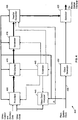
- transmitter circuit 400 includes a front end 405 which may be used to receive digital video data (such as 24-bit RGB) with control data from HDMI/DVI receiver 210, and optional ancillary data.
- the front end 405 may then output a near continuous stream of data to the optional RS (Reed-Solomon) Encoder 410.
- this data is a 20-bit stream output at 110MHz. If the incoming video data rate is insufficient to satisfy the RS Encoder 410, null words may be generated such that the RS Encoder 410 is never starved for data.
- the RS Encoder 410 may be comprised of two 10-bit encoders that apply an RS code of (216,200).
- the RS Encoders 410 may each accept 200 10-bit words of data and add 16 words of forward error correction (FEC) data. This coding scheme enables the receiver to correct up to eight errors in each RS block of 216 words. In another embodiment, forward error correction may not be performed.
- FEC forward error correction
- the RS Encoder may then output the data to the scrambler 415, which randomizes the data.
- the scrambler 415 may randomize the data to ensure that frequent transitions occur in the data stream. Frequent transitions help the receiver 270 synchronize itself to the 2.2GHz bit clock and recover the data.
- the scrambler 415 may use a pseudo-random number (PRN) generator to create a 20-bit random number for each 20-bit word. The incoming word is exclusive-OR'ed with the random number to produce a scrambled output.
- PRN pseudo-random number
- an identical PRN generator may be used on the receiver-side to unscramble the data.
- the header generator 420 may be used to output a word header. For example, in one embodiment, every 20uS the header generator 420 may output a 40 word header.
- a first portion of this header (e.g., first 20 words) may be comprised of preset data used to synchronize the receiver, followed by a second portion (e.g., next 20 words) of variable data, which can include control information for the receiver-side.
- the serializer 425 receives the data stream from the header generator, according to one embodiment.
- the serializer 425 is used to accept the encoded data in parallel and shift it out a bit at a time.
- the serializer 425 outputs a high rate video data stream to the transmitter electro-optical interface 240.
- the clock generator 430 synthesizes a clock (e.g., 2.2GHz) used by the serializer 425 for shifting the parallel data though the system based on the clock signal 435 (e.g., 110MHz) provided by a system clock (e.g., system clock 230).
- 2.2GHz may be used when electro-optical system 500 is tuned to operate at this specific bit rate.
- a 2.2 GHz bit rate may be used because it is exactly 20 times the 110 MHz clock rate.
- the controller 440 may be used to synchronize the various components of the transmitter circuit 400. In one embodiment, it may inform the header generator 420 when to generate a header. It may also initialize the PRN generator in the scrambler 415. Moreover, the controller 440 may also start the RS Encoder 410 such that its output will be present at the proper time. In one embodiment, the controller 440 may also inform the front end 405 when data must be available to the RS Encoder 410. In the embodiment of FIG. 4 , the controller 440 outputs a clock to the video clock analyzer (VCA) 445.
- VCA video clock analyzer
- the VCA 445 may be used to count the number of video clocks per time interval, with the resulting count "n" being transmitted to the receiver-side as part of the header's variable data. In one embodiment, "n" may be used on the receiver-side to regenerate the video clock.
- FIG. 5 depicted is a block diagram of one embodiment of an electro-optical system 500, which includes the transmitting electro-optical interface 240 of FIG. 2 communicating with the receiving electro-optical interface 260 of FIG. 3 .
- the transmitting electro-optical interface 240 provides an optical signal 550 which is received by the receiving electro-optical interface 260.
- the transmitting circuit 220 provides the video signal in the form of a digital electrical signal to the laser driver 510 which, in turn, generates a series of electrical potentials to the laser diode 520. This sequence of electrical potentials is used by the laser diode 520 to convert the signal into an optical signal 550.
- a collimating lens 530 may be used to focus the optical signal 550 such that it is properly receivable by the receiving electro-optical interface 260.
- a focusing lens 540 may be used to capture and focus the optical signal 550 onto a photo diode 560.
- the photo diode 560 receives and converts the optical signal 550 into a digital electrical signal which may then be passed to a trans-impedance amp 570 and then to a limiting amp 580.
- FIG. 6 depicted is a block diagram of a particular embodiment of the receiver circuit 270 of FIG. 3 .
- data is received by the receiver circuit 600 into a clock/data recovery block 610 from the receiver electo-optical interface 260.
- the function of the clock/data recovery block 610 is to extract the original transmit clock (e.g., 2.2GHz) and divide it down to reproduce the transmitter's system clock 230 (e.g., 110MHz) for use in moving the data through the receiver circuit 600.
- clock/data recovery block 610 may also deserialize the data to determine where one word ends and the next begins within the serial data stream.
- the header detector 620 may be used to search for the headers previously inserted by the transmitter circuit's header generator 420. When the header is found, the header detector 620 may signal the controller 630 to synchronize itself with the data stream. Once synchronized, the controller 630 may synchronize the other processing blocks in the receiver circuit 600.
- the descrambler 640 may contain a PRN generator that is initialized by the controller 630 at the proper time such that the data following the header is restored to its pre-scrambled values.
- the RS Decoder 650 is used to decode the data, followed by final processing and demultiplexing by a back-end 660, which is complimentary to the previously-described front end 405.
- the backend 660 is responsible for taking the data stream and extracting the original video and control data.
- one aspect of the invention is to provide the video data to the display 150 at the same resolution and with the same video clock speed as that of the video source 110.
- HDMI and DVI provide a mechanism for the video source 110 to query the video display 150 (sink) as to what video formats are supported. Once queried, the video source 110 may select the "best" video format for sending video data to the display 150. As will be described in more detail below, this query communication may be performed over an I2C link.
- the electro-optical system 500 has no way of knowing what video format will be selected by the video source 110. For this reason, the electro-optical system 500 will be able to accommodate any arbitrary clock rate, according to one embodiment.
- the video data is transmitted from the video source 110 through the electro-optical system 500 and to the display 150 in what ever format and with the appropriate video clock, as determined by the source 110. In one embodiment, this is accomplished by regenerating the video clock in the receiver 140.
- the flow of video data through the system is isochronous and the regenerated video clock must be phase-locked to the source's video clock.
- Video clock regeneration may be accomplished using a video clock counter in the transmitter (e.g., video clock analyzer 445) and a special PLL (e.g., PLL 280) in the receiver coupled to the video clock generator 680. At both the receiver and transmitter end, the same 110 MHz clock signal is used as a reference.
- This 110 MHz clock signal originates at the transmitter and is indirectly used to clock data across the wireless optical link.
- the controller 440 divides the 110 MHz clock down to create a 50 kHz clock. This 50 kHz clock may then be used as a reference for the video clock analyzer 445.
- the controller 630 divides the 110MHz clock down to create a 50kHz clock. This 50kHz clock is used as a reference for video clock generator 680.
- the video clock generator uses the 50kHz reference clock and the "n" value to regenerate the original video clock.
- one aspect of the invention is to use a control channel communication system to enable content (e.g., DVI and HDMI content) to be transmitted wirelessly.
- this control -channel communication system is provided by a low data-rate 2.4GHz RF link.
- Other embodiments may implement some of the control-channel functionality in the optical link.
- the RF link is used to perform required I2C queries of the display.
- I2C is an interface used to control components in consumer electronics.
- One application of I2C is HDCP (High-bandwidth Digital Content Protection) to exchange keys and other information over a DVI/HDMI cable between a source (i.e. DVD player) and a sink (i.e. display).
- I2C is a memory-bus-like protocol used over two wires to control components in consumer electronic systems.
- a master such as a microcontroller, can write commands and read status from register locations in one or more slave devices. Buffering devices permit wired extensions but the memory bus nature of the protocol make real-time wireless extension difficult. Converting the connection to wireless requires preserving real time response with minimal data transfer latency.
- a master 710 communicates wirelessly through slave simulator 720, while a slave device 750 communicates wirelessly through master simulator 740.
- the master is the transmitter 120
- the slave 750 is the receiver 140.
- the components which comprise the slave simulator 720 and the master simulator 740 may be integrated, in whole or in part, with the transmitter 120 and receiver 140, respectively.
- wireless link 730 is a 2.4GHz RF link, it should similarly be appreciated that it may be any other type of wireless link.
- address and data information are simply relayed with a minimum of overhead. This involves capturing the writes with appropriate handshakes, wrapping the content into the wireless protocol, and reconstituting the write operation on the receiving side. In one embodiment, this may be implemented as a "store and forward" operation starting with the slave simulator 720 receiving the command, then passing it over the link to the master simulator 740, which in turn sends it onto the slave 750. A few milliseconds end-to-end delay may be introduced, but all protocol timing is met.
- a shadow memory may be used on each side. These memories may mirror what is found in the slave device registers. The slave side of the link may poll the device registers and maintain a local shadow copy. When a change of data is noted, updates may be sent over the link 730 to the master side shadow. This data may then be available to the master 710 on demand. In this manner, all I2C protocol timing is maintained and the master 710 has no idea it is not accessing the real device.
- shadow memory in the slave simulator 720 may be implemented as a dual port RAM and kept current by the master simulator 740. Any changes in the actual device data may be noted by the master simulator 740 with updates sent to the slave simulator 720.
- a second shadow memory may be maintained in the master simulator 740 attached to the actual slave device 750. It may be used to store the reference values for determining when slave data has changed.
- the master simulator 740 may keep both memories current by polling the slave 750 through, for example, all possible sub-addresses or, alternatively, only touching the ones known to be volatile.
Landscapes
- Engineering & Computer Science (AREA)
- Signal Processing (AREA)
- Multimedia (AREA)
- Physics & Mathematics (AREA)
- Electromagnetism (AREA)
- Computer Networks & Wireless Communication (AREA)
- Computer Security & Cryptography (AREA)
- Two-Way Televisions, Distribution Of Moving Picture Or The Like (AREA)
- Optical Communication System (AREA)
Claims (25)
- System, umfassend:eine Videodatenquelle (110) mit einem Quellenausgang;einen optischen drahtlosen Sender (120), der ausgelegt ist zum Empfangen von Videodaten von dem Quellenausgang und Codieren der Videodaten in einen Laserstrahl, und einen Verwürfler (415), der betätigt werden kann zum Empfangen der Videodaten und zum Verwürfeln der Videodaten, um die zu codierenden Videodaten auf den Laserstrahl zu randomisieren;einen optischen drahtlosen Empfänger (140), der ausgelegt ist zum Empfangen des Laserstrahls und zum Extrahieren der verwürfelten Videodaten von dort, und einen Entwürfler (640), der betätigt werden kann zum Empfangen der verwürfelten Videodaten und zum Entwürfeln der verwürfelten Videodaten, um die Videodaten auszugeben; undeine Displayeinrichtung (150) mit einem Destinationseingang, wobei die Displayeinrichtung ausgelegt ist zum Empfangen der Videodaten von dem optischen drahtlosen Empfänger und zum Präsentieren eines Videodisplays auf Basis der Videodaten.
- System nach Anspruch 1, wobei die Videodaten ein Videoformat besitzen, das durch die Videodatenquelle (110) bestimmt wird, und wobei der optische drahtlose Sender (120) die Videodaten in dem bestimmten Videoformat an den optischen drahtlosen Empfänger (140) liefern soll.
- System nach Anspruch 1, wobei der optische drahtlose Sender (120) eine Laserdiode (520) und eine Sammellinse (530) enthält und wobei der Laserstrahl unter Verwendung der Laserdiode (520) generiert und dann unter Verwendung der Sammellinse (530) gerichtet wird.
- System nach Anspruch 1, wobei der optische drahtlose Empfänger (140) eine Fokussierlinse (540) und eine Fotodiode (560), verwendbar zum Empfangen des Laserstrahls, enthält.
- System nach Anspruch 1, wobei die Videodaten unter Verwendung von High-Bandwidth Digital-Content Protection verschlüsselt werden.
- System nach Anspruch 1, wobei die Videodaten von dem optischen drahtlosen Sender (120) mit einer Rate von etwa 2,2 Gbps zu dem optischen drahtlosen Empfänger (140) übertragen werden.
- System nach Anspruch 1, wobei der optische drahtlose Empfänger (140) weiterhin ein Videotaktsignal aus den Videodaten zurückgewinnen soll, wobei das Videotaktsignal durch den optischen drahtlosen Sender (120) generiert und zu den Videodaten codiert wird.
- System nach Anspruch 1, wobei auf die Videodaten eine Vorwärtsfehlerkorrekturcodierung angewendet wird, um durch das Senden der Videodaten von dem optischen drahtlosen Sender (120) zu dem optischen drahtlosen Empfänger (140) bewirkte Fehler zu korrigieren.
- System nach Anspruch 1, wobei der Quellenausgang einer eines Digital Visual Interface(DVI)-, High Definition Multimedia Interface(HDMI)- und High Definition Serial Digital Interface(HD SDI)-Ausgangs ist.
- System nach Anspruch 1, weiterhin umfassend eine Steuerkanal-Hochfrequenz-Kommunikationsstrecke, um zu ermöglichen, dass die Videodatenquelle (110) Informationen mit der Displayeinrichtung (150) austauscht.
- System nach Anspruch 10, wobei die Videodaten unter Verwendung von High-Bandwidth Digital-Content Protection verschlüsselt werden.
- System nach Anspruch 10, wobei die Videodatenquelle (110) und die Displayeinrichtung (150) Informationen über die Steuerkanal-Hochfrequenz-Kommunikationsstrecke austauschen, um einer oder mehreren DVI- oder HDMI-Anfragen zu genügen.
- Verfahren, umfassend:Empfangen von Videodaten von einem Quellenausgang und Verwürfeln der Videodaten, so dass die Videodaten randomisiert sind;Codieren der Videodaten in einen Laserstrahl;Übertragen des Laserstrahls von einem optischen drahtlosen Sender (120) zu einem optischen drahtlosen Empfänger (140);Empfangen des Laserstrahls durch den optischen drahtlosen Empfänger (140), um die verwürfelten Videodaten von dort zu extrahieren und die verwürfelten Videodaten zu entwürfeln; undLiefern der entwürfelten Videodaten an eine Displayeinrichtung (150) mit einem Destinationseingang.
- Verfahren nach Anspruch 13, wobei die Videodaten ein Videoformat besitzen, das durch den Quellenausgang bestimmt wird, und wobei das Übertragen des Laserstrahls das Übertragen der in dem bestimmten Videoformat in den Laserstrahl codierten Videodaten umfasst.
- Verfahren nach Anspruch 13, wobei das Übertragen des Laserstrahls das Übertragen des Laserstrahls unter Verwendung einer Laserdiode (520) und einer Sammellinse (530) des optischen drahtlosen Senders (120) umfasst.
- Verfahren nach Anspruch 15, weiterhin umfassend das Generieren des Laserstrahls unter Verwendung der Laserdiode (520) und Lenken des Laserstrahls zu dem optischen drahtlosen Empfänger (140) unter Verwendung der Sammellinse (530).
- Verfahren nach Anspruch 13, wobei das Übertragen des Laserstrahls das Übertragen des Laserstrahls von dem optischen drahtlosen Sender (120) zu dem optischen drahtlosen Empfänger (140) umfasst, wobei der optische drahtlose Empfänger (140) eine Fokussierlinse (540) und eine Fotodiode (560), verwendbar zum Empfangen des Laserstrahls, enthält.
- Verfahren nach Anspruch 13, wobei das Übertragen des Laserstrahls das Übertragen des Laserstrahls von dem optischen drahtlosen Sender (120) zu dem optischen drahtlosen Empfänger (140) mit einer Rate von etwa 2,2 Gbps umfasst.
- Verfahren nach Anspruch 13, weiterhin umfassend:Messen eines Videotaktsignals durch den optischen drahtlosen Sender (120), um eine Videotaktmessung bereitzustellen; undCodieren der Videotaktmessung in die Videodaten.
- Verfahren nach Anspruch 19, weiterhin umfassend das Zurückgewinnen des Videotaktsignals aus den Videodaten unter Verwendung des optischen drahtlosen Empfängers (140).
- Verfahren nach Anspruch 13, wobei der Quellenausgang einer eines Digital Visual Interface(DVI)-, High Definition Multimedia Interface(HDMI)- und High Definition Serial Digital Interface(HD SDI)-Ausgangs ist.
- Verfahren nach Anspruch 13, weiterhin umfassend das Austauschen von Informationen über eine Steuerkanal-Hochfrequenz-Kommunikationsstrecke zwischen dem Quellenausgang und der Displayeinrichtung (150).
- Verfahren nach Anspruch 22, wobei die Videodaten unter Verwendung von High-Bandwidth Digital-Content Protection verschlüsselt werden.
- Verfahren nach Anspruch 22, wobei der Quellenausgang und die Displayeinrichtung (150) Informationen über die Steuerkanal-Hochfrequenz-Kommunikationsstrecke austauschen, um einer oder mehreren DVI- oder HDMI-Anfragen zu genügen.
- Verfahren nach Anspruch 13, weiterhin umfassend das Anwenden einer Vorwärtsfehlerkorrektur auf die Videodaten, um durch das Übertragen des Laserstrahls von dem optischen drahtlosen Sender (120) zu dem optischen drahtlosen Empfänger (140) verursachte Fehler zu korrigieren.
Applications Claiming Priority (2)
| Application Number | Priority Date | Filing Date | Title |
|---|---|---|---|
| US11/036,479 US7675509B2 (en) | 2005-01-13 | 2005-01-13 | Methods and apparatus for optical wireless communication |
| PCT/US2005/043917 WO2006076091A2 (en) | 2005-01-13 | 2005-12-05 | Methods and apparatus for optical wireless communication |
Publications (3)
| Publication Number | Publication Date |
|---|---|
| EP1836783A2 EP1836783A2 (de) | 2007-09-26 |
| EP1836783A4 EP1836783A4 (de) | 2013-12-18 |
| EP1836783B1 true EP1836783B1 (de) | 2018-10-10 |
Family
ID=36653361
Family Applications (1)
| Application Number | Title | Priority Date | Filing Date |
|---|---|---|---|
| EP05852973.6A Ceased EP1836783B1 (de) | 2005-01-13 | 2005-12-05 | Verfahren und vorrichtungen zur optischen drahtlosen kommunikation |
Country Status (7)
| Country | Link |
|---|---|
| US (2) | US7675509B2 (de) |
| EP (1) | EP1836783B1 (de) |
| JP (1) | JP4794574B2 (de) |
| KR (1) | KR101211891B1 (de) |
| CN (1) | CN101099316B (de) |
| CA (1) | CA2592734C (de) |
| WO (1) | WO2006076091A2 (de) |
Families Citing this family (24)
| Publication number | Priority date | Publication date | Assignee | Title |
|---|---|---|---|---|
| US8560753B1 (en) * | 2005-03-30 | 2013-10-15 | Teradici Corporation | Method and apparatus for remote input/output in a computer system |
| KR100748468B1 (ko) * | 2006-01-02 | 2007-08-10 | 삼성전자주식회사 | 적외선 통신을 이용한 컨텐츠 재전송 시스템 및 방법 |
| KR100725945B1 (ko) * | 2006-01-03 | 2007-06-11 | 삼성전자주식회사 | 조명광 통신을 이용한 방송신호 재전송 시스템 및 방법 |
| DE102006015393A1 (de) * | 2006-04-03 | 2007-10-04 | Rohde & Schwarz Gmbh & Co. Kg | Synchronisieranordnung für die Hochfrequenz-Sender eines Gleichwellen-Netzes |
| US7577898B2 (en) * | 2006-04-10 | 2009-08-18 | At&T Intellectual Property I, L.P. | System and method of correcting video data errors |
| DE102006035862B4 (de) * | 2006-08-01 | 2010-04-15 | Siemens Ag | Vorrichtung und Adaptersystem zur Übertragung von monochromen Bildinformationen |
| US8315332B2 (en) * | 2009-03-06 | 2012-11-20 | Sony Corporation | System and method for transmitting data using quantized channel rates |
| US20110088056A1 (en) * | 2009-10-12 | 2011-04-14 | At&T Intellectual Property I, L.P. | Portable wireless accessory for a wireless communication system |
| US8891934B2 (en) | 2010-02-22 | 2014-11-18 | Dolby Laboratories Licensing Corporation | Video display control using embedded metadata |
| US9842564B2 (en) | 2010-10-28 | 2017-12-12 | Samsung Electronics Co., Ltd. | Method and system for wireless video transmission via different interfaces |
| US20120182473A1 (en) * | 2011-01-14 | 2012-07-19 | Gyudong Kim | Mechanism for clock recovery for streaming content being communicated over a packetized communication network |
| US8866870B1 (en) * | 2011-10-20 | 2014-10-21 | Lockheed Martin Corporation | Methods, apparatus, and systems for controlling from a first location a laser at a second location |
| KR101503521B1 (ko) * | 2012-01-18 | 2015-03-19 | 경희대학교 산학협력단 | 수신기, 송신기 및 광 무선 통신 시스템 |
| US9172498B2 (en) * | 2012-03-28 | 2015-10-27 | Futurewei Technologies, Inc. | Controlled noise injection in transmitter for noise margin testing |
| CN105493413B (zh) * | 2013-08-02 | 2018-03-27 | 美国莱迪思半导体公司 | 在多媒体接口中的射频干扰减少 |
| CN104639919B (zh) * | 2013-11-14 | 2017-11-03 | 杭州海康威视数字技术股份有限公司 | 用于数字视频光端机系统的数据传输方法及其系统 |
| US10133611B2 (en) * | 2014-10-07 | 2018-11-20 | Synopsys, Inc. | Side channel communication hardware driver |
| KR101933511B1 (ko) | 2016-06-20 | 2019-04-03 | 주식회사 하우앳 | 무선 광 송수신장치 |
| CN109391839B (zh) * | 2017-08-10 | 2021-03-09 | 北京正唐科技有限责任公司 | 一种自适应hdmi接口视频传输装置 |
| KR102471492B1 (ko) * | 2017-12-27 | 2022-11-28 | 삼성전자 주식회사 | 디스플레이장치 및 그 제어방법 |
| WO2020031153A1 (en) | 2018-08-10 | 2020-02-13 | 8 Rivers Capital, Llc | System for optical wireless communication to extended reality immersion devices |
| CN109151344A (zh) * | 2018-09-26 | 2019-01-04 | 深圳蓝集科技有限公司 | 一种无线图传自动冗余传输器 |
| CN112153209B (zh) * | 2019-06-28 | 2022-05-20 | Oppo广东移动通信有限公司 | 移动终端的通信系统、方法、计算机及移动终端 |
| EP4402600A4 (de) * | 2021-09-17 | 2025-11-12 | Vertiv It Systems Inc | Systeme und verfahren für eine gesicherte kommunikation zwischen computern und peripheriegeräten |
Citations (1)
| Publication number | Priority date | Publication date | Assignee | Title |
|---|---|---|---|---|
| EP0866581A2 (de) * | 1997-03-17 | 1998-09-23 | AT&T Corp. | Verfahren und Einrichtung zur gesicherten optischen Kommunikation |
Family Cites Families (22)
| Publication number | Priority date | Publication date | Assignee | Title |
|---|---|---|---|---|
| USH247H (en) * | 1986-07-11 | 1987-04-07 | The United States Of America As Represented By The Secretary Of The Army | Roll measurement system for flight vehicle |
| US5613135A (en) * | 1992-09-17 | 1997-03-18 | Kabushiki Kaisha Toshiba | Portable computer having dedicated register group and peripheral controller bus between system bus and peripheral controller |
| JPH06103188A (ja) * | 1992-09-17 | 1994-04-15 | Toshiba Corp | パーソナルコンピュータ |
| US6348986B1 (en) * | 1996-03-29 | 2002-02-19 | Dominion Lasercom. Inc. | Wireless fiber-coupled telecommunication systems based on atmospheric transmission of laser signals |
| US6128433A (en) * | 1997-12-31 | 2000-10-03 | Indigita Corporation | Controlling frequency drift of a digital video tape drive |
| JP2000022632A (ja) * | 1998-06-26 | 2000-01-21 | Sony Corp | 画像表示装置 |
| AUPP990199A0 (en) * | 1999-04-22 | 1999-05-13 | Griffith University | Wireless video surveillance system |
| CA2273657C (en) * | 1999-05-05 | 2010-09-21 | Nortel Networks Corporation | Telephony and data network services at a telephone |
| US7012576B2 (en) * | 1999-12-29 | 2006-03-14 | Intel Corporation | Intelligent display interface |
| GB0025463D0 (en) * | 2000-10-17 | 2000-11-29 | Isis Innovation | Improvements in or relating to optical wireless communications |
| WO2002082715A1 (fr) * | 2001-04-03 | 2002-10-17 | Mitsubishi Denki Kabushiki Kaisha | Dispositif de chiffrement |
| WO2003071413A2 (en) * | 2002-02-19 | 2003-08-28 | Kabushiki Kaisha Toshiba | Data display system, data relay device, data relay method, data system, sink device, and data read method with transmission of display attributes of a display terminal to a source device |
| US7209874B2 (en) * | 2002-02-25 | 2007-04-24 | Zoran Corporation | Emulator-enabled network connectivity to a device |
| JP4202673B2 (ja) * | 2002-04-26 | 2008-12-24 | 株式会社東芝 | システムlsi開発環境生成方法及びそのプログラム |
| US7283566B2 (en) * | 2002-06-14 | 2007-10-16 | Silicon Image, Inc. | Method and circuit for generating time stamp data from an embedded-clock audio data stream and a video clock |
| US20040110468A1 (en) * | 2002-12-10 | 2004-06-10 | Perlman Stephen G. | Wireless network with presentation and media layers for broadcast satellite and cable services |
| JP2004260817A (ja) * | 2003-02-27 | 2004-09-16 | Amtran Technology Co Ltd | 無線信号送受信システム |
| US7016406B1 (en) * | 2003-04-29 | 2006-03-21 | Scintera Networks | Adaptation structure and methods for analog continuous time equalizers |
| US7965837B2 (en) * | 2003-04-30 | 2011-06-21 | Sony Corporation | Method and system for wireless digital video presentation |
| AU2003299922A1 (en) * | 2003-06-02 | 2005-01-04 | Paul Tzeng | Optical transmitting and receiving system |
| KR100586669B1 (ko) * | 2003-08-27 | 2006-06-08 | 닛뽕빅터 가부시키가이샤 | 전송 시스템 |
| US7634090B2 (en) * | 2003-09-26 | 2009-12-15 | Genesis Microchip Inc. | Packet based high definition high-bandwidth digital content protection |
-
2005
- 2005-01-13 US US11/036,479 patent/US7675509B2/en not_active Expired - Fee Related
- 2005-12-05 CN CN2005800463731A patent/CN101099316B/zh not_active Expired - Fee Related
- 2005-12-05 CA CA2592734A patent/CA2592734C/en not_active Expired - Lifetime
- 2005-12-05 JP JP2007551257A patent/JP4794574B2/ja not_active Expired - Fee Related
- 2005-12-05 WO PCT/US2005/043917 patent/WO2006076091A2/en not_active Ceased
- 2005-12-05 KR KR1020077018058A patent/KR101211891B1/ko not_active Expired - Fee Related
- 2005-12-05 EP EP05852973.6A patent/EP1836783B1/de not_active Ceased
-
2010
- 2010-01-20 US US12/690,836 patent/US8514208B2/en not_active Expired - Fee Related
Patent Citations (1)
| Publication number | Priority date | Publication date | Assignee | Title |
|---|---|---|---|---|
| EP0866581A2 (de) * | 1997-03-17 | 1998-09-23 | AT&T Corp. | Verfahren und Einrichtung zur gesicherten optischen Kommunikation |
Also Published As
| Publication number | Publication date |
|---|---|
| CN101099316B (zh) | 2011-08-10 |
| US20060153572A1 (en) | 2006-07-13 |
| WO2006076091A3 (en) | 2006-11-02 |
| WO2006076091A2 (en) | 2006-07-20 |
| JP2008527914A (ja) | 2008-07-24 |
| JP4794574B2 (ja) | 2011-10-19 |
| KR20070093449A (ko) | 2007-09-18 |
| US8514208B2 (en) | 2013-08-20 |
| KR101211891B1 (ko) | 2012-12-13 |
| CA2592734A1 (en) | 2006-07-20 |
| EP1836783A4 (de) | 2013-12-18 |
| EP1836783A2 (de) | 2007-09-26 |
| CA2592734C (en) | 2014-09-23 |
| US7675509B2 (en) | 2010-03-09 |
| CN101099316A (zh) | 2008-01-02 |
| US20110064413A1 (en) | 2011-03-17 |
Similar Documents
| Publication | Publication Date | Title |
|---|---|---|
| US8514208B2 (en) | Method and apparatus for optical wireless communication | |
| JP4891913B2 (ja) | データ伝送システム、送信デジタル処理システム、受信デジタル処理システム | |
| US9456236B2 (en) | Systems, devices and methods for reducing switching time in a video distribution network | |
| KR101412297B1 (ko) | 단일 신호 라인에 대한 콘텐츠-보호 디지털 링크 | |
| US9516362B2 (en) | Devices, systems and methods for reducing switching time in a video distribution network | |
| EP2122961B1 (de) | Robuste steuerung/abgrenzung in seriellen strömen | |
| US8589770B2 (en) | Robust control/delineation in serial streams | |
| KR20080066506A (ko) | 디지털 컨텐츠 수신 장치 및 방법 | |
| JP6171065B2 (ja) | 表示装置及び表示方法 | |
| JP7352611B2 (ja) | 映像信号処理装置 | |
| JP7307513B2 (ja) | 表示装置 | |
| JP6286082B2 (ja) | 表示装置 | |
| JP6249311B2 (ja) | 出力装置 | |
| JP6039707B2 (ja) | 映像信号処理装置及び方法 | |
| KR20040066618A (ko) | 디지털 비디오 인터페이스 수신 장치 |
Legal Events
| Date | Code | Title | Description |
|---|---|---|---|
| PUAI | Public reference made under article 153(3) epc to a published international application that has entered the european phase |
Free format text: ORIGINAL CODE: 0009012 |
|
| 17P | Request for examination filed |
Effective date: 20070727 |
|
| AK | Designated contracting states |
Kind code of ref document: A2 Designated state(s): DE FR GB |
|
| RBV | Designated contracting states (corrected) |
Designated state(s): DE FR GB |
|
| RBV | Designated contracting states (corrected) |
Designated state(s): DE FR GB |
|
| DAX | Request for extension of the european patent (deleted) | ||
| RBV | Designated contracting states (corrected) |
Designated state(s): DE FR GB |
|
| A4 | Supplementary search report drawn up and despatched |
Effective date: 20131114 |
|
| RIC1 | Information provided on ipc code assigned before grant |
Ipc: H04B 10/114 20130101AFI20131108BHEP |
|
| STAA | Information on the status of an ep patent application or granted ep patent |
Free format text: STATUS: EXAMINATION IS IN PROGRESS |
|
| 17Q | First examination report despatched |
Effective date: 20171016 |
|
| REG | Reference to a national code |
Ref country code: DE Ref legal event code: R079 Ref document number: 602005054781 Country of ref document: DE Free format text: PREVIOUS MAIN CLASS: H04B0010000000 Ipc: H04B0010114000 |
|
| RIC1 | Information provided on ipc code assigned before grant |
Ipc: H04N 21/41 20110101ALI20180307BHEP Ipc: H04N 7/16 20110101ALI20180307BHEP Ipc: H04B 10/114 20130101AFI20180307BHEP Ipc: H04N 21/4367 20110101ALI20180307BHEP Ipc: H04N 7/22 20060101ALI20180307BHEP |
|
| GRAP | Despatch of communication of intention to grant a patent |
Free format text: ORIGINAL CODE: EPIDOSNIGR1 |
|
| STAA | Information on the status of an ep patent application or granted ep patent |
Free format text: STATUS: GRANT OF PATENT IS INTENDED |
|
| INTG | Intention to grant announced |
Effective date: 20180502 |
|
| GRAS | Grant fee paid |
Free format text: ORIGINAL CODE: EPIDOSNIGR3 |
|
| GRAA | (expected) grant |
Free format text: ORIGINAL CODE: 0009210 |
|
| STAA | Information on the status of an ep patent application or granted ep patent |
Free format text: STATUS: THE PATENT HAS BEEN GRANTED |
|
| AK | Designated contracting states |
Kind code of ref document: B1 Designated state(s): DE FR GB |
|
| REG | Reference to a national code |
Ref country code: GB Ref legal event code: FG4D |
|
| REG | Reference to a national code |
Ref country code: DE Ref legal event code: R096 Ref document number: 602005054781 Country of ref document: DE |
|
| REG | Reference to a national code |
Ref country code: DE Ref legal event code: R097 Ref document number: 602005054781 Country of ref document: DE |
|
| PLBE | No opposition filed within time limit |
Free format text: ORIGINAL CODE: 0009261 |
|
| STAA | Information on the status of an ep patent application or granted ep patent |
Free format text: STATUS: NO OPPOSITION FILED WITHIN TIME LIMIT |
|
| 26N | No opposition filed |
Effective date: 20190711 |
|
| PGFP | Annual fee paid to national office [announced via postgrant information from national office to epo] |
Ref country code: DE Payment date: 20201229 Year of fee payment: 16 |
|
| REG | Reference to a national code |
Ref country code: DE Ref legal event code: R119 Ref document number: 602005054781 Country of ref document: DE |
|
| PG25 | Lapsed in a contracting state [announced via postgrant information from national office to epo] |
Ref country code: DE Free format text: LAPSE BECAUSE OF NON-PAYMENT OF DUE FEES Effective date: 20220701 |
|
| P01 | Opt-out of the competence of the unified patent court (upc) registered |
Effective date: 20230606 |
|
| PGFP | Annual fee paid to national office [announced via postgrant information from national office to epo] |
Ref country code: GB Payment date: 20231121 Year of fee payment: 19 |
|
| PGFP | Annual fee paid to national office [announced via postgrant information from national office to epo] |
Ref country code: FR Payment date: 20231122 Year of fee payment: 19 |
|
| GBPC | Gb: european patent ceased through non-payment of renewal fee |
Effective date: 20241205 |
|
| PG25 | Lapsed in a contracting state [announced via postgrant information from national office to epo] |
Ref country code: GB Free format text: LAPSE BECAUSE OF NON-PAYMENT OF DUE FEES Effective date: 20241205 |
|
| PG25 | Lapsed in a contracting state [announced via postgrant information from national office to epo] |
Ref country code: FR Free format text: LAPSE BECAUSE OF NON-PAYMENT OF DUE FEES Effective date: 20241231 |