EP1836896A1 - Dispositif et procédé destinés à la régulation du niveau de remplissage et à l'évacuation régulée de masses pâteuses - Google Patents
Dispositif et procédé destinés à la régulation du niveau de remplissage et à l'évacuation régulée de masses pâteuses Download PDFInfo
- Publication number
- EP1836896A1 EP1836896A1 EP07006713A EP07006713A EP1836896A1 EP 1836896 A1 EP1836896 A1 EP 1836896A1 EP 07006713 A EP07006713 A EP 07006713A EP 07006713 A EP07006713 A EP 07006713A EP 1836896 A1 EP1836896 A1 EP 1836896A1
- Authority
- EP
- European Patent Office
- Prior art keywords
- vacuum
- pasty mass
- inlet
- outlet
- valve
- Prior art date
- Legal status (The legal status is an assumption and is not a legal conclusion. Google has not performed a legal analysis and makes no representation as to the accuracy of the status listed.)
- Granted
Links
Images


Classifications
-
- A—HUMAN NECESSITIES
- A22—BUTCHERING; MEAT TREATMENT; PROCESSING POULTRY OR FISH
- A22C—PROCESSING MEAT, POULTRY, OR FISH
- A22C11/00—Sausage making ; Apparatus for handling or conveying sausage products during manufacture
- A22C11/02—Sausage filling or stuffing machines
-
- F—MECHANICAL ENGINEERING; LIGHTING; HEATING; WEAPONS; BLASTING
- F16—ENGINEERING ELEMENTS AND UNITS; GENERAL MEASURES FOR PRODUCING AND MAINTAINING EFFECTIVE FUNCTIONING OF MACHINES OR INSTALLATIONS; THERMAL INSULATION IN GENERAL
- F16K—VALVES; TAPS; COCKS; ACTUATING-FLOATS; DEVICES FOR VENTING OR AERATING
- F16K1/00—Lift valves or globe valves, i.e. cut-off apparatus with closure members having at least a component of their opening and closing motion perpendicular to the closing faces
- F16K1/32—Details
- F16K1/34—Cutting-off parts, e.g. valve members, seats
- F16K1/36—Valve members
Definitions
- the invention relates to a vacuum hopper for sausage production, a vacuum filler comprising such a vacuum hopper, and a method for level control and for controlled evacuation of pasty masses.
- the invention further relates to an inlet valve which can be used in the vacuum hopper according to the invention.
- the hoppers are open at the top.
- the sausage meat located in the hopper is conveyed by a circulating feeder curve towards the middle.
- a vacuum is generated by means of a vacuum pump to extract air and thus oxygen from the sausage meat, thus prolonging the shelf life of the sausage.
- a pressure difference .DELTA.p is generated by means of the surface of the hopper filling, which causes the pasty mass is pressed by the atmospheric air pressure in the conveyor chamber.
- the evacuation of the sausage meat can be done with this method only to a limited extent.
- closed funnels are used, so-called vacuum funnels, whereby a negative pressure is already generated in the funnel.
- the feeding of the vacuum funnel can also be done with an additional pump under pressure.
- near-surface air fractions such as air bubbles of the pasty filling material are torn open and sucked off, ie a certain evacuation of the incoming mass takes place.
- the level in the hopper is usually detected by means of level sensor. Depending on the level, the valve on the supply pipe is opened or closed (two-step control). The purpose of this regulation is only the level control of the hopper contents.
- the known techniques have the disadvantage that the inflow of the mass takes place more or less abruptly and uncontrollably.
- the degree of evacuation of the incoming mass is inherently not optimal, since airborne fractions remain in the mass.
- the object of the present invention is to provide a device and a method which make it possible to influence or regulate the degree of evacuation in an evacuated funnel for the incoming mass in addition to the level control.
- the height of the inlet gap at the inlet valve can be controlled by a control device, the degree of evacuation, ie the remaining amount of residual air or residual oxygen in the pasty mass can be selectively influenced and regulated. According to the present invention, therefore, a thinnest possible mass cross section in the inflow region can be achieved. Thus, all trapped air fractions are close to the surface and can therefore be easily ruptured and sucked off.
- the evacuation level depends u. a. from the mass cross-section and thus from the inlet gap height.
- the inlet gap at the inlet valve of the vacuum hopper for level control and for controlled evacuation of the pasty mass can be controlled.
- the influx of pasty mass is now no longer abrupt or uncontrolled, but controlled and can, for. B. to the filling capacity of the conveyor to the product properties, such as the air content of the pasty mass before flowing into the vacuum funnel are adapted, the regulation of the valve no longer via a two-step control but via a multi-point control or proportional control.
- the air content of the final product can thus be influenced in a targeted manner.
- the present invention preferably has a regulating device for regulating the gap height as a function of the compressibility or the air content of the pasty mass in front of the inlet valve and / or after the outlet and / or between inlet valve and outlet (eg in the vacuum funnel) and of filling level parameters .
- a regulating device for regulating the gap height as a function of the compressibility or the air content of the pasty mass in front of the inlet valve and / or after the outlet and / or between inlet valve and outlet (eg in the vacuum funnel) and of filling level parameters .
- Such a regulating device for regulating the gap height regulates the gap height, for example, as a function of at least one parameter from the following group: compressibility or air content of the pasty mass before the inlet valve, compressibility or air content of the pasty mass after the outlet (eg at the outlet of a downstream conveyor ) or in the vacuum hopper, filling capacity of the pasty mass in the vacuum hopper, piece sizes of deposits of mass, pressure difference before and after the inlet valve, capacity of a conveyor, which is located at the outlet of the vacuum hopper, and level of the pasty mass in the vacuum hopper, temperature of the pasty mass , Viscosity of the pasty mass.
- the inlet gap has a circular or elliptical cross section.
- Other closed cross-sectional shapes are conceivable.
- the valve has a valve seat and an opposing baffle plate at the inlet, wherein the distance between seat and baffle plate results in the gap height.
- the inlet valve has a drive for the baffle plate for adjusting the gap height.
- This drive allows an exact adjustment of the corresponding baffle plate position or the gap height It is also conceivable a design with a fixed baffle plate and by means of a drive adjustable valve seat.
- the diameter of the baffle plate is greater than the diameter of the valve seat or the valve opening.
- the baffle plate is therefore preferably shaped so that they the pasty mass down, or obliquely downward, d. H. towards the outlet of the vacuum funnel leads. By deflecting the filling compound down the level is better controlled, especially in less liquid fillers, since the sausage meat when entering the funnel is not so much on the lid and the funnel wall injected.
- such a baffle plate is shaped such that on the side directed toward the valve seat it comprises a recess which, at least in the outer region of the inlet gap, comprises a section inclined obliquely downward or downward from the central axis of the inlet valve.
- the pasty mass can then be directed towards the outlet.
- Such a recess may for example have a substantially concave shape or, for example, extend annularly around the central axis of the valve.
- the inlet is formed in the upper portion of the vacuum hopper in the form of a feed tube, the open end of which projects into the funnel and faces upwards, the baffle plate facing the open end.
- the vacuum hopper before the inlet valve and / or after the outlet of the hopper for example in the conveyor on a device for determining the air content or for determining the compressibility. If such a device is provided for determining the air content or for determining the compressibility, the measured values can be forwarded to the control device, in which case, for example, the regulation of the inlet gap can take place via the measured values.
- the Vacuum funnel have a level gauge.
- the vacuum funnel may further include a pressure gauge before and / or after the inlet valve. Next pressure gauge can be arranged before, in and after the conveyor.
- a vacuum filler further comprises a conveyor which discharges the pasty mass from the outlet of the vacuum hopper and pushes it into a stuffing tube to fill sausages with the pasty mass, and further such vacuum filler comprises a vacuum pump for varying a negative pressure Height in the vacuum hopper and possibly also in the conveyor to produce.
- a gap control is performed, wherein the gap height of the inlet gap is controlled so that it is as large as necessary for level control, but also as small as necessary to control the evacuation.
- the geometry of the valve opening should preferably be such that the opening gap, i. H. the entrance slit is as long as possible, d. h., That the feed tube has the largest possible diameter that sufficient mass can be supplied, although the height of the gap S should be kept as small as possible.
- the inlet valve for regulated inlet of pasty mass into a vacuum hopper has a baffle plate opposite a valve seat, wherein the baffle plate is designed such that it deflects the pasty mass in a direction opposite or oblique to the inlet direction.
- This shape of the baffle plate leads to a deflection of the filling material, for example, down, which on the one hand, in particular at low-viscosity fillers, the level can be better controlled because the sausage meat as it enters the funnel not so much on the lid and the funnel wall injected.
- the pasty mass is deflected at an angle of approximately 100 ° to 180 ° with respect to the inlet direction and with respect to the center axis of the inlet valve.
- the baffle plate has a recess on the side directed toward the valve seat, which at least in the outer region of the inlet gap includes an inclined from the central axis of the intake valve from inclined downwards portion.
- the diameter of the baffle plate is greater than the diameter of the valve seat.
- the recess may have a substantially concave shape or may extend annularly around the central axis of the valve.
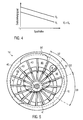
- Fig. 1 shows schematically a vacuum filler 100 according to the present invention.
- the vacuum filler 100 comprises a vacuum hopper 1 composed of a hopper 33 and a lid 2.
- the funnel 33 and the cover 2 are connected to each other via a seal 34, here for example a sealing ring, vacuum-tight.
- the vacuum hopper 1 comprises an inlet 7 for supplying a pasty mass from a reservoir, not shown, via the feed tube 8.
- the hopper 1 further comprises at the lower end, ie at the opposite end of the lid 2 an outlet 13 for the pasty mass.
- the pasty mass, which is located in the funnel is here promoted by a circulating feeder curve 10 towards the center.
- the feeder curve 10 here has a scraper 11.
- the feed cam is rotatably mounted in a known manner in the bearing 12 about the central axis D and is rotated by means of a drive, not shown, in a known manner about the axis D.
- the scraper 11 comes to lie on the inner wall of the funnel 1.
- a conveyor is arranged, which promotes the pasty mass from the vacuum hopper 1 in a filling tube 15. About the filling tube 15 is then pasty mass, such as the sausage meat, pushed into designated sausage casings in a known manner.
- a negative pressure is generated by means of a vacuum pump 23, which is indicated here only schematically. This is done z. B. via a separate vacuum port 60.
- a vacuum pump 23 which is indicated here only schematically.
- the air content is also crucial for the cut and bite of the finished product.
- the negative pressure in the vacuum hopper 1 further brings with it the advantage that the pasty mass to be filled is pressed or pulled out of the storage container by the normal pressure prevailing there into the closed vacuum hopper 1.
- the feed of the vacuum hopper can also be assisted with an additional pump or under pressure.
- a negative pressure can also be generated by means of a vacuum pump 23 to the pasty mass, d. H. the sausage meat still additional air and thus to withdraw oxygen.
- the absolute pressure in the conveyor is less than or equal to the pressure in the vacuum hopper, so that is pressed by the negative pressure in the conveyor 14, the pasty mass from the vacuum hopper in the conveyor chambers.
- FIG. Fig. 5 shows a well-known vane pump, as also closer in the EP 1040758 B1 or in the DE 4227621 A1 is described.
- the vane pump consists of a pump housing 40 and an eccentric arranged therein, in rotation displaceable rotor with a pump shaft 41.
- the pump housing 40 has a sausage meat inlet 50 and a sausage meat outlet 51, between which a compression sector 52 and a Dosieresektor 53 can be realized.
- the inlet 50 is connected to the outlet 13 of the vacuum hopper 1.
- In the compression sector 52 changes z.
- Example in this embodiment, the inner wall 42 their distance from the pump shaft 41, so that the measured upon rotation of the rotor about the pump shaft 41 in the direction A of the compression space length of the wings 43 shortened because the wings on the compression space side in the direction of the shaft 41 out be moved.
- the volume of the chamber 8a in the compression sector 52 is reduced.
- the chamber volume remains constant upon rotation of the rotor about the shaft 41, so that a defined metering volume is formed.
- the outlet sector 59 is the respective vane with a vane outlet 51 in conjunction through which the pasty mass z. B. is pushed into the filling tube 15.
- the present invention makes it possible to influence or regulate the degree of evacuation of the mass flowing into the vacuum hopper 1.
- the inlet valve 3 is provided at the inlet 7.
- the valve 3 comprises the valve seat 9, which is located at the end of the feed tube 8.
- the inlet 7 is here in the upper region, ie provided in the upper third of the vacuum hopper 1.
- the inlet pipe 8 protrudes into the vacuum hopper, wherein in this embodiment, the open end of the inlet pipe 8 is turned upwards.
- a corresponding seal, sealing ring, etc. may be arranged at the upper end of the feed tube 8.
- the inlet valve 3 further comprises the baffle plate 5, which is opposite to the valve seat 9 of the feed tube 8.
- the baffle plate 5 is connected via the rod 17 with a drive 4, which can move the baffle plate 5 in the direction of arrow F up and down along the central axis M of the inlet valve 3.
- the central axis M of the valve 3 extends substantially parallel to the central axis D of the vacuum hopper 1.
- the drive 4 comprises a motor, for example a stepper motor, which is controlled by a control or regulating device 22, and the position the baffle plate 5 sets.
- the valve geometry is preferably designed so that the inlet gap S has the largest possible length, d. H. that the inlet pipe has the largest possible diameter, or the largest possible circumference.
- the entrance slit S has a circular or oval or elliptical cross-sectional geometry, but also other cross-sectional geometries are conceivable. This results in a relatively thin mass cross section in the inflow region. This means that all trapped air fractions are close to the surface and can therefore be easily torn open and sucked off.
- the amount of evacuation can be influenced by the height h of the inlet gap S.
- the baffle plate 5 has a larger diameter than the feed tube 8 in the region of the valve seat 9, so that the end regions of the baffle plate 5 project beyond the valve seat 9.
- the baffle plate 5 is formed such that it is the incoming sausage meat down, d. H. to the outlet 13 of the vacuum hopper 1 deflects. Due to the special shape of the baffle plate 5, the fill level can be better controlled, especially in the case of low-viscosity fillers, since the sausage meat on entry into the funnel does not splash so much against the lid and the funnel wall. For example, as is apparent from FIGS.
- the baffle plate 5 on the side directed toward the valve seat has a recess 6 which, at least in the outer region of the inlet gap S, has a section A inclined obliquely outwards and downwards from the central axis M. is. This inclined section directs the mass down.
- the inclined portion A should be provided at least in the area adjoining the inlet gap (between the underside of the baffle plate and the valve seat 9) from outside, but, as shown in FIG. 1, need not extend all the way to the outer edge of the baffle plate 5 extend out.
- Fig. 2 shows a plan view of the baffle plate 5 shown in Fig. 1, wherein clearly the recess 6 can be seen, which here extends annularly around the central axis M of the valve.
- the shape is not limited to the shape of the recess 6 shown in FIG. It can, for example, also a, as shown in Fig. 3, concave shaped recess 6 are formed in the baffle plate 5, which is substantially rotationally symmetrical to the central axis M.
- the recess 6 has a section A, here at approximately 130 ° with respect to the inlet direction E, d. H. is inclined to the central axis M, and so the inflowing mass deflects downwards.
- the section A should be inclined at an angle of approximately 100-180 ° with respect to the center axis M and the inlet direction E, respectively, in order to realize a corresponding deflection.
- the height h of the inlet gap S is controlled so that, depending on various parameters, the inlet gap S is kept as small as required for level control and at the same time as small as possible for controlling the evacuation.
- a minimum gap control is at least one of the following group in question: compressibility or air content of the pasty mass in front of the inlet valve, compressibility or air content of the pasty mass after the outlet 13, z. B. at the outlet of the conveyor 14, filling capacity of the pasty mass of the reservoir into the vacuum hopper 1, piece size of deposits of pasty mass, pressure difference before and after the inlet valve 3, level, viscosity of the pasty mass, temperature of the mass, etc.
- corresponding pressure sensors 18 may be provided in front of the inlet valve 3 or 19 in the vacuum hopper 1.
- a corresponding level sensor 21 may be provided in the vacuum hopper 1.
- a level sensor for example, an ultrasonic sensor, a mechanical level sensor or a capacitive or optical sensor can be used, which either indicates the exact level or indicates whether the level is within a permissible range.
- a device 16 for measuring the compressibility can be provided, for example, in the conveyor 14.
- a device for measuring the compressibility 62, 61 may also be provided in front of the inlet valve 3 or in the funnel (1).
- 16 represents a device for measuring the compressibility.
- the function of a compressibility sensor is exemplified in Figs EP 1040758 B1 explained in more detail.
- the device 16 thus comprises a pressure sensor which detects the pressure change in the variable-volume chamber, wherein the exact volume change is also detected, from which the compressibility can be calculated.
- other known devices for measuring compressibility may be used.
- the measuring devices listed above such as the devices for measuring the compressibility 16, the pressure sensors 18, 19, the level gauge 21 may be connected to the control device 22, which in turn regulates the setting of the inlet gap S.
- the gap height h of the inlet valve 3 can be controlled depending on different parameters so that both the level and the evacuation of the pasty mass can be controlled.
- the control is carried out by a minimum gap control, wherein the inlet gap S is kept only as high as required for level control and at the same time as small as possible to control the evacuation.
- Fig. 4 shows schematically the relationship between evacuation degree and gap height h.
- the degree of evacuation is also dependent on the delivery rate and thus on the conveying speed V 1 ; V 2 of the mass in the funnel. Usually, the evacuation level is higher at low speed V 2 than at higher speed V 1 .
- the degree of evacuation also depends on the negative pressure in the vacuum hopper and possibly on the nature of the pasty mass, ie for example on the deposits in the pasty mass.
- the gap height h of the inlet gap S is regulated as a function of the air content, ie the compressibility of the pasty mass (for example in front of the inlet valve 3 and / or downstream of the outlet 13) and, moreover, also as a function of fill level parameters how, for example, filling capacity of the pasty mass in the vacuum hopper 1 and / or level in the vacuum hopper 1 is controlled, this can be done by a closed loop, the control variables such as the air content of the pasty mass and the level and the actuator, the inlet valve 3. So a certain proportion of air, for example 0.5 to 10%, can be adjusted.
- the entrance slit S is however also regulated in the sense of a minimum gap control, that the level is in a certain Medstandsssoll Symposium.
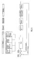
- FIG. 6 shows a block diagram for an embodiment of a control loop according to the present invention
- the regulation of the entry gap S will be explained in more detail.
- control variables are the level and evacuation level, i. Air content or compressibility of the pasty mass
- the actuator is the inlet valve.
- the controlled system is the evacuation of the sausage meat, or the filling of the funnel.
- Control elements for the closed control are the compressibility sensor and the level gauge. In this particular example, the compressibility in the outlet of the conveyor 14 is measured to control.
- the control device, d. H. the controller compares actual and setpoint values of the respective control variables and adjusts the entry gap height h as a function of the actual setpoint comparison in order to set a certain air proportion per unit volume in the pasty mass and also to keep the fill level correct.
- control can influence other parameters, such as pressure before the inlet valve or pressure after the inlet valve, compressibility of the mass in front of the inlet valve, compressibility of the mass in the hopper, viscosity of the mass, temperature of the mass, piece sizes of deposits, etc.
- the aforementioned parameters can either be determined via corresponding measuring devices as described above, the values of which are then supplied to the controller or else entered.
- the control device 22 is connected to an input device, in which z. B. the different setpoints for air content or compressibility, filling capacity, level, pressure in the vacuum hopper 1 and pressure in front of the inlet valve 3, pressure in the outlet and properties such. B. temperature and nature of pasty mass can be entered.
- the block diagram shown in Figure 6 shows only one example of a control according to the present invention and is in no way limited thereto. It is only essential in the present invention that the inlet valve is the actuator for controlling the degree of evacuation of the pasty mass, ie. H. is for a certain proportion of air in the pasty mass or the corresponding compressibility.
Landscapes
- Engineering & Computer Science (AREA)
- General Engineering & Computer Science (AREA)
- Life Sciences & Earth Sciences (AREA)
- Mechanical Engineering (AREA)
- Food Science & Technology (AREA)
- Zoology (AREA)
- Wood Science & Technology (AREA)
- Processing Of Meat And Fish (AREA)
- Supply Of Fluid Materials To The Packaging Location (AREA)
- Meat, Egg Or Seafood Products (AREA)
- Control And Other Processes For Unpacking Of Materials (AREA)
- General Preparation And Processing Of Foods (AREA)
- Road Paving Machines (AREA)
- Preparation Of Fruits And Vegetables (AREA)
Priority Applications (4)
| Application Number | Priority Date | Filing Date | Title |
|---|---|---|---|
| EP07006713.7A EP1836896B1 (fr) | 2006-03-09 | 2006-03-09 | Dispositif et procédé destinés à la régulation du niveau de remplissage et à l'évacuation régulée de masses pâteuses |
| PL07006713T PL1836896T3 (pl) | 2006-03-09 | 2006-03-09 | Urządzenie i sposób regulacji poziomu wypełnienia i regulowanej ewakuacji pastowatych mas |
| ES07006713.7T ES2605940T3 (es) | 2006-03-09 | 2006-03-09 | Dispositivo y procedimiento para la regulación del nivel de llenado y para la exposición regulada a vacío de masas pastosas |
| DK07006713.7T DK1836896T3 (en) | 2006-03-09 | 2006-03-09 | Device and method for fullness control and for controlled evacuation of pastous masses |
Applications Claiming Priority (2)
| Application Number | Priority Date | Filing Date | Title |
|---|---|---|---|
| EP07006713.7A EP1836896B1 (fr) | 2006-03-09 | 2006-03-09 | Dispositif et procédé destinés à la régulation du niveau de remplissage et à l'évacuation régulée de masses pâteuses |
| EP06004867A EP1832176B1 (fr) | 2006-03-09 | 2006-03-09 | Dispositif de régulation du remplissage et d'évacuation réglée d'un produit pâteux |
Related Parent Applications (1)
| Application Number | Title | Priority Date | Filing Date |
|---|---|---|---|
| EP06004867A Division EP1832176B1 (fr) | 2006-03-09 | 2006-03-09 | Dispositif de régulation du remplissage et d'évacuation réglée d'un produit pâteux |
Publications (2)
| Publication Number | Publication Date |
|---|---|
| EP1836896A1 true EP1836896A1 (fr) | 2007-09-26 |
| EP1836896B1 EP1836896B1 (fr) | 2016-09-14 |
Family
ID=36688122
Family Applications (2)
| Application Number | Title | Priority Date | Filing Date |
|---|---|---|---|
| EP07006713.7A Expired - Lifetime EP1836896B1 (fr) | 2006-03-09 | 2006-03-09 | Dispositif et procédé destinés à la régulation du niveau de remplissage et à l'évacuation régulée de masses pâteuses |
| EP06004867A Expired - Lifetime EP1832176B1 (fr) | 2006-03-09 | 2006-03-09 | Dispositif de régulation du remplissage et d'évacuation réglée d'un produit pâteux |
Family Applications After (1)
| Application Number | Title | Priority Date | Filing Date |
|---|---|---|---|
| EP06004867A Expired - Lifetime EP1832176B1 (fr) | 2006-03-09 | 2006-03-09 | Dispositif de régulation du remplissage et d'évacuation réglée d'un produit pâteux |
Country Status (9)
| Country | Link |
|---|---|
| US (1) | US7597612B2 (fr) |
| EP (2) | EP1836896B1 (fr) |
| JP (1) | JP4568737B2 (fr) |
| CN (1) | CN101258865B (fr) |
| AT (1) | ATE415095T1 (fr) |
| DE (1) | DE502006002192D1 (fr) |
| DK (2) | DK1832176T3 (fr) |
| ES (2) | ES2605940T3 (fr) |
| PL (2) | PL1836896T3 (fr) |
Cited By (1)
| Publication number | Priority date | Publication date | Assignee | Title |
|---|---|---|---|---|
| EP3150072A1 (fr) * | 2015-09-29 | 2017-04-05 | Albert Handtmann Maschinenfabrik GmbH & Co. KG | Machine de remplissage et procédé de mesure de niveau de remplissage à l'aide d'un capteur radar en particulier pour la fabrication de saucisses |
Families Citing this family (17)
| Publication number | Priority date | Publication date | Assignee | Title |
|---|---|---|---|---|
| EP1836896B1 (fr) | 2006-03-09 | 2016-09-14 | Albert Handtmann Maschinenfabrik GmbH & Co. KG | Dispositif et procédé destinés à la régulation du niveau de remplissage et à l'évacuation régulée de masses pâteuses |
| DE202008016702U1 (de) * | 2008-12-18 | 2010-06-02 | Vemag Maschinenbau Gmbh | Vorrichtung zum Abfüllen bzw. Bearbeiten von pastösen Massen insbesondere Wurstbrät |
| DE202009002115U1 (de) | 2009-02-13 | 2010-07-15 | Vemag Maschinenbau Gmbh | Mischvorrichtung für Lebensmittel-Massen wie Wurstbrät sowie Füllmaschine |
| IT1395033B1 (it) * | 2009-08-06 | 2012-09-05 | Minerva Di Chiodini Mario S R L | Dispositivo a tramoggia per alimenti |
| EP2377405B1 (fr) * | 2010-04-13 | 2013-06-05 | Albert Handtmann Maschinenfabrik GmbH & Co. KG | Dispositif et procédé de fabrication et de remplissage de chair à saucisse, notamment d'une émulsion |
| ES2427417T3 (es) * | 2011-05-20 | 2013-10-30 | Albert Handtmann Maschinenfabrik Gmbh & Co. Kg | Regulador de vacío en una llenadora al vacío sin aporte de aire exterior |
| NL2006958C2 (en) | 2011-06-17 | 2012-12-18 | Marel Townsend Further Proc Bv | Processing a mass of pumpable foodstuff material. |
| CN102700763A (zh) * | 2012-05-24 | 2012-10-03 | 江南大学 | 真空定量灌装机的送料装置 |
| EP3081813B1 (fr) * | 2015-04-16 | 2017-09-20 | Albert Handtmann Maschinenfabrik GmbH & Co. KG | Machine de remplissage et procédé de remplissage d'une substance pâteuse |
| PL3081088T3 (pl) * | 2015-04-16 | 2019-06-28 | Albert Handtmann Maschinenfabrik Gmbh & Co. Kg | Nadziewarka i sposób kontrolowania stanu zanieczyszczenia w układzie próżniowym nadziewarki |
| DE102016216851A1 (de) * | 2016-09-06 | 2018-03-08 | Albert Handtmann Maschinenfabrik Gmbh & Co. Kg | Verfahren und Füllmaschine zum Abfüllen eines Lebensmittels |
| CN108082768B (zh) * | 2017-11-21 | 2019-05-21 | 宁波大发化纤有限公司 | 智能型料仓及其控制方法 |
| CN110605046A (zh) * | 2019-10-24 | 2019-12-24 | 宿州市恒元食品机械有限公司 | 一种馅料输送装置 |
| EP4129069A1 (fr) * | 2021-08-06 | 2023-02-08 | Albert Handtmann Maschinenfabrik GmbH & Co. KG | Système de remplissage et de découpe pour denrées alimentaires et procédé de réglage de la vitesse de rotation d'une courbe d'alimentation/de mélange associée et/ou d'un dispositif de contre-maintien |
| EP4541198A1 (fr) * | 2023-10-20 | 2025-04-23 | Albert Handtmann Maschinenfabrik GmbH & Co. KG | Machine de remplissage et procédé de remplissage de produits alimentaires et d'ajustement de la pression dans une zone de compression d'une pompe |
| CN118355936A (zh) * | 2024-05-15 | 2024-07-19 | 深圳市金口味食品有限公司 | 一种香肠的制备设备及方法 |
| KR102916764B1 (ko) * | 2024-07-03 | 2026-01-23 | (주)하이젠텍 | 절단 수율 개선을 위한 센서 불량 진단 시스템을 갖춘 누에고치 절단 장치 |
Citations (5)
| Publication number | Priority date | Publication date | Assignee | Title |
|---|---|---|---|---|
| US3166786A (en) | 1963-02-21 | 1965-01-26 | John E Thompson | Sausage stuffeer |
| GB1380082A (en) * | 1971-02-25 | 1975-01-08 | Matthews Co Worcester Ltd K R | Feed hoppers |
| US4427040A (en) * | 1979-03-12 | 1984-01-24 | Taylor Murland L | Reverse flow pop-off air control |
| DE4417906A1 (de) * | 1994-05-21 | 1995-11-23 | Vemag Maschinenbau Gmbh | Verfahren und Vorrichtung zum Fördern pastöser Masse |
| EP1502509A1 (fr) | 2002-04-17 | 2005-02-02 | Metalquimia, S.A. | Machine a fabriquer et decouper des saucisses a tremie inclinable |
Family Cites Families (18)
| Publication number | Priority date | Publication date | Assignee | Title |
|---|---|---|---|---|
| DE459031C (de) | 1930-09-01 | Paul Schubert | Fleischmisch- und Ballendrueckmaschine fuer die Wurstherstellung | |
| GB998572A (en) * | 1961-03-21 | 1965-07-14 | Nicholson Terence Peter | Improvements relating to stop valves |
| US3742556A (en) * | 1971-07-02 | 1973-07-03 | Townsend Engineering Co | Meat emulsion pump |
| JPS5811185Y2 (ja) * | 1979-01-23 | 1983-03-02 | 株式会社日阪製作所 | 練製品の連続脱気装置 |
| DE3513297A1 (de) * | 1985-04-13 | 1986-10-16 | Klein, Schanzlin & Becker Ag, 6710 Frankenthal | Absperrventil mit weichdichtendem ventilkegel |
| DE3617495C2 (de) | 1986-05-24 | 1996-04-11 | Schnell Maschfab Karl | Fördervorrichtung insbesondere für steife Massen |
| ES2015660A6 (es) * | 1989-05-19 | 1990-09-01 | Metalquimia Sa | Procedimiento para dosificacion y embutido de masas carnicas, al vacio y maquina para su realizacion. |
| JPH0316656A (ja) * | 1989-06-15 | 1991-01-24 | Masuko Sangyo Co Ltd | 真空又は嫌気性ガス雰囲気中の摩砕方法及びその装置 |
| JP2521604B2 (ja) * | 1991-11-19 | 1996-08-07 | 財団法人未来農業国際研究財団 | 高落差用自動定量分水装置 |
| DK174039B1 (da) * | 1992-05-14 | 2002-05-06 | Cfs Slagelse As | Sneglpumpe til tyktflydende og/eller klumpholdigemedier, f.eks. kød. |
| DE4227621A1 (de) | 1992-08-20 | 1994-02-24 | Handtmann Albert Maschf | Verfahren und Vorrichtung zum portionsweisen Unterteilen einer pastösen und kompressiblen Masse, insbesondere eines Wurstbräts mit Hilfe einer Flügelzellenpumpe |
| ES2154962B1 (es) * | 1997-12-05 | 2001-12-01 | Metalquimia Sa | Maquina embutidora-dosificadora de materias alimenticias pastosas. |
| DE29808373U1 (de) * | 1998-05-08 | 1999-09-16 | Vemag Maschinen- Und Anlagenbau Gmbh, 27283 Verden | Füllmaschine für Wurstbrät o.dgl. mit einem abklappbaren Vorratsbehälter |
| DE19914499C2 (de) | 1999-03-30 | 2001-12-20 | Handtmann Albert Maschf | Fördervorrichtung für pastöse Massen und Verfahren zur Bestimmung deren Luftinhaltes |
| US6321642B1 (en) * | 2001-07-10 | 2001-11-27 | Robert Ou-Young | Filling mechanism for food stuffing |
| US6685549B2 (en) * | 2002-05-29 | 2004-02-03 | David F. Henry | Method and device for increasing the shelf life of an oxygen sensitive product |
| US6939215B2 (en) * | 2003-01-17 | 2005-09-06 | Kraft Foods Holdings, Inc. | Method for reducing viscosity of mechanically separated meats and ground meats |
| EP1836896B1 (fr) | 2006-03-09 | 2016-09-14 | Albert Handtmann Maschinenfabrik GmbH & Co. KG | Dispositif et procédé destinés à la régulation du niveau de remplissage et à l'évacuation régulée de masses pâteuses |
-
2006
- 2006-03-09 EP EP07006713.7A patent/EP1836896B1/fr not_active Expired - Lifetime
- 2006-03-09 PL PL07006713T patent/PL1836896T3/pl unknown
- 2006-03-09 ES ES07006713.7T patent/ES2605940T3/es not_active Expired - Lifetime
- 2006-03-09 PL PL06004867T patent/PL1832176T3/pl unknown
- 2006-03-09 AT AT06004867T patent/ATE415095T1/de active
- 2006-03-09 EP EP06004867A patent/EP1832176B1/fr not_active Expired - Lifetime
- 2006-03-09 DK DK06004867T patent/DK1832176T3/da active
- 2006-03-09 DE DE502006002192T patent/DE502006002192D1/de not_active Expired - Lifetime
- 2006-03-09 DK DK07006713.7T patent/DK1836896T3/en active
- 2006-03-09 ES ES06004867T patent/ES2314767T3/es not_active Expired - Lifetime
-
2007
- 2007-02-23 US US11/710,113 patent/US7597612B2/en active Active
- 2007-02-28 JP JP2007049876A patent/JP4568737B2/ja active Active
- 2007-03-09 CN CN2007100798007A patent/CN101258865B/zh active Active
Patent Citations (5)
| Publication number | Priority date | Publication date | Assignee | Title |
|---|---|---|---|---|
| US3166786A (en) | 1963-02-21 | 1965-01-26 | John E Thompson | Sausage stuffeer |
| GB1380082A (en) * | 1971-02-25 | 1975-01-08 | Matthews Co Worcester Ltd K R | Feed hoppers |
| US4427040A (en) * | 1979-03-12 | 1984-01-24 | Taylor Murland L | Reverse flow pop-off air control |
| DE4417906A1 (de) * | 1994-05-21 | 1995-11-23 | Vemag Maschinenbau Gmbh | Verfahren und Vorrichtung zum Fördern pastöser Masse |
| EP1502509A1 (fr) | 2002-04-17 | 2005-02-02 | Metalquimia, S.A. | Machine a fabriquer et decouper des saucisses a tremie inclinable |
Cited By (2)
| Publication number | Priority date | Publication date | Assignee | Title |
|---|---|---|---|---|
| EP3150072A1 (fr) * | 2015-09-29 | 2017-04-05 | Albert Handtmann Maschinenfabrik GmbH & Co. KG | Machine de remplissage et procédé de mesure de niveau de remplissage à l'aide d'un capteur radar en particulier pour la fabrication de saucisses |
| US10921173B2 (en) | 2015-09-29 | 2021-02-16 | Albert Handtmann Maschinenfabrik Gmbh & Co. Kg | Filling machine and method for the filling level measurement, in particular for the sausage production |
Also Published As
| Publication number | Publication date |
|---|---|
| CN101258865A (zh) | 2008-09-10 |
| DK1836896T3 (en) | 2016-12-19 |
| EP1836896B1 (fr) | 2016-09-14 |
| EP1832176B1 (fr) | 2008-11-26 |
| US20070254570A1 (en) | 2007-11-01 |
| JP4568737B2 (ja) | 2010-10-27 |
| EP1832176A1 (fr) | 2007-09-12 |
| PL1836896T3 (pl) | 2017-03-31 |
| ES2605940T3 (es) | 2017-03-17 |
| ES2314767T3 (es) | 2009-03-16 |
| PL1832176T3 (pl) | 2009-07-31 |
| DK1832176T3 (da) | 2009-03-16 |
| ATE415095T1 (de) | 2008-12-15 |
| DE502006002192D1 (de) | 2009-01-08 |
| US7597612B2 (en) | 2009-10-06 |
| CN101258865B (zh) | 2010-12-29 |
| JP2007259849A (ja) | 2007-10-11 |
Similar Documents
| Publication | Publication Date | Title |
|---|---|---|
| EP1836896B1 (fr) | Dispositif et procédé destinés à la régulation du niveau de remplissage et à l'évacuation régulée de masses pâteuses | |
| EP1977877B1 (fr) | Extrudeuse | |
| DD297303A5 (de) | Verfahren und vorrichtung zur quatitativen teilung von brotteig | |
| DE2209355A1 (de) | Spritzpresse | |
| EP2946702A1 (fr) | Machine à café pour capsules | |
| EP3605034B1 (fr) | Dispositif d'entrée pour un moulin à cylindres, moulin à cylindres doté d'un tel dispositif d'entrée, procédé de détermination du niveau de remplissage de produit de broyage d'un réservoir d'alimentation d'un moulin à cylindres | |
| EP2525098B1 (fr) | Réglage du sous vide dans un remplisseur à sous vide sans entrée d'air extérieur | |
| EP2710896B1 (fr) | Dispositif d'acheminement de produits alimentaires et procédé d'acheminement d'un produit alimentaire | |
| EP1829451A1 (fr) | Dispositif et méthode pour amener du matériau pateux à une machine de mise en buyau de saucisses | |
| EP3587285B1 (fr) | Procédé de détermination du débit volumétrique et du degré de remplissage sur une machine d'emballage | |
| EP2220950A2 (fr) | Cartouche de vidage et procédé de vidage de combles remplis de produits en forme de tiges, notamment combles de puits ainsi que dispositif de réunion de flux de matière, notamment pour une cartouche de vidage | |
| EP2896571A1 (fr) | Dispositif de dosage et procédé de dosage | |
| EP3868211B1 (fr) | Dispositif et procédé de fabrication de produits coextrudés à épaisseur variable de la matière d'enveloppe | |
| EP3832179B1 (fr) | Soupape de dosage et machine de remplissage permettant de doser des denrées alimentaires | |
| WO2014117864A1 (fr) | Dispositif d'alimentation de matériau en morceaux dans une presse à briqueter | |
| EP1048213A2 (fr) | Machine de bourrage de saucisses | |
| DE102017207162A1 (de) | Vorrichtung zum Komprimieren eines Produkts | |
| EP1040758B1 (fr) | Dispositif de transport pour matières pâteuses et procédé pour déterminer la quantité d'air | |
| WO2007045595A1 (fr) | Separateur a vidage automatique et procede pour le faire fonctionner | |
| AT513798A1 (de) | Vorrichtung und Verfahren zur dosierten, formgebenden Ausgabe von Massenkörpern aus pumpfähigen Massen | |
| EP2468106B1 (fr) | Dispositif et procédé de répartition d'air résiduel dans des masses pâteuses, notamment pour la fabrication de saucisses | |
| EP1362787B1 (fr) | Procédé et appareil pour remplir des sacs muni de moyens d'extraction d'air | |
| EP3728051A1 (fr) | Machine d'emballage et procédé pour le remplissage de produits en vrac dans des emballages | |
| EP2532244B1 (fr) | Procédé et dispositif de réglage de la compression dans une pompe à cellules battantes | |
| EP3207805B1 (fr) | Remplissage de produits alimentaires avec composante solide et liquide |
Legal Events
| Date | Code | Title | Description |
|---|---|---|---|
| PUAI | Public reference made under article 153(3) epc to a published international application that has entered the european phase |
Free format text: ORIGINAL CODE: 0009012 |
|
| 17P | Request for examination filed |
Effective date: 20070809 |
|
| AC | Divisional application: reference to earlier application |
Ref document number: 1832176 Country of ref document: EP Kind code of ref document: P |
|
| AK | Designated contracting states |
Kind code of ref document: A1 Designated state(s): AT BE BG CH CY CZ DE DK EE ES FI FR GB GR HU IE IS IT LI LT LU LV MC NL PL PT RO SE SI SK TR |
|
| AX | Request for extension of the european patent |
Extension state: AL BA HR MK YU |
|
| AKX | Designation fees paid |
Designated state(s): AT BE BG CH CY CZ DE DK EE ES FI FR GB GR HU IE IS IT LI LT LU LV MC NL PL PT RO SE SI SK TR |
|
| 17Q | First examination report despatched |
Effective date: 20090109 |
|
| GRAP | Despatch of communication of intention to grant a patent |
Free format text: ORIGINAL CODE: EPIDOSNIGR1 |
|
| INTG | Intention to grant announced |
Effective date: 20160414 |
|
| GRAS | Grant fee paid |
Free format text: ORIGINAL CODE: EPIDOSNIGR3 |
|
| GRAA | (expected) grant |
Free format text: ORIGINAL CODE: 0009210 |
|
| AC | Divisional application: reference to earlier application |
Ref document number: 1832176 Country of ref document: EP Kind code of ref document: P |
|
| AK | Designated contracting states |
Kind code of ref document: B1 Designated state(s): AT BE BG CH CY CZ DE DK EE ES FI FR GB GR HU IE IS IT LI LT LU LV MC NL PL PT RO SE SI SK TR |
|
| REG | Reference to a national code |
Ref country code: GB Ref legal event code: FG4D Free format text: NOT ENGLISH |
|
| REG | Reference to a national code |
Ref country code: CH Ref legal event code: EP |
|
| REG | Reference to a national code |
Ref country code: CH Ref legal event code: NV Representative=s name: PATENTANWALTSBUERO JEAN HUNZIKER AG, CH |
|
| REG | Reference to a national code |
Ref country code: IE Ref legal event code: FG4D Free format text: LANGUAGE OF EP DOCUMENT: GERMAN |
|
| REG | Reference to a national code |
Ref country code: AT Ref legal event code: REF Ref document number: 827897 Country of ref document: AT Kind code of ref document: T Effective date: 20161015 |
|
| REG | Reference to a national code |
Ref country code: DE Ref legal event code: R096 Ref document number: 502006015162 Country of ref document: DE |
|
| REG | Reference to a national code |
Ref country code: DK Ref legal event code: T3 Effective date: 20161216 |
|
| REG | Reference to a national code |
Ref country code: NL Ref legal event code: FP |
|
| REG | Reference to a national code |
Ref country code: LT Ref legal event code: MG4D |
|
| PG25 | Lapsed in a contracting state [announced via postgrant information from national office to epo] |
Ref country code: FI Free format text: LAPSE BECAUSE OF FAILURE TO SUBMIT A TRANSLATION OF THE DESCRIPTION OR TO PAY THE FEE WITHIN THE PRESCRIBED TIME-LIMIT Effective date: 20160914 Ref country code: LT Free format text: LAPSE BECAUSE OF FAILURE TO SUBMIT A TRANSLATION OF THE DESCRIPTION OR TO PAY THE FEE WITHIN THE PRESCRIBED TIME-LIMIT Effective date: 20160914 |
|
| PG25 | Lapsed in a contracting state [announced via postgrant information from national office to epo] |
Ref country code: SE Free format text: LAPSE BECAUSE OF FAILURE TO SUBMIT A TRANSLATION OF THE DESCRIPTION OR TO PAY THE FEE WITHIN THE PRESCRIBED TIME-LIMIT Effective date: 20160914 Ref country code: GR Free format text: LAPSE BECAUSE OF FAILURE TO SUBMIT A TRANSLATION OF THE DESCRIPTION OR TO PAY THE FEE WITHIN THE PRESCRIBED TIME-LIMIT Effective date: 20161215 Ref country code: LV Free format text: LAPSE BECAUSE OF FAILURE TO SUBMIT A TRANSLATION OF THE DESCRIPTION OR TO PAY THE FEE WITHIN THE PRESCRIBED TIME-LIMIT Effective date: 20160914 |
|
| REG | Reference to a national code |
Ref country code: ES Ref legal event code: FG2A Ref document number: 2605940 Country of ref document: ES Kind code of ref document: T3 Effective date: 20170317 |
|
| REG | Reference to a national code |
Ref country code: FR Ref legal event code: PLFP Year of fee payment: 12 |
|
| PG25 | Lapsed in a contracting state [announced via postgrant information from national office to epo] |
Ref country code: EE Free format text: LAPSE BECAUSE OF FAILURE TO SUBMIT A TRANSLATION OF THE DESCRIPTION OR TO PAY THE FEE WITHIN THE PRESCRIBED TIME-LIMIT Effective date: 20160914 Ref country code: RO Free format text: LAPSE BECAUSE OF FAILURE TO SUBMIT A TRANSLATION OF THE DESCRIPTION OR TO PAY THE FEE WITHIN THE PRESCRIBED TIME-LIMIT Effective date: 20160914 |
|
| PG25 | Lapsed in a contracting state [announced via postgrant information from national office to epo] |
Ref country code: SK Free format text: LAPSE BECAUSE OF FAILURE TO SUBMIT A TRANSLATION OF THE DESCRIPTION OR TO PAY THE FEE WITHIN THE PRESCRIBED TIME-LIMIT Effective date: 20160914 Ref country code: CZ Free format text: LAPSE BECAUSE OF FAILURE TO SUBMIT A TRANSLATION OF THE DESCRIPTION OR TO PAY THE FEE WITHIN THE PRESCRIBED TIME-LIMIT Effective date: 20160914 Ref country code: BG Free format text: LAPSE BECAUSE OF FAILURE TO SUBMIT A TRANSLATION OF THE DESCRIPTION OR TO PAY THE FEE WITHIN THE PRESCRIBED TIME-LIMIT Effective date: 20161214 Ref country code: PT Free format text: LAPSE BECAUSE OF FAILURE TO SUBMIT A TRANSLATION OF THE DESCRIPTION OR TO PAY THE FEE WITHIN THE PRESCRIBED TIME-LIMIT Effective date: 20170116 Ref country code: IS Free format text: LAPSE BECAUSE OF FAILURE TO SUBMIT A TRANSLATION OF THE DESCRIPTION OR TO PAY THE FEE WITHIN THE PRESCRIBED TIME-LIMIT Effective date: 20170114 |
|
| REG | Reference to a national code |
Ref country code: DE Ref legal event code: R097 Ref document number: 502006015162 Country of ref document: DE |
|
| PLBE | No opposition filed within time limit |
Free format text: ORIGINAL CODE: 0009261 |
|
| STAA | Information on the status of an ep patent application or granted ep patent |
Free format text: STATUS: NO OPPOSITION FILED WITHIN TIME LIMIT |
|
| 26N | No opposition filed |
Effective date: 20170615 |
|
| GBPC | Gb: european patent ceased through non-payment of renewal fee |
Effective date: 20170309 |
|
| PG25 | Lapsed in a contracting state [announced via postgrant information from national office to epo] |
Ref country code: MC Free format text: LAPSE BECAUSE OF FAILURE TO SUBMIT A TRANSLATION OF THE DESCRIPTION OR TO PAY THE FEE WITHIN THE PRESCRIBED TIME-LIMIT Effective date: 20160914 Ref country code: SI Free format text: LAPSE BECAUSE OF FAILURE TO SUBMIT A TRANSLATION OF THE DESCRIPTION OR TO PAY THE FEE WITHIN THE PRESCRIBED TIME-LIMIT Effective date: 20160914 |
|
| REG | Reference to a national code |
Ref country code: IE Ref legal event code: MM4A |
|
| PG25 | Lapsed in a contracting state [announced via postgrant information from national office to epo] |
Ref country code: LU Free format text: LAPSE BECAUSE OF NON-PAYMENT OF DUE FEES Effective date: 20170309 |
|
| PG25 | Lapsed in a contracting state [announced via postgrant information from national office to epo] |
Ref country code: GB Free format text: LAPSE BECAUSE OF NON-PAYMENT OF DUE FEES Effective date: 20170309 Ref country code: IE Free format text: LAPSE BECAUSE OF NON-PAYMENT OF DUE FEES Effective date: 20170309 |
|
| REG | Reference to a national code |
Ref country code: BE Ref legal event code: MM Effective date: 20170331 |
|
| REG | Reference to a national code |
Ref country code: FR Ref legal event code: PLFP Year of fee payment: 13 |
|
| PG25 | Lapsed in a contracting state [announced via postgrant information from national office to epo] |
Ref country code: BE Free format text: LAPSE BECAUSE OF NON-PAYMENT OF DUE FEES Effective date: 20170331 |
|
| PG25 | Lapsed in a contracting state [announced via postgrant information from national office to epo] |
Ref country code: HU Free format text: LAPSE BECAUSE OF FAILURE TO SUBMIT A TRANSLATION OF THE DESCRIPTION OR TO PAY THE FEE WITHIN THE PRESCRIBED TIME-LIMIT; INVALID AB INITIO Effective date: 20060309 |
|
| PG25 | Lapsed in a contracting state [announced via postgrant information from national office to epo] |
Ref country code: CY Free format text: LAPSE BECAUSE OF NON-PAYMENT OF DUE FEES Effective date: 20160914 |
|
| PG25 | Lapsed in a contracting state [announced via postgrant information from national office to epo] |
Ref country code: TR Free format text: LAPSE BECAUSE OF FAILURE TO SUBMIT A TRANSLATION OF THE DESCRIPTION OR TO PAY THE FEE WITHIN THE PRESCRIBED TIME-LIMIT Effective date: 20160914 |
|
| REG | Reference to a national code |
Ref country code: CH Ref legal event code: PFUS Owner name: ALBERT HANDTMANN MASCHINENFABRIK GMBH AND CO. , DE Free format text: FORMER OWNER: ALBERT HANDTMANN MASCHINENFABRIK GMBH AND CO. KG, DE |
|
| PGFP | Annual fee paid to national office [announced via postgrant information from national office to epo] |
Ref country code: CH Payment date: 20220318 Year of fee payment: 17 |
|
| P01 | Opt-out of the competence of the unified patent court (upc) registered |
Effective date: 20230523 |
|
| REG | Reference to a national code |
Ref country code: CH Ref legal event code: PL |
|
| PG25 | Lapsed in a contracting state [announced via postgrant information from national office to epo] |
Ref country code: LI Free format text: LAPSE BECAUSE OF NON-PAYMENT OF DUE FEES Effective date: 20230331 Ref country code: CH Free format text: LAPSE BECAUSE OF NON-PAYMENT OF DUE FEES Effective date: 20230331 |
|
| PGFP | Annual fee paid to national office [announced via postgrant information from national office to epo] |
Ref country code: DE Payment date: 20250327 Year of fee payment: 20 |
|
| PGFP | Annual fee paid to national office [announced via postgrant information from national office to epo] |
Ref country code: NL Payment date: 20250326 Year of fee payment: 20 Ref country code: DK Payment date: 20250326 Year of fee payment: 20 |
|
| PGFP | Annual fee paid to national office [announced via postgrant information from national office to epo] |
Ref country code: AT Payment date: 20250321 Year of fee payment: 20 |
|
| PGFP | Annual fee paid to national office [announced via postgrant information from national office to epo] |
Ref country code: FR Payment date: 20250326 Year of fee payment: 20 Ref country code: PL Payment date: 20250310 Year of fee payment: 20 |
|
| PGFP | Annual fee paid to national office [announced via postgrant information from national office to epo] |
Ref country code: ES Payment date: 20250401 Year of fee payment: 20 |
|
| PGFP | Annual fee paid to national office [announced via postgrant information from national office to epo] |
Ref country code: IT Payment date: 20250327 Year of fee payment: 20 |
|
| REG | Reference to a national code |
Ref country code: DE Ref legal event code: R071 Ref document number: 502006015162 Country of ref document: DE |
|
| REG | Reference to a national code |
Ref country code: NL Ref legal event code: MK Effective date: 20260308 |
|
| REG | Reference to a national code |
Ref country code: DK Ref legal event code: EUP Expiry date: 20260309 |
|
| REG | Reference to a national code |
Ref country code: ES Ref legal event code: FD2A Effective date: 20260326 |
|
| PG25 | Lapsed in a contracting state [announced via postgrant information from national office to epo] |
Ref country code: ES Free format text: LAPSE BECAUSE OF EXPIRATION OF PROTECTION Effective date: 20260310 |
|
| REG | Reference to a national code |
Ref country code: AT Ref legal event code: MK07 Ref document number: 827897 Country of ref document: AT Kind code of ref document: T Effective date: 20260309 |