EP2220950A2 - Cartouche de vidage et procédé de vidage de combles remplis de produits en forme de tiges, notamment combles de puits ainsi que dispositif de réunion de flux de matière, notamment pour une cartouche de vidage - Google Patents
Cartouche de vidage et procédé de vidage de combles remplis de produits en forme de tiges, notamment combles de puits ainsi que dispositif de réunion de flux de matière, notamment pour une cartouche de vidage Download PDFInfo
- Publication number
- EP2220950A2 EP2220950A2 EP10075068A EP10075068A EP2220950A2 EP 2220950 A2 EP2220950 A2 EP 2220950A2 EP 10075068 A EP10075068 A EP 10075068A EP 10075068 A EP10075068 A EP 10075068A EP 2220950 A2 EP2220950 A2 EP 2220950A2
- Authority
- EP
- European Patent Office
- Prior art keywords
- products
- current regulating
- emptying
- conveying element
- channel
- Prior art date
- Legal status (The legal status is an assumption and is not a legal conclusion. Google has not performed a legal analysis and makes no representation as to the accuracy of the status listed.)
- Granted
Links
Images



Classifications
-
- A—HUMAN NECESSITIES
- A24—TOBACCO; CIGARS; CIGARETTES; SIMULATED SMOKING DEVICES; SMOKERS' REQUISITES
- A24C—MACHINES FOR MAKING CIGARS OR CIGARETTES
- A24C5/00—Making cigarettes; Making tipping materials for, or attaching filters or mouthpieces to, cigars or cigarettes
- A24C5/35—Adaptations of conveying apparatus for transporting cigarettes from making machine to packaging machine
Definitions
- the invention relates to an emptying magazine for a Schragenentleerstation for emptying filled with rod-shaped products Schrage, in particular shaft trays, comprising a receiving space for the products flowing from the Schragen products, the receiving space open towards the top and down through a channel forming conveyor element is limited to the removal of the products, and at least one flow regulating element within the receiving space to form at least two vertically directed channels for controlling the product flow within the discharge magazine, wherein the distance between each flow regulating element and the conveying element is adjustable.
- the invention further relates to a method for emptying strands filled with rod-shaped products, in particular shaft chutes, comprising the steps of: opening the chute, directing the product stream through a receiving space of an emptying magazine into the region of a conveying element, the product stream passing through at least one Flow regulating element is regulated within the receiving space and in the region of a channel formed by the conveying element, removal of the product flow along the channel.
- the invention also relates to a device for merging mass flows formed from cross-axially transported rod-shaped products, in particular for an emptying magazine according to one of claims 1 to 9, comprising a first guide element and a second guide element arranged above the first guide element, which is connected to the first, lower Guide element an orifice passage for merging the flowing from the mouth channel mass flow P A with another, at an acute angle to the mass flow P A striking mass flow P M forms, wherein the upper guide element as a limiting element for controlling the out of the mouth channel flowing mass flow P A and to form a compensation reservoir is formed.
- Cigarettes, filter rods or the like are stored in containers, the so-called Schragen, for storage for various reasons.
- the containers may be formed as standard trays with an undivided receiving space for the products or with a subdivided into individual wells receiving space.
- downstream devices such as packaging machines or the like, or introduced into an existing mass flow.
- the so-called emptying stations are usually available for the automated supply or emptying of the trays or shaft trays.
- the emptying stations have in a known manner a supply for products filled with containers, an emptying magazine, a discharge for the emptied containers and a transfer device, by means of the full container from the feed in the region of the emptying magazine and the empty container from the emptying magazine in the area the removal be transported.
- the emptying station can also consist of the emptying magazine alone, the containers are then emptied manually, for example, in the emptying magazine.
- the known means for merging serve to unite the products flowing from the discharge magazine as mass flow P A products with another mass flow P M.
- such devices form a connection between storage or emptying magazines on the one hand and, for example, conveyors coming from production machines on the other hand. In other words, these devices serve to combine several mass flows of different origins into a common mass flow before it reaches a downstream device, eg a packing machine.
- the emptying magazine serves to remove the products flowing from the containers continuously and uniformly over the conveying space delimiting the receiving space down and supply the downstream devices or the like.
- Such an emptying magazine is for example the DE 10 2007 005 749 A1 refer to.
- the emptying magazine described therein has the features of the preamble of claim 1.
- In the receiving space of this emptying magazine several power regulating elements are arranged, which form a plurality of mutually parallel, vertically directed channels.
- the vertically directed channels open into a horizontal channel formed by the conveying element, through which the products are transported away in a common mass flow.
- the distance between the current regulating elements and the conveying element is adjustable by changing the contour of the current regulating elements.
- the current regulating elements are telescopically formed and are optionally pulled apart or driven together depending on the level.
- this training of the emptying magazine is structurally complex.
- the emptying process is uneven.
- Merging facilities are eg from the DE 40 14 713 A1 known.
- the limiting element is a spring-loaded blocking flap, which more or less releases or closes the mouth channel depending on the size of the delivered mass flow.
- this barrier has the disadvantage that the mouth channel can not be completely closed. In the event that the mass flow flowing through the outlet channel becomes smaller, interrupted or stopped, the blocking flap lowers to reduce the mouth channel.
- the lower or stationary mass flow presses against the blocking flap, which in turn counteracts the pressure of the mass flow by the spring force.
- the spring force can not be too large, so that the products of the mass flow are not damaged.
- the mouth channel remains at least partially open, so that individual products of the mass flow unregulated and ungügeln from the mouth channel on the flowing below the mouth channel, second mass flow fall.
- the known device is not suitable to reliably close the mouth channel with gentle treatment of the products.
- the invention is therefore an object of the invention to provide a simple and with regard to the emptying optimized emptying magazine. Furthermore, it is an object of the invention to propose a corresponding method. Another task of The invention resides in providing a device for guided and regulated merging of mass flows.
- the object is achieved by an emptying magazine of the type mentioned above in that the conveying element forming the channel is arranged inclined for transporting the products with respect to the receiving space or each Stromregul michselement and the inclination angle ⁇ and the distance between the conveyor element and each Stromregul michselement in Depending on the diameter of the products by adjustability of each current regulating element while maintaining its contour and / or the conveying element are adjustable.
- the inclined conveyor element is namely achieved that take all products, regardless of their position within the Schragen or Schachtschragen until reaching the conveying element almost the same way.
- a structurally simple design is achieved because the contour of the current regulating elements is maintained.
- the flow regulating elements as a whole and / or the conveying element are adjusted, whereby a simple and reproducible basic setting of the discharge magazine is achieved.
- the inventive design namely the adjustability of the inclination angle ⁇ and / or the distance, is further achieved that an automatic format change is supported in particular with respect to the diameter of the products
- a particularly preferred embodiment of the invention is characterized in that both the angle of inclination of the conveying element and the distance between the conveying element and the or each current regulating element is adjustable, independently of each other.
- the conveying element is to be arranged below the receiving space or below the current regulating elements such that from each of the vertically directed channels the same number of product layers can be formed, which further improves the product flow.
- the uniform application of the layers and distribution of the products reduces the mechanical stress on the products. In particular, an excessive rolling of the products is prevented.
- An expedient development of the invention is characterized in that all current-regulating elements are arranged on a support, wherein the support is vertically adjustable in height. This considerably simplifies the setting and reproducibility of the setting
- all current regulating elements are identical. This ensures that the vertically directed channels are designed the same, whereby the differences in the distance that take the products in the different channels are further minimized.
- the object is also achieved by a method with the steps mentioned above in that the products are transported away in the channel obliquely down and the inclination angle ⁇ and the distance between the conveyor element and each current regulating element depending on the diameter of the products are set.
- the object is further achieved by a device of the type mentioned above in that the limiting element is associated with a blocking element which is pivotally mounted on a free end of the limiting element.
- a device of the type mentioned above in that the limiting element is associated with a blocking element which is pivotally mounted on a free end of the limiting element.
- This is achieved in a structurally particularly simple and reliable way a complete closing of the mouth channel. Due to the fact that the blocking element only pivots into the outlet channel with a time delay as a result of the pivotable arrangement at the free end of the limiting element, the latter is essentially free of products, so that the blocking element virtually pivots into the empty space. Thus, the products are kept stress-free and can be reliably managed and regulated.
- the device according to the invention can be used as an integral part of an emptying magazine according to the invention or as an independent device, ie without the features of the emptying magazine according to claims 1 to 6.
- the emptying magazines shown in the drawing are used to empty containers filled with rod-shaped products at a Schragenstation, but can also be used as a separate unit.
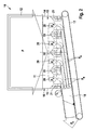
- a first embodiment of an emptying magazine 10 comprises a receiving space 11 for the products flowing from containers 12, for example trays or shaft trays.
- the receiving space 11 is limited to all sides. This means that the Receiving space 11 by side walls 13, 14, a front wall 15 (the sake of clarity omitted in the illustration) and a rear wall 16 is limited.
- the receiving space is open and optionally covered by suitable closing elements.
- Down the receiving space 11 is limited by a conveying element 17.
- the conveying element 17 is arranged at a distance from the receiving space 11 so that the conveying element 17 forms a channel 18 in which the products are transported away.
- at least one current regulating element 19 is arranged within the receiving space 11, at least one current regulating element 19 is arranged. Preferably, however, a plurality of current regulating elements 19 are provided.
- current regulating elements 19 can be arranged.
- the current regulating elements 19 are arranged in the receiving space 11 so that they divide the receiving space 11 preferably in the outlet region of the products from the receiving space 11 in vertically directed channels 20.
- three current regulating elements 19 four parallel channels 20 are formed, wherein in the region of the side walls 13, 14 adapted power regulating elements 21 are provided.
- the current regulating elements 19, 21 are used in particular for controlling the product flow within the emptying magazine 10.
- Below the current regulating elements 19, 21, the conveying element 17 is arranged below the current regulating elements 19, 21, the conveying element 17 is arranged. The distance between the conveying element 17 and the or each current regulating element 19, 21 is adjustable.
- the channel 18 forming conveyor element 17 for transporting the products is arranged inclined with respect to the receiving space 11 and to the current regulating elements 19, 21.
- the conveyor element 17 extends obliquely downward, so that the distance of the conveyor element 17 from the one side wall 14 is less than from the opposite side wall 13.
- the distance between the conveyor element 17 and the current regulating elements 19, 21 adjustable depending on the diameter of the products.
- the current regulating elements 19, 21 with the same shape / shape or the conveyor belt are movable up and down. Also a superimposed movement of Stromregultechnikmaschinesmaschine 19, 21 on the one hand and conveying element 21 on the other hand is possible.
- the conveying element 17 is positioned below the receiving space 11 or the current regulating elements 19, 21 in such a way that the same number of product layers is formed from each of the vertically extending channels 20.
- the inclination angle ⁇ of the conveying element 17 is adjustable as a function of the diameter of the products, but preferably independently of the distance adjustability of the current regulating elements 19, 21 and / or the conveying element 17.
- the Abstandsein auskeit also takes place depending on the diameter of the products.
- the current regulating elements 19, 21 as a whole and / or the conveying element 17 are adjustable in height in a linear direction.
- the conveying element 17 - with the exception of the adjustability of the inclination angle ⁇ - stationary, while the current regulating elements 19, 21 are all synchronized up and down movable.
- the total height of the mass flow In addition to the diameter of the products can be considered as a further criterion, the total height of the mass flow. In the tobacco processing industry in particular the heights 80mm, 100mm and 120mm have prevailed for the mass flow to be removed.
- all current regulating elements 19, 21 are arranged on a common carrier 22, which is vertically adjustable in height.
- the carrier 22 is assigned at least one drive 23.
- two drives 23, 24 are provided, which are preferably designed as spindle drives.
- the carrier 22 also manually, for example via threaded rods, winches or the like, be actuated.
- the current regulating elements 19, 21 are optionally arranged to be adjustable in the horizontal direction, so that the width of the vertically directed channels 20 is adjustable.
- the number of current regulating elements 19, 21 can be varied. In principle, all current regulating elements 19, 21 are identical. In the first place, this applies to the power regulation elements 19 arranged freely in the receiving space 11.
- the power regulation elements 21 lying on the side walls 13, 14 are also identical to one another. Opposite the freely arranged in the receiving space 11 Stromregultechniks instituten 19, the lying on the outer sides of the current regulating elements 21 are formed only split, so that they are adapted on the one hand to the side walls 13, 14 and on the other hand on the channels 20 side facing identical to the current regulating elements 19. In height, which essentially determines the shape and design of the channels 20, all current regulating elements 19, 21 have the same dimensions. Also, the distances between the current regulating elements 19, 21 are the same, so that the channels 20 are equal not only in height but also in width.
- a drive 25 is associated with this, which is preferably designed as a spinel drive.
- the conveyor element 17 may also have additional drives for height adjustment.
- All drives 23, 24, 25 are connected to controls.
- all drives 23 to 25 are connected to a common (not explicitly shown) control.
- the controller may also be operatively connected in conjunction with a measuring element or the like.
- a measuring element for measuring / detecting the diameter of the products may be provided.
- the drives 23 to 25 for adjusting the inclination angle ⁇ and / or the distance between the conveying element 17 and the current regulating elements 19, 21 control.
- the respective diameter of the products may be transmitted via an input field or the like e.g. is specified or input to an operator terminal to control the drives 23 to 25.
- the side walls 13, 14 are - based on the products or the product geometry - preferably format independent and fixed to a frame 26, housing or the like.
- the front wall 15 is formed as a viewing window and format-dependent.
- the lens is adjustable.
- the adjustability of the inclination angle ⁇ and the distance between the conveying element 17 and the current regulating elements 19, 21 depends on the diameter of the products and the number of channels 20.
- the internal width of the containers to be emptied may also be an adjustment parameter.
- the angle of inclination ⁇ and the distance between the conveying element 17 and the flow regulating elements 19, 21 can be depicted as a function of the diameter of the products and / or the inner width of the containers 12.
- a container 12 filled with products is brought or pivoted manually or automatically with suitable aids in the usual way via the head into the region of a connection means of the emptying magazine 10.
- the products fall into the receiving space 11 of the emptying magazine 10 directly or after opening a closing element.
- the product stream formed from the products is supplied through the receiving space 11 and through the channels 20 to the conveying element 17, which delivers the product flow through the channel 18 from the emptying magazine 10 transported.
- the product flow P see, for example, FIG. 2
- the product flow P in the region of the current regulating elements 19, 21 into smaller product streams P K (see, for example, US Pat FIG. 2 ) divided.
- the current regulation elements 19, 21 regulate the inflowing product flow P, so that it is evenly divided into individual equal product flows P K on the channels 20 and with approximately equal paths after the flow regulating elements 19, 21 in the region of the channel 18 again to a common product flow P A (see FIG. 2 ) is brought together and transported away.
- the vertically flowing product streams P K are virtually deflected by the conveying element 17 and each form a corresponding to the inclination of the conveying element 17 inclined product flow P N.
- the individual product streams P N lie above one another and form the common product stream P A.
- the width of the product streams P K and the height of the product streams P N are the same.
- the product streams P N are formed from at least one layer of products, but preferably from several product layers.
- the product layer height of the common product flow P A ie the stacked number of products or product layers, is basically divisible by the number of channels 20.
- the distance between the current regulating elements 19, 21 and the Conveying element 17 is selected such that each product flow P N consists of an integer number of product layers.
- the number of channels 20 depends in particular on the width of the drawer to be emptied. The wider a Schragen, the greater the number of channels 20 and vice versa.
- the product flow P A formed from the individual product streams P K and P N is discharged obliquely downwards. This means that all the individual product streams P K flowing out of the channels 20 travel the same way until they reach the conveying element 17 or the product stream P N of the upstream channel 20 or the product streams P N of the upstream channels 20 thereupon to meet.
- the distance between the conveying element 17 and the current regulating elements 19, 21, more precisely between the top of the conveying element 17 and the lower edges of the current regulating elements 19, 21, is adjusted depending on the diameter of the products.
- the product stream P A is then combined with a further, for example from a production machine ("Maker") originating product flow P M to a total mass flow P G (see, eg FIG. 3 ).
- the inclination or the inclination angle ⁇ and the distance between the conveying element 17 and the current regulating elements 19, 21 can be adjusted independently of each other. Preferably, however, a direct relationship between these two parameters is established by means of the higher-level controller.
- the channels 20 are formed in such a way, in particular by positioning the Stromregul michsetti 19, 21 horizontally to each other that the product streams P K all the same width and when hitting the conveyor element 17 or lying already on the conveyor element 17 product flow P K the same height exhibit.
- the distance adjustment between the conveying element 17 and the current regulating elements 19, 21 is preferably achieved in that all current regulating elements 19, 21 adjusted by a common carrier 22 in height, so be moved up and down.
- the adjustment of the height of the current regulating elements 19, 21 and the inclination of the conveying element 17 is effected by suitable drives 23, 24, 25.
- the diameters of the products are measured.
- the measurement result is transmitted via a control to the drives 23, 24, 25 further given, so that the inclination angle ⁇ and / or the distance between the conveying element 17 and the current regulating elements 19, 21 is set accordingly.
- the diameter size can also be entered via suitable input fields, buttons or the like and used for control.
- a product change should take place for example products with a different diameter
- this can be entered via the controller, for example via a touch screen or the like by the operator.
- the diameter can be transferred by data link to and from the cigarette or filter rod making machine to use this value for automatic adjustment. Subsequently, the inclination and / or the distance are adjusted automatically, so that an optimized and even outflow of the product flow is ensured.
- the mass flow P A flows from the discharge hopper 10 via the conveying element 17 in an orifice region 27 of the channel 18.
- the mass flow P A is passed through the mouth region 27 and hits at an acute angle (acute angle means less than 90 °) the lower mass flow P M , which is transported on a conveying element 28.
- the mass flows P A and P M meet and unite to the common mass flow P G , which is preferably transported away on an additional conveyor element 29.
- the two conveying elements 28 and 29 may be connected to one another with a guide plate 50 or the like.
- the guide plate 50 or a corresponding element can bridge the distance between the two conveying elements 28, 29.
- the region of the transition between the two conveying elements 28, 29 is arranged substantially below the mouth region 27.
- the baffle 50 is arranged in an impact area of the products flowing out of the mouth region 27.
- the mouth region 27 can, as in FIG. 3 shown, a simple extension of the channel 18, wherein the extension of a lower guide element 30 and an upper guide element 31 is formed.
- the two guide elements 30, 31 are curved.
- the upper guide element 31 is pivotally formed about a pivot point S. In the case of a flatter mass flow P A or to stop the mass flow P A , the upper guide element 31 falls down. More specifically, the guide member 31 pivots counterclockwise about the pivot point S to narrow the mouth portion 27. As soon as the mass flow P A is again transported at full height, the mass flow P A pushes the guide element 31 back into the open position (as in FIG FIG. 3 shown).
- a device 32 In the mouth region 27, however, a device 32 according to the FIGS. 4 to 6 be arranged.
- the device 32 may be an integral part of the emptying magazine 10, but alternatively be used as an independent device 32 for merging any mass flows.
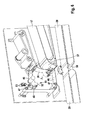
- the device 32 comprises a first guide element 33 and a second guide element 34 arranged above the first guide element 33. Both guide elements 33, 34 form an outlet channel 35 for merging the mass flow P A flowing from the outlet channel 35 with another, at an acute angle the mass flow P A striking mass flow P M.
- the upper guide element 34 is designed as a delimiting element 36 for regulating the mass flow P A flowing out of the outlet channel 35 and for forming a compensation reservoir.
- the limiting element 36 is designed to be movable.
- the restriction member 36 is pivotally mounted, for example, on a side wall, a frame or frame or the like. Due to the pivoting of the limiting element 36, the distance between the lower guide element 33, which may be, for example, a simple bent plate 37, a driven conveyor or the like, to increase or decrease the mouth channel 35 is variable. Due to the pivoting of the limiting element 36, this is also suitable as a compensation reservoir. With the deflection, ie in particular the enlargement of the mouth channel 35, the receiving or storage volume in the region of the mouth channel 35 increases.
- Other embodiments of the limiting element 36 to create a compensation reservoir such as a flexible band member or the like, but also possible.
- the limiting element 36 is pivotably arranged, specifically in a pivot point S.
- the limiting element 36 is associated with a pendulum arm 38.
- the limiting element 36 and the pendulum arm 38 form a preferably detachable unit, which is pivotable about the pivot point S.
- the pendulum arm 38 itself can serve as an actuating mechanism for the pivoting movement.
- the pendulum arm 38 is associated with an additional actuating mechanism.
- the pendulum arm 38 is assigned a weight 40 at a free end 39.
- Other actuating mechanisms such as servo motors or the like are also used.
- the weight 40 is replaceable and in particular also at different positions of the pendulum arm 38, which forms a lever arm about the pivot point S, to fix the center of gravity of the weight 40 to move.
- the pendulum arm 38 may be associated with a position sensor 51, which consists for example of a trigger element 52 and at least one, but preferably more and more preferably three proximity sensors 53, sensors or the like.
- the position of the triggering element 52 can serve to control, for example, the conveying speeds of the conveying element 17 and / or of the conveying element 28 and / or of the conveying element 29.
- In the FIG. 4 are all proximity switches 53 covered by the trigger element 52, which may mean, for example, that the mouth channel 35 is open to the maximum.
- In the FIG. 5 are all proximity switches 53 free, which may mean that the mouth channel 35 is closed. Other positions of the trigger element 52 thus define a modified opening of the mouth channel 35.
- a blocking element 42 is arranged at the free end 41 of the limiting element 36, ie at the pivot point S opposite end.
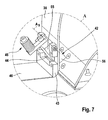
- the locking element 42 is pivotally mounted on the limiting element 36 and is preferably designed as a simple folding element or the like. More specifically, the locking member 42 is pivotally mounted on a frame 43 which is disposed at the free end 41.
- the blocking element 42 which may be a simple plate, a block-like element or the like, is pivotable through a recess 44 in the limiting element 36 from the mouth channel 35 releasing position into a mouth channel 35 closing position and vice versa (see in particular FIGS. 6 and 7 ).
- the blocking element 42 has two sections 55, 56. One of the sections 55, 56, For example, the portion 56, projects, at least in a closed position, in the mouth channel 35, while the other portion 55 is always, so regardless of the pivot position, outside the mouth channel 35.
- an actuating element 45 is arranged at the second, always located outside of the mouth channel 35 section 55.
- the actuating element 45 is preferably adjustable.
- the actuating element 45 is a variable weight, which is formed, for example, from washers fixed with a screw.
- the actuating element 45 may also be a knurled screw whose distance from the blocking element 42 is variable. Also, the distance to the pivot axis A S can optionally be varied or adjusted.
- other actuators 45 such as simple nuts, weights, spring elements, actuators or the like can be used.
- a band member 46 or the like is articulated.
- the band member 46 is guided over at least two, but preferably three deflection rollers 47 and provided at the fastening element 36 opposite end with a weight 48.
- the weight 48 is depending on the position of the locking element 42 up or down, due to the connection with the band member 46 is pulled. In the open position of the blocking element 42, the weight 48 is in a lower position (see FIG. 4 ), while the weight 48 is in the closed position of the locking element 42 in the upper position (see FIG. 5 ).
- the mode of operation of the device 32 will be described below on the basis of the merging of the mass flow P A flowing from the emptying magazine 10 with the mass flow P M flowing from a production machine.
- the mass flow P A flows through the channel 18 and presses the limiting element 36 so that the mouth channel 35 is open.
- the pendulum arm 38 is pivoted with the limiting element 36 in an open position.
- the mass flow P A flows through the orifice passage 35, which directs the mass flow 35 obliquely downward at an acute angle to the mass flow P M.
- the two mass flows P A and P M unite to the mass flow P G.
- the limiting element 36 pivots preferably by gravity against the mass flow P A. This leads to a narrowing of the mouth channel 35, so that forms a kind of product graft in the bottleneck, which blocks the mouth channel 35. This creates a free space in the mouth region 27, that is, a space free of products.
- the blocking element 42 tilts with the section 56 into the mouth channel 35. In other words, the blocking element 42 works with the section 55 away from the limiting element 36 , so that the mouth channel 35 is completely closed (see FIGS.
- the possibly remaining distance between the blocking element 42 and the guide element 33 is preferably smaller than the diameter of the products to be conveyed. This also the occasional lagging or falling out of products from the mass flow P A is effectively prevented.
- the mass flow P A can thus be exactly guided and regulated by the device 32.
- the limiting element 36 and / or the blocking element 42 can be actively controlled, namely moved or pivoted.
- the control of the device 32 can be done via its own control, but also via a control of upstream or downstream devices or machines.
Landscapes
- Filling Or Emptying Of Bunkers, Hoppers, And Tanks (AREA)
- Cigarettes, Filters, And Manufacturing Of Filters (AREA)
- Manufacturing Of Cigar And Cigarette Tobacco (AREA)
- Branching, Merging, And Special Transfer Between Conveyors (AREA)
Priority Applications (2)
| Application Number | Priority Date | Filing Date | Title |
|---|---|---|---|
| PL10075068T PL2220950T3 (pl) | 2009-02-18 | 2010-02-17 | Magazyn opróżniania i sposób opróżniania napełnionych sztabkowymi produktami kaset, zwłaszcza kaset pionowych |
| EP11151513.6A EP2359704B1 (fr) | 2009-02-18 | 2010-02-17 | Dispositif et procédé de réunion de flux de matière, notamment pour une cartouche de vidage |
Applications Claiming Priority (1)
| Application Number | Priority Date | Filing Date | Title |
|---|---|---|---|
| DE102009009831A DE102009009831A1 (de) | 2009-02-18 | 2009-02-18 | Entleermagazin und Verfahren zum Entleeren von mit stabförmigen Produkten gefüllten Schragen, insbesondere Schachtschragen sowie Einrichtung zum Zusammenführen von Massenströmen insbesondere für ein Entleermagazin |
Related Child Applications (3)
| Application Number | Title | Priority Date | Filing Date |
|---|---|---|---|
| EP11151513.6A Division-Into EP2359704B1 (fr) | 2009-02-18 | 2010-02-17 | Dispositif et procédé de réunion de flux de matière, notamment pour une cartouche de vidage |
| EP11151513.6A Division EP2359704B1 (fr) | 2009-02-18 | 2010-02-17 | Dispositif et procédé de réunion de flux de matière, notamment pour une cartouche de vidage |
| EP11151513.6 Division-Into | 2011-01-20 |
Publications (4)
| Publication Number | Publication Date |
|---|---|
| EP2220950A2 true EP2220950A2 (fr) | 2010-08-25 |
| EP2220950A3 EP2220950A3 (fr) | 2010-11-03 |
| EP2220950A9 EP2220950A9 (fr) | 2011-03-09 |
| EP2220950B1 EP2220950B1 (fr) | 2016-12-14 |
Family
ID=42145183
Family Applications (2)
| Application Number | Title | Priority Date | Filing Date |
|---|---|---|---|
| EP11151513.6A Not-in-force EP2359704B1 (fr) | 2009-02-18 | 2010-02-17 | Dispositif et procédé de réunion de flux de matière, notamment pour une cartouche de vidage |
| EP10075068.6A Active EP2220950B1 (fr) | 2009-02-18 | 2010-02-17 | Cartouche de vidage et procédé de vidage de combles remplis de produits en forme de tiges, notamment combles de puits |
Family Applications Before (1)
| Application Number | Title | Priority Date | Filing Date |
|---|---|---|---|
| EP11151513.6A Not-in-force EP2359704B1 (fr) | 2009-02-18 | 2010-02-17 | Dispositif et procédé de réunion de flux de matière, notamment pour une cartouche de vidage |
Country Status (4)
| Country | Link |
|---|---|
| EP (2) | EP2359704B1 (fr) |
| CN (1) | CN102058158B (fr) |
| DE (1) | DE102009009831A1 (fr) |
| PL (2) | PL2220950T3 (fr) |
Cited By (2)
| Publication number | Priority date | Publication date | Assignee | Title |
|---|---|---|---|---|
| EP3028585A1 (fr) * | 2014-12-02 | 2016-06-08 | HAUNI Maschinenbau AG | Dispositif formé et équipé pour l'introduction automatique et en portions d'articles en forme de tige de l'industrie de traitement du tabac à partir d'un magasin sur une unité en aval ainsi que dispositif de transfert équipé d'un tel dispositif |
| EP3305100A1 (fr) * | 2016-10-07 | 2018-04-11 | Hauni Maschinenbau GmbH | Dispositif et procédé pour reunir deux flux d'articles en forme de tige dans l'industrie du tabac |
Families Citing this family (6)
| Publication number | Priority date | Publication date | Assignee | Title |
|---|---|---|---|---|
| DE102013102807B3 (de) * | 2013-03-19 | 2014-08-07 | Hauni Maschinenbau Ag | Speichereinrichtung mit variabler Speicherkapazität und Verfahren zum Transportieren und Speichern eines aus stabförmigen Artikeln der Tabak verarbeitenden Industrie gebildeten, mehrlagigen Massenstroms |
| CH708586A1 (de) * | 2013-09-16 | 2015-03-31 | M Tanner Ag | System zum Justieren von zumindest der Höheneinstellung zwischen einer ersten Transporteinrichtung und einer zweiten Transporteinrichtung. |
| CN104016078B (zh) * | 2014-06-13 | 2016-05-25 | 北京天申正祥科技有限公司 | 一种用于输送棒状物料的柔性转弯装置 |
| DE102015009740B4 (de) * | 2015-07-31 | 2018-10-11 | Hauni Maschinenbau Gmbh | Entleermagazin und Verfahren zum Entleeren von mit stabförmigen Artikeln der Tabak verarbeitenden Industrie gefüllten Schragen |
| CN106628818A (zh) * | 2016-12-22 | 2017-05-10 | 重庆淳祥电子科技有限公司 | 带自动收片装置的除尘机 |
| CN110668131A (zh) * | 2019-10-10 | 2020-01-10 | 龙岩烟草工业有限责任公司 | 烟支输送装置以及卷烟存储输送系统 |
Citations (6)
| Publication number | Priority date | Publication date | Assignee | Title |
|---|---|---|---|---|
| GB2165529A (en) | 1984-10-11 | 1986-04-16 | Gd Spa | Device for supplying rod-shaped articles |
| DE4014713A1 (de) | 1990-05-08 | 1991-11-14 | Hauni Werke Koerber & Co Kg | Vorrichtung zum zusammenfuehren von zwei massenstroemen aus stabfoermigen artikeln der tabakverarbeitenden industrie |
| DE4127283A1 (de) | 1991-08-03 | 1993-02-04 | Focke & Co | Vorrichtung zum foerdern von zigaretten im zusammenhang mit einer verpackungsmaschine |
| US20050098744A1 (en) | 2002-09-11 | 2005-05-12 | Hauni Maschinenbau Ag | Process and device for measuring the length and/or the diameter of filter bars |
| DE102007005749A1 (de) | 2007-01-31 | 2008-08-14 | Hauni Maschinenbau Ag | Entleermagazin und Verfahren zum Entleeren von mit stabförmigen Produkten gefüllten Schragen, insbesondere Schachtschragen |
| DE102007012697A1 (de) | 2007-03-13 | 2008-09-18 | Hauni Maschinenbau Ag | Entleermagazin für eine Schragenentleereinrichtung zum Entleeren von mit stabförmigen Produkten gefüllten Schragen |
Family Cites Families (10)
| Publication number | Priority date | Publication date | Assignee | Title |
|---|---|---|---|---|
| NL7102038A (fr) * | 1971-02-16 | 1972-08-18 | ||
| IT1184270B (it) * | 1984-04-09 | 1987-10-22 | Molins Plc | Sistema di trasporto per oggetti simili a bastoncini come sigarette e simili |
| US5217101A (en) * | 1990-05-08 | 1993-06-08 | Korber Ag | Apparatus for merging mass flows of rod-shaped articles of the tobacco processing industry |
| DE19938542A1 (de) * | 1999-08-18 | 2001-02-22 | Hauni Maschinenbau Ag | Umlenkung für einen Massenstrom |
| DE102004055629A1 (de) * | 2004-11-12 | 2006-05-24 | Hauni Maschinenbau Ag | Vorrichtung und Verfahren zum aufeinanderfolgenden Entleeren von mit Artikeln gefüllten Behältern |
| ITBO20050308A1 (it) * | 2005-05-03 | 2005-08-02 | Gd Spa | Dispositivo per la gestione di masse di articoli cilindrici |
| ITBO20050450A1 (it) * | 2005-07-04 | 2007-01-05 | Gd Spa | Metodo ed apparecchiatura per la movimentazione ed il trasferimento a lotti di articoli da fumo |
| DE102005034246A1 (de) * | 2005-07-19 | 2007-02-01 | Hauni Maschinenbau Ag | Speichervorrichtung für stabförmige Artikel sowie Vorrichtung und Verfahren zum Befüllen von Speichervorrichtungen |
| PL211204B1 (pl) * | 2006-08-18 | 2012-04-30 | Int Tobacco Machinery Poland | Sposób rozładowywania kaset stosowanych w przemyśle tytoniowym |
| DE102007006133A1 (de) * | 2007-02-03 | 2008-08-07 | Hauni Maschinenbau Ag | Entleermagazin und Verfahren zum Entleeren von mit stabförmigen Produkten gefüllten Schachtschragen |
-
2009
- 2009-02-18 DE DE102009009831A patent/DE102009009831A1/de not_active Withdrawn
-
2010
- 2010-02-17 EP EP11151513.6A patent/EP2359704B1/fr not_active Not-in-force
- 2010-02-17 PL PL10075068T patent/PL2220950T3/pl unknown
- 2010-02-17 PL PL11151513T patent/PL2359704T3/pl unknown
- 2010-02-17 EP EP10075068.6A patent/EP2220950B1/fr active Active
- 2010-02-22 CN CN201010120483.0A patent/CN102058158B/zh active Active
Patent Citations (6)
| Publication number | Priority date | Publication date | Assignee | Title |
|---|---|---|---|---|
| GB2165529A (en) | 1984-10-11 | 1986-04-16 | Gd Spa | Device for supplying rod-shaped articles |
| DE4014713A1 (de) | 1990-05-08 | 1991-11-14 | Hauni Werke Koerber & Co Kg | Vorrichtung zum zusammenfuehren von zwei massenstroemen aus stabfoermigen artikeln der tabakverarbeitenden industrie |
| DE4127283A1 (de) | 1991-08-03 | 1993-02-04 | Focke & Co | Vorrichtung zum foerdern von zigaretten im zusammenhang mit einer verpackungsmaschine |
| US20050098744A1 (en) | 2002-09-11 | 2005-05-12 | Hauni Maschinenbau Ag | Process and device for measuring the length and/or the diameter of filter bars |
| DE102007005749A1 (de) | 2007-01-31 | 2008-08-14 | Hauni Maschinenbau Ag | Entleermagazin und Verfahren zum Entleeren von mit stabförmigen Produkten gefüllten Schragen, insbesondere Schachtschragen |
| DE102007012697A1 (de) | 2007-03-13 | 2008-09-18 | Hauni Maschinenbau Ag | Entleermagazin für eine Schragenentleereinrichtung zum Entleeren von mit stabförmigen Produkten gefüllten Schragen |
Cited By (2)
| Publication number | Priority date | Publication date | Assignee | Title |
|---|---|---|---|---|
| EP3028585A1 (fr) * | 2014-12-02 | 2016-06-08 | HAUNI Maschinenbau AG | Dispositif formé et équipé pour l'introduction automatique et en portions d'articles en forme de tige de l'industrie de traitement du tabac à partir d'un magasin sur une unité en aval ainsi que dispositif de transfert équipé d'un tel dispositif |
| EP3305100A1 (fr) * | 2016-10-07 | 2018-04-11 | Hauni Maschinenbau GmbH | Dispositif et procédé pour reunir deux flux d'articles en forme de tige dans l'industrie du tabac |
Also Published As
| Publication number | Publication date |
|---|---|
| PL2359704T3 (pl) | 2017-07-31 |
| EP2220950A3 (fr) | 2010-11-03 |
| EP2220950A9 (fr) | 2011-03-09 |
| EP2359704A1 (fr) | 2011-08-24 |
| CN102058158A (zh) | 2011-05-18 |
| DE102009009831A1 (de) | 2010-08-26 |
| EP2220950B1 (fr) | 2016-12-14 |
| EP2359704B1 (fr) | 2017-01-04 |
| PL2220950T3 (pl) | 2017-05-31 |
| CN102058158B (zh) | 2015-07-01 |
Similar Documents
| Publication | Publication Date | Title |
|---|---|---|
| EP2220950B1 (fr) | Cartouche de vidage et procédé de vidage de combles remplis de produits en forme de tiges, notamment combles de puits | |
| DE69626731T2 (de) | Körnchenbarriere und Körnchenwägeapparat damit | |
| EP1952706A1 (fr) | Magasin de vidage et procédé de vidage de récipients remplis de produits en forme de tige, en particulier récipients en forme de colonne | |
| EP2369949B1 (fr) | Équipement et procédé d'amenée de tabac haché entre une unité de chargement du tabac et une machine de transformation du tabac | |
| DE1586073C3 (de) | Vorrichtung zum Beschicken des Speiseschachts einer Zigarettenmaschine | |
| DE112019004566B4 (de) | System zum Zuführen eines granulierten Materials und dabei verwendetes Zuführverfahren | |
| DE69819402T2 (de) | Sich automatisch anpassender Former in einer Verpackungsvorrichtung und Betriebsverfahren | |
| EP2120615B1 (fr) | Magasin de vidage pour un dispositif de vidage de conteneur conçu pour vider des conteneurs remplis de produits en forme de tige | |
| DE102007006133A1 (de) | Entleermagazin und Verfahren zum Entleeren von mit stabförmigen Produkten gefüllten Schachtschragen | |
| DE60221509T2 (de) | Vorrichtung zum zuführen von zigaretten zu einer verpackungsmaschine | |
| EP1177731A2 (fr) | Dispositif et procédé pour l'autofabrication de cigarettes | |
| EP0979393B1 (fr) | Dépense d'un produit avec des récipients mouvants | |
| EP0677723A1 (fr) | Balance de remplissage | |
| EP2260732A1 (fr) | Dispositif et procédé de vidage successif de récipients remplis de produits en forme de tiges | |
| EP2150138B1 (fr) | Magasin de vidage et dispositif de transfert pour dispositif de vidage de caissons, ainsi que dispositif de vidage de caissons | |
| DE1449926B1 (de) | Abwägevorrichtung | |
| DE3230144C2 (fr) | ||
| EP3679810B1 (fr) | Dispositif de stockage pour articles en forme de boudin de l'industrie de traitement du tabac | |
| EP0273254B1 (fr) | Procédé et dispositif pour remplir des matières en vrac, spécialement du café | |
| EP3135128A2 (fr) | Station de vidage de baquets destinée à vider des baquets remplis de produits en forme de tige et procédé pour vider des baquets remplis de produits en forme de tige à l'aide d'une station de vidage de baquets | |
| DE102007040173A1 (de) | Vorrichtung und Verfahren zum Zusammenführen von aus stabförmigen Artikeln gebildeten Massenströmen | |
| EP3430917A1 (fr) | Dispositif d'introduction automatique et par portions d'articles en forme de tige de l'industrie de traitement du tabac à partir d'une cartouche sur une unité en aval ainsi que dispositif de transfert doté d'un tel dispositif | |
| EP1184648B1 (fr) | Distributeur pour un système de distribution de produit | |
| DE1586076C3 (de) | Vorrichtung zur direkten Einspeisung eines Zigarettenflusses in den Speisetrichter einer Zigarettenverpackungsmaschine | |
| EP0673211A1 (fr) | Dispositif de stockage. |
Legal Events
| Date | Code | Title | Description |
|---|---|---|---|
| PUAI | Public reference made under article 153(3) epc to a published international application that has entered the european phase |
Free format text: ORIGINAL CODE: 0009012 |
|
| AK | Designated contracting states |
Kind code of ref document: A2 Designated state(s): AT BE BG CH CY CZ DE DK EE ES FI FR GB GR HR HU IE IS IT LI LT LU LV MC MK MT NL NO PL PT RO SE SI SK SM TR |
|
| AX | Request for extension of the european patent |
Extension state: AL BA RS |
|
| PUAL | Search report despatched |
Free format text: ORIGINAL CODE: 0009013 |
|
| AK | Designated contracting states |
Kind code of ref document: A3 Designated state(s): AT BE BG CH CY CZ DE DK EE ES FI FR GB GR HR HU IE IS IT LI LT LU LV MC MK MT NL NO PL PT RO SE SI SK SM TR |
|
| AX | Request for extension of the european patent |
Extension state: AL BA RS |
|
| 17P | Request for examination filed |
Effective date: 20110502 |
|
| TPAC | Observations filed by third parties |
Free format text: ORIGINAL CODE: EPIDOSNTIPA |
|
| 17Q | First examination report despatched |
Effective date: 20151021 |
|
| REG | Reference to a national code |
Ref country code: DE Ref legal event code: R079 Ref document number: 502010012864 Country of ref document: DE Free format text: PREVIOUS MAIN CLASS: A24C0005356000 Ipc: A24C0005350000 |
|
| RIC1 | Information provided on ipc code assigned before grant |
Ipc: A24C 5/35 20060101AFI20160523BHEP |
|
| GRAP | Despatch of communication of intention to grant a patent |
Free format text: ORIGINAL CODE: EPIDOSNIGR1 |
|
| RAP1 | Party data changed (applicant data changed or rights of an application transferred) |
Owner name: HAUNI MASCHINENBAU GMBH |
|
| INTG | Intention to grant announced |
Effective date: 20160707 |
|
| GRAS | Grant fee paid |
Free format text: ORIGINAL CODE: EPIDOSNIGR3 |
|
| GRAA | (expected) grant |
Free format text: ORIGINAL CODE: 0009210 |
|
| AK | Designated contracting states |
Kind code of ref document: B1 Designated state(s): AT BE BG CH CY CZ DE DK EE ES FI FR GB GR HR HU IE IS IT LI LT LU LV MC MK MT NL NO PL PT RO SE SI SK SM TR |
|
| REG | Reference to a national code |
Ref country code: GB Ref legal event code: FG4D Free format text: NOT ENGLISH |
|
| REG | Reference to a national code |
Ref country code: CH Ref legal event code: EP |
|
| REG | Reference to a national code |
Ref country code: IE Ref legal event code: FG4D Free format text: LANGUAGE OF EP DOCUMENT: GERMAN |
|
| REG | Reference to a national code |
Ref country code: AT Ref legal event code: REF Ref document number: 852749 Country of ref document: AT Kind code of ref document: T Effective date: 20170115 |
|
| REG | Reference to a national code |
Ref country code: DE Ref legal event code: R096 Ref document number: 502010012864 Country of ref document: DE |
|
| PG25 | Lapsed in a contracting state [announced via postgrant information from national office to epo] |
Ref country code: LV Free format text: LAPSE BECAUSE OF FAILURE TO SUBMIT A TRANSLATION OF THE DESCRIPTION OR TO PAY THE FEE WITHIN THE PRESCRIBED TIME-LIMIT Effective date: 20161214 |
|
| REG | Reference to a national code |
Ref country code: NL Ref legal event code: FP |
|
| REG | Reference to a national code |
Ref country code: LT Ref legal event code: MG4D |
|
| PG25 | Lapsed in a contracting state [announced via postgrant information from national office to epo] |
Ref country code: LT Free format text: LAPSE BECAUSE OF FAILURE TO SUBMIT A TRANSLATION OF THE DESCRIPTION OR TO PAY THE FEE WITHIN THE PRESCRIBED TIME-LIMIT Effective date: 20161214 Ref country code: NO Free format text: LAPSE BECAUSE OF FAILURE TO SUBMIT A TRANSLATION OF THE DESCRIPTION OR TO PAY THE FEE WITHIN THE PRESCRIBED TIME-LIMIT Effective date: 20170314 Ref country code: GR Free format text: LAPSE BECAUSE OF FAILURE TO SUBMIT A TRANSLATION OF THE DESCRIPTION OR TO PAY THE FEE WITHIN THE PRESCRIBED TIME-LIMIT Effective date: 20170315 Ref country code: SE Free format text: LAPSE BECAUSE OF FAILURE TO SUBMIT A TRANSLATION OF THE DESCRIPTION OR TO PAY THE FEE WITHIN THE PRESCRIBED TIME-LIMIT Effective date: 20161214 |
|
| PG25 | Lapsed in a contracting state [announced via postgrant information from national office to epo] |
Ref country code: HR Free format text: LAPSE BECAUSE OF FAILURE TO SUBMIT A TRANSLATION OF THE DESCRIPTION OR TO PAY THE FEE WITHIN THE PRESCRIBED TIME-LIMIT Effective date: 20161214 Ref country code: BE Free format text: LAPSE BECAUSE OF NON-PAYMENT OF DUE FEES Effective date: 20170228 Ref country code: FI Free format text: LAPSE BECAUSE OF FAILURE TO SUBMIT A TRANSLATION OF THE DESCRIPTION OR TO PAY THE FEE WITHIN THE PRESCRIBED TIME-LIMIT Effective date: 20161214 |
|
| PG25 | Lapsed in a contracting state [announced via postgrant information from national office to epo] |
Ref country code: RO Free format text: LAPSE BECAUSE OF FAILURE TO SUBMIT A TRANSLATION OF THE DESCRIPTION OR TO PAY THE FEE WITHIN THE PRESCRIBED TIME-LIMIT Effective date: 20161214 Ref country code: EE Free format text: LAPSE BECAUSE OF FAILURE TO SUBMIT A TRANSLATION OF THE DESCRIPTION OR TO PAY THE FEE WITHIN THE PRESCRIBED TIME-LIMIT Effective date: 20161214 Ref country code: IS Free format text: LAPSE BECAUSE OF FAILURE TO SUBMIT A TRANSLATION OF THE DESCRIPTION OR TO PAY THE FEE WITHIN THE PRESCRIBED TIME-LIMIT Effective date: 20170414 Ref country code: SK Free format text: LAPSE BECAUSE OF FAILURE TO SUBMIT A TRANSLATION OF THE DESCRIPTION OR TO PAY THE FEE WITHIN THE PRESCRIBED TIME-LIMIT Effective date: 20161214 Ref country code: CZ Free format text: LAPSE BECAUSE OF FAILURE TO SUBMIT A TRANSLATION OF THE DESCRIPTION OR TO PAY THE FEE WITHIN THE PRESCRIBED TIME-LIMIT Effective date: 20161214 |
|
| PG25 | Lapsed in a contracting state [announced via postgrant information from national office to epo] |
Ref country code: PT Free format text: LAPSE BECAUSE OF FAILURE TO SUBMIT A TRANSLATION OF THE DESCRIPTION OR TO PAY THE FEE WITHIN THE PRESCRIBED TIME-LIMIT Effective date: 20170414 Ref country code: ES Free format text: LAPSE BECAUSE OF FAILURE TO SUBMIT A TRANSLATION OF THE DESCRIPTION OR TO PAY THE FEE WITHIN THE PRESCRIBED TIME-LIMIT Effective date: 20161214 Ref country code: BG Free format text: LAPSE BECAUSE OF FAILURE TO SUBMIT A TRANSLATION OF THE DESCRIPTION OR TO PAY THE FEE WITHIN THE PRESCRIBED TIME-LIMIT Effective date: 20170314 Ref country code: SM Free format text: LAPSE BECAUSE OF FAILURE TO SUBMIT A TRANSLATION OF THE DESCRIPTION OR TO PAY THE FEE WITHIN THE PRESCRIBED TIME-LIMIT Effective date: 20161214 |
|
| REG | Reference to a national code |
Ref country code: DE Ref legal event code: R097 Ref document number: 502010012864 Country of ref document: DE |
|
| PG25 | Lapsed in a contracting state [announced via postgrant information from national office to epo] |
Ref country code: MC Free format text: LAPSE BECAUSE OF FAILURE TO SUBMIT A TRANSLATION OF THE DESCRIPTION OR TO PAY THE FEE WITHIN THE PRESCRIBED TIME-LIMIT Effective date: 20161214 |
|
| REG | Reference to a national code |
Ref country code: CH Ref legal event code: PL |
|
| PLBE | No opposition filed within time limit |
Free format text: ORIGINAL CODE: 0009261 |
|
| STAA | Information on the status of an ep patent application or granted ep patent |
Free format text: STATUS: NO OPPOSITION FILED WITHIN TIME LIMIT |
|
| PG25 | Lapsed in a contracting state [announced via postgrant information from national office to epo] |
Ref country code: CH Free format text: LAPSE BECAUSE OF NON-PAYMENT OF DUE FEES Effective date: 20170228 Ref country code: LI Free format text: LAPSE BECAUSE OF NON-PAYMENT OF DUE FEES Effective date: 20170228 |
|
| 26N | No opposition filed |
Effective date: 20170915 |
|
| GBPC | Gb: european patent ceased through non-payment of renewal fee |
Effective date: 20170314 |
|
| REG | Reference to a national code |
Ref country code: IE Ref legal event code: MM4A |
|
| PG25 | Lapsed in a contracting state [announced via postgrant information from national office to epo] |
Ref country code: DK Free format text: LAPSE BECAUSE OF FAILURE TO SUBMIT A TRANSLATION OF THE DESCRIPTION OR TO PAY THE FEE WITHIN THE PRESCRIBED TIME-LIMIT Effective date: 20161214 |
|
| REG | Reference to a national code |
Ref country code: FR Ref legal event code: ST Effective date: 20171031 |
|
| PG25 | Lapsed in a contracting state [announced via postgrant information from national office to epo] |
Ref country code: LU Free format text: LAPSE BECAUSE OF NON-PAYMENT OF DUE FEES Effective date: 20170217 |
|
| PG25 | Lapsed in a contracting state [announced via postgrant information from national office to epo] |
Ref country code: FR Free format text: LAPSE BECAUSE OF NON-PAYMENT OF DUE FEES Effective date: 20170228 |
|
| REG | Reference to a national code |
Ref country code: BE Ref legal event code: MM Effective date: 20170228 |
|
| PG25 | Lapsed in a contracting state [announced via postgrant information from national office to epo] |
Ref country code: GB Free format text: LAPSE BECAUSE OF NON-PAYMENT OF DUE FEES Effective date: 20170314 Ref country code: IE Free format text: LAPSE BECAUSE OF NON-PAYMENT OF DUE FEES Effective date: 20170217 Ref country code: SI Free format text: LAPSE BECAUSE OF FAILURE TO SUBMIT A TRANSLATION OF THE DESCRIPTION OR TO PAY THE FEE WITHIN THE PRESCRIBED TIME-LIMIT Effective date: 20161214 |
|
| REG | Reference to a national code |
Ref country code: AT Ref legal event code: MM01 Ref document number: 852749 Country of ref document: AT Kind code of ref document: T Effective date: 20170217 |
|
| PG25 | Lapsed in a contracting state [announced via postgrant information from national office to epo] |
Ref country code: AT Free format text: LAPSE BECAUSE OF NON-PAYMENT OF DUE FEES Effective date: 20170217 |
|
| PG25 | Lapsed in a contracting state [announced via postgrant information from national office to epo] |
Ref country code: MT Free format text: LAPSE BECAUSE OF FAILURE TO SUBMIT A TRANSLATION OF THE DESCRIPTION OR TO PAY THE FEE WITHIN THE PRESCRIBED TIME-LIMIT Effective date: 20161214 |
|
| PG25 | Lapsed in a contracting state [announced via postgrant information from national office to epo] |
Ref country code: HU Free format text: LAPSE BECAUSE OF FAILURE TO SUBMIT A TRANSLATION OF THE DESCRIPTION OR TO PAY THE FEE WITHIN THE PRESCRIBED TIME-LIMIT; INVALID AB INITIO Effective date: 20100217 |
|
| PG25 | Lapsed in a contracting state [announced via postgrant information from national office to epo] |
Ref country code: CY Free format text: LAPSE BECAUSE OF NON-PAYMENT OF DUE FEES Effective date: 20161214 |
|
| PG25 | Lapsed in a contracting state [announced via postgrant information from national office to epo] |
Ref country code: MK Free format text: LAPSE BECAUSE OF FAILURE TO SUBMIT A TRANSLATION OF THE DESCRIPTION OR TO PAY THE FEE WITHIN THE PRESCRIBED TIME-LIMIT Effective date: 20161214 |
|
| PG25 | Lapsed in a contracting state [announced via postgrant information from national office to epo] |
Ref country code: TR Free format text: LAPSE BECAUSE OF FAILURE TO SUBMIT A TRANSLATION OF THE DESCRIPTION OR TO PAY THE FEE WITHIN THE PRESCRIBED TIME-LIMIT Effective date: 20161214 |
|
| REG | Reference to a national code |
Ref country code: DE Ref legal event code: R081 Ref document number: 502010012864 Country of ref document: DE Owner name: KOERBER TECHNOLOGIES GMBH, DE Free format text: FORMER OWNER: HAUNI MASCHINENBAU GMBH, 21033 HAMBURG, DE |
|
| REG | Reference to a national code |
Ref country code: NL Ref legal event code: HC Owner name: KOERBER TECHNOLOGIES GMBH; DE Free format text: DETAILS ASSIGNMENT: CHANGE OF OWNER(S), CHANGE OF OWNER(S) NAME; FORMER OWNER NAME: HAUNI MASCHINENBAU GMBH Effective date: 20221020 |
|
| P01 | Opt-out of the competence of the unified patent court (upc) registered |
Effective date: 20230621 |
|
| PGFP | Annual fee paid to national office [announced via postgrant information from national office to epo] |
Ref country code: NL Payment date: 20260228 Year of fee payment: 17 |
|
| PGFP | Annual fee paid to national office [announced via postgrant information from national office to epo] |
Ref country code: DE Payment date: 20260303 Year of fee payment: 17 |
|
| PGFP | Annual fee paid to national office [announced via postgrant information from national office to epo] |
Ref country code: IT Payment date: 20260227 Year of fee payment: 17 |
|
| PGFP | Annual fee paid to national office [announced via postgrant information from national office to epo] |
Ref country code: PL Payment date: 20260121 Year of fee payment: 17 |