EP1837123A1 - Outil destiné au traitement de surfaces et son procédé de fabrication - Google Patents
Outil destiné au traitement de surfaces et son procédé de fabrication Download PDFInfo
- Publication number
- EP1837123A1 EP1837123A1 EP06127136A EP06127136A EP1837123A1 EP 1837123 A1 EP1837123 A1 EP 1837123A1 EP 06127136 A EP06127136 A EP 06127136A EP 06127136 A EP06127136 A EP 06127136A EP 1837123 A1 EP1837123 A1 EP 1837123A1
- Authority
- EP
- European Patent Office
- Prior art keywords
- machining
- tool
- processing
- base body
- disk
- Prior art date
- Legal status (The legal status is an assumption and is not a legal conclusion. Google has not performed a legal analysis and makes no representation as to the accuracy of the status listed.)
- Granted
Links
- 238000004519 manufacturing process Methods 0.000 title claims abstract description 19
- 238000003754 machining Methods 0.000 title claims description 114
- 239000000956 alloy Substances 0.000 claims description 59
- 229910045601 alloy Inorganic materials 0.000 claims description 58
- 239000000463 material Substances 0.000 claims description 57
- 239000011159 matrix material Substances 0.000 claims description 55
- 238000000034 method Methods 0.000 claims description 52
- 239000010432 diamond Substances 0.000 claims description 39
- 238000000227 grinding Methods 0.000 claims description 29
- 229910003460 diamond Inorganic materials 0.000 claims description 24
- 238000005245 sintering Methods 0.000 claims description 19
- 239000004033 plastic Substances 0.000 claims description 17
- 229920003023 plastic Polymers 0.000 claims description 17
- 229910052582 BN Inorganic materials 0.000 claims description 16
- PZNSFCLAULLKQX-UHFFFAOYSA-N Boron nitride Chemical compound N#B PZNSFCLAULLKQX-UHFFFAOYSA-N 0.000 claims description 16
- 239000002184 metal Substances 0.000 claims description 15
- 229910052751 metal Inorganic materials 0.000 claims description 15
- 238000001816 cooling Methods 0.000 claims description 13
- 239000000853 adhesive Substances 0.000 claims description 12
- 230000001070 adhesive effect Effects 0.000 claims description 12
- 239000011248 coating agent Substances 0.000 claims description 11
- 238000000576 coating method Methods 0.000 claims description 11
- 230000008569 process Effects 0.000 claims description 9
- 229910000679 solder Inorganic materials 0.000 claims description 8
- ATJFFYVFTNAWJD-UHFFFAOYSA-N Tin Chemical compound [Sn] ATJFFYVFTNAWJD-UHFFFAOYSA-N 0.000 claims description 7
- 229910052718 tin Inorganic materials 0.000 claims description 7
- 239000000919 ceramic Substances 0.000 claims description 6
- KUNSUQLRTQLHQQ-UHFFFAOYSA-N copper tin Chemical class [Cu].[Sn] KUNSUQLRTQLHQQ-UHFFFAOYSA-N 0.000 claims description 6
- 238000009826 distribution Methods 0.000 claims description 6
- 229910000906 Bronze Inorganic materials 0.000 claims description 5
- 239000007788 liquid Substances 0.000 claims description 5
- KXGFMDJXCMQABM-UHFFFAOYSA-N 2-methoxy-6-methylphenol Chemical class [CH]OC1=CC=CC([CH])=C1O KXGFMDJXCMQABM-UHFFFAOYSA-N 0.000 claims description 4
- 229910016347 CuSn Inorganic materials 0.000 claims description 4
- 229910000915 Free machining steel Inorganic materials 0.000 claims description 4
- PXHVJJICTQNCMI-UHFFFAOYSA-N Nickel Chemical compound [Ni] PXHVJJICTQNCMI-UHFFFAOYSA-N 0.000 claims description 4
- 239000010974 bronze Substances 0.000 claims description 4
- -1 bronze compound Chemical class 0.000 claims description 4
- 238000002844 melting Methods 0.000 claims description 4
- 230000008018 melting Effects 0.000 claims description 4
- 239000002245 particle Substances 0.000 claims description 4
- OKTJSMMVPCPJKN-UHFFFAOYSA-N Carbon Chemical compound [C] OKTJSMMVPCPJKN-UHFFFAOYSA-N 0.000 claims description 3
- 229910000831 Steel Inorganic materials 0.000 claims description 3
- 239000003082 abrasive agent Substances 0.000 claims description 3
- 229910052799 carbon Inorganic materials 0.000 claims description 3
- 238000010276 construction Methods 0.000 claims description 3
- 229910002804 graphite Inorganic materials 0.000 claims description 3
- 239000010439 graphite Substances 0.000 claims description 3
- 229910001235 nimonic Inorganic materials 0.000 claims description 3
- 238000007493 shaping process Methods 0.000 claims description 3
- 239000010959 steel Substances 0.000 claims description 3
- RYGMFSIKBFXOCR-UHFFFAOYSA-N Copper Chemical compound [Cu] RYGMFSIKBFXOCR-UHFFFAOYSA-N 0.000 claims description 2
- BQCADISMDOOEFD-UHFFFAOYSA-N Silver Chemical compound [Ag] BQCADISMDOOEFD-UHFFFAOYSA-N 0.000 claims description 2
- 229910052802 copper Inorganic materials 0.000 claims description 2
- 239000010949 copper Substances 0.000 claims description 2
- PCHJSUWPFVWCPO-UHFFFAOYSA-N gold Chemical compound [Au] PCHJSUWPFVWCPO-UHFFFAOYSA-N 0.000 claims description 2
- 229910052737 gold Inorganic materials 0.000 claims description 2
- 239000010931 gold Substances 0.000 claims description 2
- 229910052759 nickel Inorganic materials 0.000 claims description 2
- 229920005989 resin Polymers 0.000 claims description 2
- 239000011347 resin Substances 0.000 claims description 2
- 229910052709 silver Inorganic materials 0.000 claims description 2
- 239000004332 silver Substances 0.000 claims description 2
- 239000011135 tin Substances 0.000 claims description 2
- 238000003466 welding Methods 0.000 claims description 2
- 150000001875 compounds Chemical class 0.000 claims 1
- 238000000465 moulding Methods 0.000 abstract description 2
- 229910001651 emery Inorganic materials 0.000 description 3
- 239000000203 mixture Substances 0.000 description 3
- 230000002093 peripheral effect Effects 0.000 description 3
- 239000002131 composite material Substances 0.000 description 2
- 238000005429 filling process Methods 0.000 description 2
- 238000000926 separation method Methods 0.000 description 2
- 239000010935 stainless steel Substances 0.000 description 2
- 238000005275 alloying Methods 0.000 description 1
- 229910052782 aluminium Inorganic materials 0.000 description 1
- XAGFODPZIPBFFR-UHFFFAOYSA-N aluminium Chemical compound [Al] XAGFODPZIPBFFR-UHFFFAOYSA-N 0.000 description 1
- 230000008901 benefit Effects 0.000 description 1
- 239000007767 bonding agent Substances 0.000 description 1
- 239000012876 carrier material Substances 0.000 description 1
- 238000004140 cleaning Methods 0.000 description 1
- 230000001447 compensatory effect Effects 0.000 description 1
- 238000005520 cutting process Methods 0.000 description 1
- 230000001419 dependent effect Effects 0.000 description 1
- 230000001627 detrimental effect Effects 0.000 description 1
- 238000006073 displacement reaction Methods 0.000 description 1
- 230000004907 flux Effects 0.000 description 1
- 229910001092 metal group alloy Inorganic materials 0.000 description 1
- 239000007769 metal material Substances 0.000 description 1
- 238000012986 modification Methods 0.000 description 1
- 230000004048 modification Effects 0.000 description 1
- 230000003287 optical effect Effects 0.000 description 1
- 238000005498 polishing Methods 0.000 description 1
- 239000000843 powder Substances 0.000 description 1
- 238000003825 pressing Methods 0.000 description 1
- 229910001220 stainless steel Inorganic materials 0.000 description 1
- 229910001256 stainless steel alloy Inorganic materials 0.000 description 1
- 230000007704 transition Effects 0.000 description 1
- 238000009827 uniform distribution Methods 0.000 description 1
Images


Classifications
-
- B—PERFORMING OPERATIONS; TRANSPORTING
- B24—GRINDING; POLISHING
- B24D—TOOLS FOR GRINDING, BUFFING OR SHARPENING
- B24D18/00—Manufacture of grinding tools or other grinding devices, e.g. wheels, not otherwise provided for
-
- B—PERFORMING OPERATIONS; TRANSPORTING
- B24—GRINDING; POLISHING
- B24B—MACHINES, DEVICES, OR PROCESSES FOR GRINDING OR POLISHING; DRESSING OR CONDITIONING OF ABRADING SURFACES; FEEDING OF GRINDING, POLISHING, OR LAPPING AGENTS
- B24B53/00—Devices or means for dressing or conditioning abrasive surfaces
- B24B53/12—Dressing tools; Holders therefor
- B24B53/14—Dressing tools equipped with rotary rollers or cutters; Holders therefor
Definitions
- the following invention relates to a tool for machining surfaces and a method of manufacturing such a tool.
- the invention also relates to a method for producing a forming roll, in particular a diamond forming roll, as they u. a. is used for the machining of surfaces or for the profiling of grinding wheels, and the use of such a form roller for machining surfaces, in particular the profiling of grinding wheels.
- Tools for machining surfaces are known in the art and are used, among other things, for dressing workpieces in which, in particular, fine machining of the surface takes place with a tool.
- the rotating dressing tool the u. a. having a defined working surface, passed over the body to be machined to machine the workpiece according to the specifications and tolerances.
- such a tool essentially serves as the machining surface, which removes material from the workpiece as the surface of the tool occupied by the abrasive bodies, and this can be done both with the circumference and with the side surfaces of the tool.
- a disadvantage of such tools of the prior art is that the production of such a tool is very expensive. This is partly due to the fact that the tools must be adapted individually to the surface structure and shape to be machined. Furthermore, it is difficult to provide very fine machining tools, since with the known in the prior art manufacturing methods only tools, especially machining discs, are made available whose stability and thus their precision is limited by the material thickness in the outer region of the machining disk and their capabilities.
- molded rolls in particular for the treatment of surfaces
- methods for producing molded rolls are also known in the art.
- the individual components of the dressing roller are clamped by screws against each other, which are passed through holes which are preformed, inter alia, in the support disks.
- a disadvantage of such dressing rolls is that through the holes and the screws arranged therein, the mass distribution with respect to the axes of rotation of the roll is uneven and on the other hand tensions within the dressing roll can occur, in addition to a reduced dimensional stability, ie. H. Precision, the composite dressing rolls also leads to a deteriorated life of these dressing rolls.
- the tool according to the invention for machining surfaces has at least one receiving device and at least one circular machining disk for machining surfaces.
- the receiving device preferably comprises a spindle with a plug connection, on which preferably at least one or a plurality of machining disks are received axially. With a Fixierflansch the processing discs are completed laterally and fixed on the receiving device.
- the machining disk itself has, at least in sections, grinding wheels on the circumference, which preferably determine the machining surface.
- the tool according to the invention is characterized in that the machining disk is materially connected to the spindle and the fixing flange of the receiving device.
- the spindle and the fixing flange of the receiving device are designed such that the machining disk is pushed axially before assembling the receiving device and a connection between the spindle with its plug connection and the fixing flange is provided by a material connection.
- the machining disk has in particular a central opening for receiving the plug-in connection, wherein the opening is both circular, as well as polygonal or may have other corresponding shapes, in particular to provide a sufficient base connection between the receiving device and the machining disk.
- the tool has a plurality of machining disks, which are received axially in the receiving device.
- the machining disks can have different thicknesses and are preferably connected to one another in a material-bonded manner.
- the cohesive connection of the machining disks can be carried out both before assembly of the processing disks with the receiving device and after assembly or with the assembly of the receiving device.
- the processing disks have different processing surfaces, wherein, for example, the outer processing disk at the outwardly directed processing surface at least partially abrasive and have the middle processing discs preferably in the region of the circumference corresponding abrasive body for processing the surfaces. This can be adapted in particular to the corresponding requirements for the machining of a workpiece.
- composition of different processing disks to a stack of processing disks, which are received in a receiving device has the particular advantage that the properties of the machining disk for machining surfaces can be influenced differently and by the connection of the processing disks together an additional stability in terms of "Sandwich construction" can be achieved.
- the machining disk (s), according to another particularly preferred embodiment of the present invention, are made of at least one base material selected from a group including, in particular, sintered materials such as metallic bronze compounds or plastics such as phenolic resin compounds, ceramics, combinations thereof, and the like.
- abrasive bodies used for machining the surface and preferably forming the machining surfaces are selected from a group, in particular diamond needles such as PCD, MKD, CVD, CBN needles, metal bonded diamonds, plastic bonded diamonds, ceramically bonded diamonds metal-bound boron nitride, in particular cubic boron nitride, bonded boron nitride, in particular cubic boron nitride, combinations thereof, and the like.
- the processing surface on the finished tool on a predetermined outer profile, which is used for shaping processing of the workpiece surface.
- the grinding wheels for the tool are in accordance with a further, particularly preferred embodiment essentially materially connected to the machining disk. This can be done, for example, by fixing the grinding bodies with a metallic or a plastic connection on the machining disk or, in accordance with a further particularly preferred embodiment, in the production of the machining disk already integrally connected thereto.
- the machining disk in the axial direction on different material layers and types of material which are particularly matched to each other in the way that by combining the different material densities, both the necessary Strength properties of the machining disk as well as in particular with regard to the processing of surfaces and the resulting heat a compensatory removal of heat from the workpiece on the machining disk and the receiving device is provided.
- the composition of different processing disks into a package can also provide cavities, in particular in the radial direction, which can be used, for example, for the transport of cooling media for processing in corresponding machines.
- the invention also relates to a method for producing a tool having at least one machining disk and a receiving device, which has at least one spindle and a fixing flange, and a method for producing a forming roller.
- the method comprises the production of at least one machining disk, in particular by compacting and solidifying at least one abrasive body-containing base material.
- a base material may be, for example, a sintered material such as a metallic bronze compound, plastics such as phenolic resin compounds, ceramics, combinations thereof, and the like.
- this is assembled and aligned with the spindle of the receiving device. This can preferably be done warm, wherein in particular the spindle is wetted with a first bonding material in order to provide a material connection of the receiving device with the machining disk.
- the fixing flange of the receiving device which is also wetted with a second bonding material, placed on the spindle in the manner that the machining disk is mounted between the spindle and Fixierflansch. in the Following this, the two bonding materials are cured, and this can be done in particular by the cooling of the tool.
- the tool After assembly of the receiving device and the machining disk, the tool is subjected to a shaping treatment, in particular, this is done only after the complete curing of the connecting material.
- a multiplicity of machining disks are produced which are each preferably wetted with at least one third bonding material and are thereby connected to one another in a materially bonded manner.
- the composition of the processing discs can be done both before the assembly of the receiving device and when assembling the receiving device with the processing discs and the Fixierflansch.
- uniform bonding materials may be used to provide, in particular, a uniform curing process.
- the connecting materials are selected from a group of materials, in particular solder with a predetermined melting temperature, welding materials, plastic adhesives, in particular resins, metallic adhesives, combinations thereof and the like.
- solder whose melting temperature between about 100 ° C and 350 ° C, in particular between 240 ° C and 300 ° C or more preferably at about 270 ° C or about 140 ° C.
- the sintered material is a bronze compound which has a predetermined particle distribution in the unsintered state.
- the abrasive bodies used to form the working surface are also selected, according to the present invention, from a group of abrasives containing diamond needles such as e.g. PCD, MKD, CVD, CBN needles, metal bonded diamonds, plastic bonded diamonds, ceramically bonded diamonds, metal bonded boron nitride, in particular cubic boron nitride, plastic bonded boron nitride, in particular cubic boron nitride, combinations thereof, and the like.
- diamond needles such as e.g. PCD, MKD, CVD, CBN needles, metal bonded diamonds, plastic bonded diamonds, ceramically bonded diamonds, metal bonded boron nitride, in particular cubic boron nitride, plastic bonded boron nitride, in particular cubic boron nitride, combinations thereof, and the like.
- the tool is held at least axially during the curing of the connecting material or is axially clamped. This will u. a. ensures that the components of the tool are held or fixed in a predetermined position during the connection process.
- the grinding bodies or the working surfaces of the machining disks are profiled after the curing of the connecting material.
- profiling is a processing of the processing surfaces understood, which then allows a defined processing of the surfaces of a workpiece.
- the receiving device in the region of the processing disk is revised after curing by a machining process, in particular the transition between the receiving device is processed to the free area of the processing discs such that in particular also exposed the processing surface fine machining surfaces can be.
- the machining of the tool and in particular of the machining disks takes place in such a way that both the tool achieves a predetermined concentricity value in the axial as well as in the radial direction.
- the method for producing a forming roll comprises the following steps:
- At the beginning of the production process at least one main body is provided, which preferably has a substantially cylindrical basic shape.
- Such a basic body can be produced, for example, by cutting off a corresponding basic body from a corresponding starting round material or bar.
- the corresponding basic body preferably has a predetermined dimension with a corresponding tolerance and, according to a further particularly preferred embodiment, is rotated cylindrically as specified, that is to say in accordance with the invention. H. processed.
- the correspondingly provided base body is profiled according to the inventive method at least on one side or surface with a predetermined pattern, wherein the corresponding surface of the base body is coated after the profiling.
- predetermined grinding or processing body On the profiled side of the body predetermined grinding or processing body are arranged and fixed, wherein the corresponding body is provided around its periphery with an additional outer ring. After arranging and fixing the grinding or machining bodies, a predetermined amount of an alloy matrix is filled in the space defined by the inside of the outer ring and the loaded and profiled surface of the first body.
- a given quantity is understood to mean a quantity which ensures, in particular, that the grinding or processing bodies arranged and fastened on the surface of the first basic body are sufficiently covered or surrounded by a corresponding quantity of an alloy matrix.
- the alloy matrix is sintered, preferably in a sintering furnace, and preferably by applying pressure to the alloy matrix in a direction perpendicular to the main plane of the tool.
- a second base body which is preferably essentially corresponding to the first base body in terms of shape and surface design is provided and placed on the exposed layer of the alloy matrix in which the grinding or processing bodies are embedded before the sintering process in that its profiled and coated surface comes into contact with the alloy matrix.
- the second basic body substantially corresponding to the first basic body may be advantageous, it is also possible in other applications for the second basic body to have a different shape or configuration, in particular with regard to its geometric dimensions and / or design of surfaces.
- the base body or bodies are made of a material which is, for example, steel, preferably free-cutting steel.
- steel preferably free-cutting steel.
- other, in particular metallic materials such as, for example, stainless steel or metallic alloys are used.
- the profile is pierced on at least one end face of the or the base body, wherein such a profile may for example have the shape similar to a metric thread.
- a profile may for example have the shape similar to a metric thread.
- other profiles are used, which in particular ensure that that the mass distribution along a later axis of rotation, ie the central axis of the main body or the base body, is as uniform as possible, so that possible vibrations and vibrations whose cause may be possible variations in mass, for example, can be avoided.
- the profiling is arranged according to a further, particularly preferred embodiment over a predetermined area of a surface of the base body, wherein it extends according to a particularly preferred embodiment over the entire end face of the base body.
- the profiling can be omitted, in particular in the outer region of the end face of the base body or the base body, this being done in particular if special grinding or processing bodies are arranged in this area.
- the profiled surface of the body or bodies is coated, the coating according to a particularly preferred embodiment with a material which promotes adhesion between the base body and the alloy matrix, preferably a metal such as copper, nickel, tin , Silver, gold or the like and in particular with a liquefiable metal, such as liquid tin.
- a material which promotes adhesion between the base body and the alloy matrix preferably a metal such as copper, nickel, tin , Silver, gold or the like and in particular with a liquefiable metal, such as liquid tin.
- the corresponding surface is cleaned and, in particular, the remaining surface of the base body is polished; this can be done, for example, with emery of 120 grit.
- This cleaning or the polishing of the base body is carried out according to the present invention, when the corresponding coating, preferably by rapid cooling, with the surface of the body, such as the free cutting steel has connected.
- an outer ring is arranged above the first base body, whose inner diameter substantially corresponds to the outer diameter of the base body, wherein the outer ring is preferably made of a material such as NIMONIC.
- the outer ring is at least in the region of its inner diameter coated with a adhesion-reducing material, such as graphite or coated to u. a.
- a adhesion-reducing material such as graphite or coated to u. a.
- the grinding or processing body are arranged on the corresponding profiled side of the body, preferably in the outer region.
- Such machining bodies may be, for example, CVD diamond needles, which, according to the present invention, are arranged in the region of the outer diameter of the base body such that they abut, for example, on the inner side of the outer ring.
- the grinding or processing body are materially connected to the base body, in which case in particular adhesives such as structural adhesive or industrial adhesive are used, as they are known, inter alia, in the prior art.
- an alloy matrix is filled in the corresponding space which results above the first base body and inside the outer ring, such alloying matrix being composed of a group of alloys which comprises, for example, CuSn, sintered material, metallic bronze compounds, combinations thereof and the like.
- the alloy matrix is a preferably powdery material, which is preferably flat and planar in the space which is defined by the profiled surface of the first body and the inner peripheral surface of the outer ring is filled.
- a second base body is arranged on the alloy matrix, wherein the profiling of the second base body is aligned in the direction of the alloy matrix, i. H. get in touch with her.
- the alloy matrix is loaded with a predefined "cold pressure" which is preferably applied directly to at least the first base body on the one hand and, by means of a suitably configured press shoe or press plate, directly to the alloy matrix on the other hand, or else preferably also on the one hand and on the opposite second base body on the other hand is exercised.
- a predefined "cold pressure” which is preferably applied directly to at least the first base body on the one hand and, by means of a suitably configured press shoe or press plate, directly to the alloy matrix on the other hand, or else preferably also on the one hand and on the opposite second base body on the other hand is exercised.
- the complete form optionally while maintaining the standing on the alloy matrix pressure, introduced into a sintering furnace.
- the sintering of the alloy matrix takes place at a sintering temperature which is between 500 ° Celsius and 1200 ° Celsius, preferably between 600 ° Celsius and 1000 ° Celsius, and in particular about 740 ° Celsius.
- the appropriately heated mold is taken out of the oven and the alloy matrix is exposed to a predetermined "hot pressure".
- pressure is exerted on at least the first base body on the one hand and, by means of a suitably configured press shoe or press plate, directly on the alloy matrix on the other hand or on the first base body on the one hand and on the opposite second base body on the other hand.
- the outer ring is subtracted from the basic bodies, wherein in particular the joint connection, which consists of at least the first base body and the alloy matrix, is machined according to specification.
- a machining process is understood to mean a process such as occurs, for example, when turning and / or grinding.
- the resulting form roller is measured and optionally post-processed according to a further, particularly preferred embodiment of the present invention.
- the invention further includes the use of a tool according to the invention according to one of the preceding embodiments for the machining of workpiece surfaces, in particular of workpieces, which are made for example of metal, ceramic, plastics, or the like, in a CNC, a mechanical, an optical controlled or the like processing machine and the use of a molded roll produced according to the method described above for the processing of surfaces or metallic surfaces.
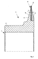
- Fig. 1 is a cross-section through a first embodiment according to the invention of a tool for working surfaces according to the present invention is shown.
- the tool 1 comprises a receiving device, which is composed of a spindle 2 and a fixing flange 3.
- the spindle has an axial opening 7, which serves for receiving in a corresponding machine tool.
- a machining disk 4 is inserted between the oblique sections 8 of the spindle and the fixing flange 3.
- the machining disk 4 consists of a base body 6 and, according to the embodiment shown here, a rectangular machining surface 5, which essentially consists of a carrier material and the grinding bodies fixed thereto or here.
- the processing surface 5 according to the embodiment shown here has a rectangular cross-section, whereby it is of course also within the meaning of the present invention that this area is adapted according to the surface structure of the workpiece to be machined and in particular rounded or tapered or the like can be performed.
- the tool 1 of the embodiment shown in Fig. 1 is made of, for example, a material which is particularly metal such as 11Sn30 steel, St37, C15, bronze, bronze alloys, aluminum, stainless steel, plastic, ceramic, composite, combinations thereof, or the like ,
- FIG. 2 shows a machining disk according to a preferred embodiment, in which the opening 10 can be seen, which serves to push the disk onto the spindle 2. Furthermore, the main body 6 of the machining disk and, according to the embodiment shown here, to recognize the working surface, wherein on the outer periphery diamond needles are used. Such diamond needles are preferably already bonded firmly to the base material during sintering of the machining disk and, after being assembled with the mounting device, are machined to provide, in particular, a profile in the machining area that corresponds to the desired shapes for machining a workpiece.
- FIG. 3 is a side view of the machining disk of FIG. 2 in an enlarged view, wherein substantially the base material of the machining disk and the opening 10 can be seen.
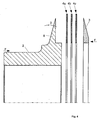
- FIG. 4 is a schematic sectional view of another particularly preferred embodiment of the present invention in an exploded view, in which, for example, three processing disks 4, 4b, 4c are placed on the spindle 2 instead of a single processing disk. In this case, they are completed on the right side according to the previously illustrated embodiment of FIG. 1 by means of a Fixierflansches 3.
- the machining discs 4 a, 4 b and 4 c prior to assembly on the receiving device are wetted, for example, with solder before assembly and then mounted on the spindle, aligned and finished right-justified by the Fixierflansch 3.
- a temperature is selected for fixing the machining disks with each other and for fixing the machining disks with the receiving device, in which a uniform distribution of the liquid solder is ensured especially in combination with flux and at the fixed or clamped during the curing process, in particular the outer regions of the spindle and the Fixierflansches (arrows F) to ensure a defined position of the processing discs to each other and to the receiving device.
- the processing discs are present as a raw form prior to assembly and are brought into a desired shape only after the curing of the bonding agent.
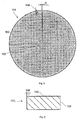
- FIG. 5 shows a plan view of a base body, as can be used in the method according to the invention for producing a form roller.
- a base body has, as shown in FIG. 5, a profiling 102 which extends from the center 103 up to a predetermined distance 104 to the outer diameter.
- the profile can be chosen almost freely, the arranged around the center of rotation 103 mass distribution of the base body thus generated should be as homogeneous as possible, thereby causing vibrations in the inter alia from the As far as possible to reduce or avoid moldings produced basic bodies.
- the profiling is chosen in such a way that, in particular after sintering of the alloy matrix, an intimate bond is formed, which can be improved inter alia by the application of a coating such as a tin layer.
- the profiling is the requirement that it provides a surface which is as uniform and finely structured as possible, which interrelates over a coating or also directly with the alloy matrix.
- the profiling can be introduced, for example in the form of a spiral on the front side of the base body, wherein according to the embodiment shown in Fig. 5, the outer region 104 has no profiling.
- the machining bodies such as, for example, CVD, diamond needles are preferably arranged, which are preferably positioned with an industrial adhesive on the surface of the base body.
- the arrangement takes place in particular when using CVD diamond needles 116 with a predetermined distance, which is determined on the one hand by the outer periphery of the base 101 and the number of processing body 116 and thus an angular displacement of the processing body 116 over the outer region of the body with a predetermined angle ⁇ results.
- FIG. 6 shows the basic body from FIG. 5 in a radial partial sectional view, in which, starting from the center line 103 on the upper side, the profiling 102 and the unprofiled outer region 104 can be seen. It is clear that the profiling essentially in the superficial region of the body 101 is present, according to a particularly preferred embodiment of the present invention, the profiling depth between 0.001 and 0.5 mm and in particular about 0.2 mm.
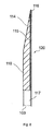
- FIG. 7 shows a first exemplary embodiment of a finished diamond forming roll, in which a first main body 110 and a second main body 111 enclose the alloy matrix 115 and at the peripheral region of which the processing bodies 116, such as, for example, CVD diamond needles, are arranged.
- a passage 117 is arranged, which serves in particular for receiving the forming roller in a corresponding processing device.
- the forming roller is constructed substantially symmetrically, and in the outer region has a substantially conically tapering thickness 114, which is applied by, for example, machining the base body or parts of the alloy matrix.
- form rollers according to the invention can of course also have any other geometric shape, in particular with regard to their radial thickness profile, as they are usually required in the corresponding area.
- a particularly advantageous embodiment of a forming roller 120 since an intimate connection between the two basic bodies 110, 111 is provided by the alloy matrix 115 and, if appropriate, the coating applied correspondingly to the surfaces of the basic body facing it.
- This connection is in particular designed such that a separation of the layers is avoided even at high processing speeds, with which the forming rollers according to the invention are used.
- the arrangement according to the invention of the alloy matrix with respect to the machining bodies, such as the CVD diamond needles provides an intimate connection therebetween which, in addition to precise alignment of the machining bodies, also provides the highly resistant fixings of these machining bodies.
- FIG. 8 shows a second exemplary embodiment of a finished diamond forming roll, in which the alloy matrix 115 is directly on the first base body 110 is arranged and wherein at its peripheral region, the processing body 116, such as CVD diamond needles, are arranged.
- the alloy matrix is not covered by a second base body, which, without being detrimental to the stability of the form roller according to the invention, allows a further simplification of the production of such form rollers.
- a passage 117 is arranged, which serves in particular for receiving the forming roller in a corresponding processing device.
- the forming roller is constructed asymmetrically, but in the outer region it also has a substantially conically tapering thickness 114, which is attached by an example of a machining of the main body or parts of the alloy matrix.
- form rollers according to this embodiment of the invention can of course also have any other geometric shape, in particular with regard to their radial thickness profile, as is usually required in the corresponding area.
- a particularly advantageous embodiment of a forming roller 120 also results, since an intimate connection between the base body 110 and the alloy matrix 115 is possibly provided for the coating applied correspondingly to the surfaces of the base body facing it.
- This connection is in particular designed such that a separation of the layers is avoided even at high processing speeds, with which the forming rollers according to the invention are used.
- the arrangement according to the invention of the alloy matrix with respect to the machining bodies, such as the CVD diamond needles provides an intimate connection therebetween which, in addition to precise alignment of the machining bodies, also provides the highly resistant fixings of these machining bodies.
- the base body or bodies After sawing off at least one, preferably two base bodies, which consist for example of free-cutting steel, the base body or bodies are rotated cylindrically in accordance with a specification. At least one end face of the main body or the base body, a profile, for example, similar to a metric thread, pierced. The profile preferably extends on the front side to the outside and extends almost over the entire diameter. Subsequent to the profiling, the base body is coated on the profiled surface with, for example, a liquid tin layer, which combines with the material of the main body as a result of the rapid cooling.
- a liquid tin layer which combines with the material of the main body as a result of the rapid cooling.
- the coating is carried out at a maximum processing temperature of 300 ° C, wherein in particular after cooling the corresponding coated base body or the corresponding coated base body, the coated surface or the coated surfaces cleaned with, for example, a wire brush and the remaining surfaces with a Emery or emery paper of grain 120 are polished.
- the base body or bodies prepared in this way are assembled into a shape in such a way that an outer ring, which consists for example of NIMONIC metal and which is coated in particular with graphite on its inner circumferential surface, is placed around a base body and optionally braced, wherein the Profiling of the body facing up.
- the outer ring whose thickness is greater than that of the base body, and the profiled surface of the base body, a disc-shaped cavity in which, for example, CVD diamond needles are set according to a fixed scheme.
- the needles lie on the profiled surface on the outer diameter of the base body and touch the inside of the outer ring.
- the diamond needles are firmly bonded, for example with a construction adhesive on the body.
- the thus prepared mold is filled with an alloy matrix, for example of CuSn, wherein the alloy matrix is preferably interspersed in powder form and is distributed flat and planar within the cavity between the outer ring and the base body, for example by peeling.
- a press shoe or a pressure plate is placed on the alloy matrix and applied in a suitable press a cold pressure over a predefined period of time, so that the alloy matrix is compacted.
- a second base body is inserted into the outer ring with its profiled surface facing towards the alloy matrix.
- the thus assembled shape is exposed from the side of the second base body of a defined cold pressure, so that in particular the alloy matrix is compacted.
- pressures of 50 to 1000 tons, including all values lying between these limits, are applied to the alloy matrix or the mold, wherein the pressure is optionally modulated in time.
- the complete mold if appropriate while maintaining the pressure on the alloy matrix or the mold, is introduced into a sintering furnace whose sintering temperature is approximately 740 ° C., the holding temperature for example for the sintering process being approximately 5 minutes.
- a predetermined hot pressure is applied to the alloy matrix or external body and the alloy matrix therebetween to assure that the body and alloy matrix and the like are in contact with each other. a. connect together as completely as possible during cooling.
- the outer ring is removed from the main body or the basic bodies and the tool joint containing the joint connection, which consists of the basic bodies and the alloy matrix, is machined to specification in order to make the finished tool available.
- Chip machining involves turning and grinding the tool blank. Upon completion of this machining process, the forming roll measured and tested and can be used for the treatment of surfaces.
Landscapes
- Engineering & Computer Science (AREA)
- Mechanical Engineering (AREA)
- Manufacturing & Machinery (AREA)
- Polishing Bodies And Polishing Tools (AREA)
- Cutting Tools, Boring Holders, And Turrets (AREA)
- Turning (AREA)
- Shaping Metal By Deep-Drawing, Or The Like (AREA)
Applications Claiming Priority (2)
| Application Number | Priority Date | Filing Date | Title |
|---|---|---|---|
| DE102006012926A DE102006012926A1 (de) | 2006-03-21 | 2006-03-21 | Werkzeug zum Bearbeiten von Oberflächen und Verfahren zur Herstellung eines solchen Werkzeugs |
| DE200610039768 DE102006039768A1 (de) | 2006-08-24 | 2006-08-24 | Verfahren zur Herstellung einer Formrolle |
Publications (2)
| Publication Number | Publication Date |
|---|---|
| EP1837123A1 true EP1837123A1 (fr) | 2007-09-26 |
| EP1837123B1 EP1837123B1 (fr) | 2010-08-18 |
Family
ID=38122346
Family Applications (1)
| Application Number | Title | Priority Date | Filing Date |
|---|---|---|---|
| EP06127136A Not-in-force EP1837123B1 (fr) | 2006-03-21 | 2006-12-22 | Outil destiné au traitement de surfaces et son procédé de fabrication |
Country Status (3)
| Country | Link |
|---|---|
| EP (1) | EP1837123B1 (fr) |
| AT (1) | ATE477887T1 (fr) |
| DE (1) | DE502006007682D1 (fr) |
Cited By (3)
| Publication number | Priority date | Publication date | Assignee | Title |
|---|---|---|---|---|
| DE102010000921A1 (de) | 2009-01-15 | 2010-07-29 | Bernd Kuntz | Abrichtwerkzeug und Verfahren zu dessen Herstellung |
| WO2015024892A1 (fr) * | 2013-08-19 | 2015-02-26 | Saint-Gobain Diamantwerkzeuge Gmbh & Co. Kg | Rouleau de dressage |
| CN111113286A (zh) * | 2020-01-13 | 2020-05-08 | 宋京新 | 一种电镀钢丝齿拼合式杯形砂轮 |
Citations (3)
| Publication number | Priority date | Publication date | Assignee | Title |
|---|---|---|---|---|
| DE29605728U1 (de) * | 1996-03-28 | 1996-09-05 | C. & E. Fein Gmbh & Co, 70176 Stuttgart | Sägeblatt |
| EP0922533A2 (fr) * | 1997-12-09 | 1999-06-16 | ERNST WINTER & SOHN Diamantwerkzeuge GmbH & Co. | Molette de dressage pour meules de rectification |
| DE202004009761U1 (de) * | 2003-08-20 | 2004-08-12 | Tyrolit-Schleifmittelwerke Swarovski Kg, Schwaz | Trenn- oder Schleifscheibe |
-
2006
- 2006-12-22 DE DE502006007682T patent/DE502006007682D1/de active Active
- 2006-12-22 AT AT06127136T patent/ATE477887T1/de active
- 2006-12-22 EP EP06127136A patent/EP1837123B1/fr not_active Not-in-force
Patent Citations (4)
| Publication number | Priority date | Publication date | Assignee | Title |
|---|---|---|---|---|
| DE29605728U1 (de) * | 1996-03-28 | 1996-09-05 | C. & E. Fein Gmbh & Co, 70176 Stuttgart | Sägeblatt |
| EP0922533A2 (fr) * | 1997-12-09 | 1999-06-16 | ERNST WINTER & SOHN Diamantwerkzeuge GmbH & Co. | Molette de dressage pour meules de rectification |
| DE19754517A1 (de) * | 1997-12-09 | 1999-06-17 | Winter & Sohn Ernst | Abrichtrolle für Schleifscheiben |
| DE202004009761U1 (de) * | 2003-08-20 | 2004-08-12 | Tyrolit-Schleifmittelwerke Swarovski Kg, Schwaz | Trenn- oder Schleifscheibe |
Cited By (4)
| Publication number | Priority date | Publication date | Assignee | Title |
|---|---|---|---|---|
| DE102010000921A1 (de) | 2009-01-15 | 2010-07-29 | Bernd Kuntz | Abrichtwerkzeug und Verfahren zu dessen Herstellung |
| WO2015024892A1 (fr) * | 2013-08-19 | 2015-02-26 | Saint-Gobain Diamantwerkzeuge Gmbh & Co. Kg | Rouleau de dressage |
| US9956665B2 (en) | 2013-08-19 | 2018-05-01 | Saint-Gobain Diamantwerkzeuge Gmbh | Form dressing roller |
| CN111113286A (zh) * | 2020-01-13 | 2020-05-08 | 宋京新 | 一种电镀钢丝齿拼合式杯形砂轮 |
Also Published As
| Publication number | Publication date |
|---|---|
| EP1837123B1 (fr) | 2010-08-18 |
| DE502006007682D1 (de) | 2010-09-30 |
| ATE477887T1 (de) | 2010-09-15 |
Similar Documents
| Publication | Publication Date | Title |
|---|---|---|
| DE3316650C2 (fr) | ||
| EP3898039B1 (fr) | Procédé de fabrication d'une pièce verte | |
| DE1502642A1 (de) | Diamantformwerkzeug | |
| DE4412010C2 (de) | Vorrichtung zum sphärischen Hochglanzschleifen | |
| DE102016112819A1 (de) | Schleifrad | |
| EP2956271A1 (fr) | Procédé et outil de rectification pour la rectification sans centre haute précision d'éléments de type arbre, à un haut niveau de qualité de surface | |
| EP4171848B1 (fr) | Procédé de fabrication d'une ébauche et procédé de traitement ultérieur de l'ébauche en un segment de traitement | |
| EP4171878B1 (fr) | Procédé de fabrication d'une ébauche et procédé de traitement ultérieur de l'ébauche en un segment de traitement | |
| EP1837123B1 (fr) | Outil destiné au traitement de surfaces et son procédé de fabrication | |
| EP3036063B1 (fr) | Rouleau de dressage | |
| DE102010025677A1 (de) | Abrichtwerkzeug | |
| EP4171865A1 (fr) | Procédé de fabrication d'un segment d'usinage comportant une partie de particules de matériau dur faisant saillie sur les faces latérales du segment d'usinage | |
| DE3623408A1 (de) | Schleifwerkzeug, insbesondere schleifstift | |
| EP3219439B1 (fr) | Meule | |
| AT515475B1 (de) | Herstellung einer Topfscheibe | |
| DE102006012926A1 (de) | Werkzeug zum Bearbeiten von Oberflächen und Verfahren zur Herstellung eines solchen Werkzeugs | |
| EP0606635A1 (fr) | Procédé de fabrication d'outils de meulage et outil ainsi réalisé | |
| EP3659748A1 (fr) | Corps support pour un outil de meulage ou de coupe | |
| DE102006039768A1 (de) | Verfahren zur Herstellung einer Formrolle | |
| DE4447036C2 (de) | Werkzeug zur Oberflächenbearbeitung von Werkstücken | |
| DE4300417A1 (de) | Grundkörper für Schleifscheiben für rotierende oder schwingende Schleifwerkzeuge | |
| DE3138163C2 (fr) | ||
| AT526783B1 (de) | Schleifwerkzeug | |
| AT524212B1 (de) | Verfahren zur Herstellung einer Reiblamelle | |
| DE202017104133U1 (de) | Trennscheibe zur Erzeugung gekrümmter Trennschnitte und Vorrichtung zur Herstellung einer Trennscheibe |
Legal Events
| Date | Code | Title | Description |
|---|---|---|---|
| PUAI | Public reference made under article 153(3) epc to a published international application that has entered the european phase |
Free format text: ORIGINAL CODE: 0009012 |
|
| AK | Designated contracting states |
Kind code of ref document: A1 Designated state(s): AT BE BG CH CY CZ DE DK EE ES FI FR GB GR HU IE IS IT LI LT LU LV MC NL PL PT RO SE SI SK TR |
|
| AX | Request for extension of the european patent |
Extension state: AL BA HR MK YU |
|
| 17P | Request for examination filed |
Effective date: 20080131 |
|
| 17Q | First examination report despatched |
Effective date: 20080317 |
|
| AKX | Designation fees paid |
Designated state(s): AT BE BG CH CY CZ DE DK EE ES FI FR GB GR HU IE IS IT LI LT LU LV MC NL PL PT RO SE SI SK TR |
|
| RAP1 | Party data changed (applicant data changed or rights of an application transferred) |
Owner name: DR. MUELLER DIAMANTMETALL AG |
|
| RAP1 | Party data changed (applicant data changed or rights of an application transferred) |
Owner name: DR. MUELLER DIAMANTMETALL AG |
|
| GRAP | Despatch of communication of intention to grant a patent |
Free format text: ORIGINAL CODE: EPIDOSNIGR1 |
|
| GRAS | Grant fee paid |
Free format text: ORIGINAL CODE: EPIDOSNIGR3 |
|
| GRAA | (expected) grant |
Free format text: ORIGINAL CODE: 0009210 |
|
| AK | Designated contracting states |
Kind code of ref document: B1 Designated state(s): AT BE BG CH CY CZ DE DK EE ES FI FR GB GR HU IE IS IT LI LT LU LV MC NL PL PT RO SE SI SK TR |
|
| REG | Reference to a national code |
Ref country code: GB Ref legal event code: FG4D Free format text: NOT ENGLISH |
|
| REG | Reference to a national code |
Ref country code: CH Ref legal event code: EP |
|
| REG | Reference to a national code |
Ref country code: IE Ref legal event code: FG4D Free format text: LANGUAGE OF EP DOCUMENT: GERMAN |
|
| REF | Corresponds to: |
Ref document number: 502006007682 Country of ref document: DE Date of ref document: 20100930 Kind code of ref document: P |
|
| REG | Reference to a national code |
Ref country code: NL Ref legal event code: VDEP Effective date: 20100818 |
|
| LTIE | Lt: invalidation of european patent or patent extension |
Effective date: 20100818 |
|
| PG25 | Lapsed in a contracting state [announced via postgrant information from national office to epo] |
Ref country code: LT Free format text: LAPSE BECAUSE OF FAILURE TO SUBMIT A TRANSLATION OF THE DESCRIPTION OR TO PAY THE FEE WITHIN THE PRESCRIBED TIME-LIMIT Effective date: 20100818 Ref country code: FI Free format text: LAPSE BECAUSE OF FAILURE TO SUBMIT A TRANSLATION OF THE DESCRIPTION OR TO PAY THE FEE WITHIN THE PRESCRIBED TIME-LIMIT Effective date: 20100818 |
|
| PG25 | Lapsed in a contracting state [announced via postgrant information from national office to epo] |
Ref country code: CY Free format text: LAPSE BECAUSE OF FAILURE TO SUBMIT A TRANSLATION OF THE DESCRIPTION OR TO PAY THE FEE WITHIN THE PRESCRIBED TIME-LIMIT Effective date: 20100818 Ref country code: PT Free format text: LAPSE BECAUSE OF FAILURE TO SUBMIT A TRANSLATION OF THE DESCRIPTION OR TO PAY THE FEE WITHIN THE PRESCRIBED TIME-LIMIT Effective date: 20101220 Ref country code: SI Free format text: LAPSE BECAUSE OF FAILURE TO SUBMIT A TRANSLATION OF THE DESCRIPTION OR TO PAY THE FEE WITHIN THE PRESCRIBED TIME-LIMIT Effective date: 20100818 Ref country code: PL Free format text: LAPSE BECAUSE OF FAILURE TO SUBMIT A TRANSLATION OF THE DESCRIPTION OR TO PAY THE FEE WITHIN THE PRESCRIBED TIME-LIMIT Effective date: 20100818 Ref country code: IS Free format text: LAPSE BECAUSE OF FAILURE TO SUBMIT A TRANSLATION OF THE DESCRIPTION OR TO PAY THE FEE WITHIN THE PRESCRIBED TIME-LIMIT Effective date: 20101218 Ref country code: BG Free format text: LAPSE BECAUSE OF FAILURE TO SUBMIT A TRANSLATION OF THE DESCRIPTION OR TO PAY THE FEE WITHIN THE PRESCRIBED TIME-LIMIT Effective date: 20101118 |
|
| REG | Reference to a national code |
Ref country code: IE Ref legal event code: FD4D |
|
| PG25 | Lapsed in a contracting state [announced via postgrant information from national office to epo] |
Ref country code: LV Free format text: LAPSE BECAUSE OF FAILURE TO SUBMIT A TRANSLATION OF THE DESCRIPTION OR TO PAY THE FEE WITHIN THE PRESCRIBED TIME-LIMIT Effective date: 20100818 Ref country code: GR Free format text: LAPSE BECAUSE OF FAILURE TO SUBMIT A TRANSLATION OF THE DESCRIPTION OR TO PAY THE FEE WITHIN THE PRESCRIBED TIME-LIMIT Effective date: 20101119 Ref country code: NL Free format text: LAPSE BECAUSE OF FAILURE TO SUBMIT A TRANSLATION OF THE DESCRIPTION OR TO PAY THE FEE WITHIN THE PRESCRIBED TIME-LIMIT Effective date: 20100818 Ref country code: SE Free format text: LAPSE BECAUSE OF FAILURE TO SUBMIT A TRANSLATION OF THE DESCRIPTION OR TO PAY THE FEE WITHIN THE PRESCRIBED TIME-LIMIT Effective date: 20100818 |
|
| PG25 | Lapsed in a contracting state [announced via postgrant information from national office to epo] |
Ref country code: IE Free format text: LAPSE BECAUSE OF FAILURE TO SUBMIT A TRANSLATION OF THE DESCRIPTION OR TO PAY THE FEE WITHIN THE PRESCRIBED TIME-LIMIT Effective date: 20100818 Ref country code: DK Free format text: LAPSE BECAUSE OF FAILURE TO SUBMIT A TRANSLATION OF THE DESCRIPTION OR TO PAY THE FEE WITHIN THE PRESCRIBED TIME-LIMIT Effective date: 20100818 |
|
| PG25 | Lapsed in a contracting state [announced via postgrant information from national office to epo] |
Ref country code: EE Free format text: LAPSE BECAUSE OF FAILURE TO SUBMIT A TRANSLATION OF THE DESCRIPTION OR TO PAY THE FEE WITHIN THE PRESCRIBED TIME-LIMIT Effective date: 20100818 Ref country code: CZ Free format text: LAPSE BECAUSE OF FAILURE TO SUBMIT A TRANSLATION OF THE DESCRIPTION OR TO PAY THE FEE WITHIN THE PRESCRIBED TIME-LIMIT Effective date: 20100818 Ref country code: RO Free format text: LAPSE BECAUSE OF FAILURE TO SUBMIT A TRANSLATION OF THE DESCRIPTION OR TO PAY THE FEE WITHIN THE PRESCRIBED TIME-LIMIT Effective date: 20100818 Ref country code: IT Free format text: LAPSE BECAUSE OF FAILURE TO SUBMIT A TRANSLATION OF THE DESCRIPTION OR TO PAY THE FEE WITHIN THE PRESCRIBED TIME-LIMIT Effective date: 20100818 Ref country code: SK Free format text: LAPSE BECAUSE OF FAILURE TO SUBMIT A TRANSLATION OF THE DESCRIPTION OR TO PAY THE FEE WITHIN THE PRESCRIBED TIME-LIMIT Effective date: 20100818 |
|
| PLBE | No opposition filed within time limit |
Free format text: ORIGINAL CODE: 0009261 |
|
| STAA | Information on the status of an ep patent application or granted ep patent |
Free format text: STATUS: NO OPPOSITION FILED WITHIN TIME LIMIT |
|
| BERE | Be: lapsed |
Owner name: DR. MULLER DIAMANTMETALL A.G. Effective date: 20101231 |
|
| PG25 | Lapsed in a contracting state [announced via postgrant information from national office to epo] |
Ref country code: ES Free format text: LAPSE BECAUSE OF FAILURE TO SUBMIT A TRANSLATION OF THE DESCRIPTION OR TO PAY THE FEE WITHIN THE PRESCRIBED TIME-LIMIT Effective date: 20101129 |
|
| 26N | No opposition filed |
Effective date: 20110519 |
|
| PG25 | Lapsed in a contracting state [announced via postgrant information from national office to epo] |
Ref country code: MC Free format text: LAPSE BECAUSE OF NON-PAYMENT OF DUE FEES Effective date: 20101231 |
|
| GBPC | Gb: european patent ceased through non-payment of renewal fee |
Effective date: 20101222 |
|
| REG | Reference to a national code |
Ref country code: DE Ref legal event code: R097 Ref document number: 502006007682 Country of ref document: DE Effective date: 20110519 |
|
| REG | Reference to a national code |
Ref country code: FR Ref legal event code: ST Effective date: 20110831 |
|
| PG25 | Lapsed in a contracting state [announced via postgrant information from national office to epo] |
Ref country code: BE Free format text: LAPSE BECAUSE OF NON-PAYMENT OF DUE FEES Effective date: 20101231 |
|
| PG25 | Lapsed in a contracting state [announced via postgrant information from national office to epo] |
Ref country code: FR Free format text: LAPSE BECAUSE OF NON-PAYMENT OF DUE FEES Effective date: 20110103 |
|
| PG25 | Lapsed in a contracting state [announced via postgrant information from national office to epo] |
Ref country code: GB Free format text: LAPSE BECAUSE OF NON-PAYMENT OF DUE FEES Effective date: 20101222 |
|
| PG25 | Lapsed in a contracting state [announced via postgrant information from national office to epo] |
Ref country code: LU Free format text: LAPSE BECAUSE OF NON-PAYMENT OF DUE FEES Effective date: 20101222 Ref country code: HU Free format text: LAPSE BECAUSE OF FAILURE TO SUBMIT A TRANSLATION OF THE DESCRIPTION OR TO PAY THE FEE WITHIN THE PRESCRIBED TIME-LIMIT Effective date: 20110219 |
|
| PG25 | Lapsed in a contracting state [announced via postgrant information from national office to epo] |
Ref country code: TR Free format text: LAPSE BECAUSE OF FAILURE TO SUBMIT A TRANSLATION OF THE DESCRIPTION OR TO PAY THE FEE WITHIN THE PRESCRIBED TIME-LIMIT Effective date: 20100818 |
|
| PGFP | Annual fee paid to national office [announced via postgrant information from national office to epo] |
Ref country code: AT Payment date: 20130103 Year of fee payment: 7 |
|
| PGFP | Annual fee paid to national office [announced via postgrant information from national office to epo] |
Ref country code: CH Payment date: 20130103 Year of fee payment: 7 |
|
| REG | Reference to a national code |
Ref country code: CH Ref legal event code: PL |
|
| REG | Reference to a national code |
Ref country code: AT Ref legal event code: MM01 Ref document number: 477887 Country of ref document: AT Kind code of ref document: T Effective date: 20131222 |
|
| PG25 | Lapsed in a contracting state [announced via postgrant information from national office to epo] |
Ref country code: CH Free format text: LAPSE BECAUSE OF NON-PAYMENT OF DUE FEES Effective date: 20131231 Ref country code: LI Free format text: LAPSE BECAUSE OF NON-PAYMENT OF DUE FEES Effective date: 20131231 |
|
| PG25 | Lapsed in a contracting state [announced via postgrant information from national office to epo] |
Ref country code: AT Free format text: LAPSE BECAUSE OF NON-PAYMENT OF DUE FEES Effective date: 20131222 |
|
| PGFP | Annual fee paid to national office [announced via postgrant information from national office to epo] |
Ref country code: DE Payment date: 20211206 Year of fee payment: 16 |
|
| REG | Reference to a national code |
Ref country code: DE Ref legal event code: R119 Ref document number: 502006007682 Country of ref document: DE |
|
| PG25 | Lapsed in a contracting state [announced via postgrant information from national office to epo] |
Ref country code: DE Free format text: LAPSE BECAUSE OF NON-PAYMENT OF DUE FEES Effective date: 20230701 |