EP1837189A2 - Dispositif pour affiner des pièces à fabriquer - Google Patents
Dispositif pour affiner des pièces à fabriquer Download PDFInfo
- Publication number
- EP1837189A2 EP1837189A2 EP06017766A EP06017766A EP1837189A2 EP 1837189 A2 EP1837189 A2 EP 1837189A2 EP 06017766 A EP06017766 A EP 06017766A EP 06017766 A EP06017766 A EP 06017766A EP 1837189 A2 EP1837189 A2 EP 1837189A2
- Authority
- EP
- European Patent Office
- Prior art keywords
- workpiece
- printing
- spindle unit
- printing unit
- ink
- Prior art date
- Legal status (The legal status is an assumption and is not a legal conclusion. Google has not performed a legal analysis and makes no representation as to the accuracy of the status listed.)
- Granted
Links
Images



Classifications
-
- B—PERFORMING OPERATIONS; TRANSPORTING
- B41—PRINTING; LINING MACHINES; TYPEWRITERS; STAMPS
- B41J—TYPEWRITERS; SELECTIVE PRINTING MECHANISMS, i.e. MECHANISMS PRINTING OTHERWISE THAN FROM A FORME; CORRECTION OF TYPOGRAPHICAL ERRORS
- B41J3/00—Typewriters or selective printing or marking mechanisms characterised by the purpose for which they are constructed
- B41J3/407—Typewriters or selective printing or marking mechanisms characterised by the purpose for which they are constructed for marking on special material
-
- B—PERFORMING OPERATIONS; TRANSPORTING
- B41—PRINTING; LINING MACHINES; TYPEWRITERS; STAMPS
- B41J—TYPEWRITERS; SELECTIVE PRINTING MECHANISMS, i.e. MECHANISMS PRINTING OTHERWISE THAN FROM A FORME; CORRECTION OF TYPOGRAPHICAL ERRORS
- B41J3/00—Typewriters or selective printing or marking mechanisms characterised by the purpose for which they are constructed
- B41J3/28—Typewriters or selective printing or marking mechanisms characterised by the purpose for which they are constructed for printing downwardly on flat surfaces, e.g. of books, drawings, boxes, envelopes, e.g. flat-bed ink-jet printers
-
- B—PERFORMING OPERATIONS; TRANSPORTING
- B41—PRINTING; LINING MACHINES; TYPEWRITERS; STAMPS
- B41J—TYPEWRITERS; SELECTIVE PRINTING MECHANISMS, i.e. MECHANISMS PRINTING OTHERWISE THAN FROM A FORME; CORRECTION OF TYPOGRAPHICAL ERRORS
- B41J3/00—Typewriters or selective printing or marking mechanisms characterised by the purpose for which they are constructed
- B41J3/44—Typewriters or selective printing mechanisms having dual functions or combined with, or coupled to, apparatus performing other functions
Definitions
- the invention relates to a device for refining workpieces, which are preferably at least partially made of wood, wood-based materials or the like, according to the preamble of claim 1.
- a device of the type mentioned is, for example, from the DE 100 31 030 B4 known.
- workpieces are delivered and stored on a conveyor.
- the apparatus In order to detect the positioning of the workpieces on the conveyor, the apparatus has stationary sensors mounted on the conveyor or on a gantry. These sensors must also detect the geometry of the workpieces, or the geometry data must be transferred from an upstream processing machine and read and transformed by the sensors taking into account the new positioning data. This leads to a high constructive and procedural effort.
- the invention is based on the idea to avoid the re-clamping of the workpieces to be finished in the course of finishing as much as possible.
- it is provided according to the invention in a generic device that it further comprises at least one processing device for processing the workpiece.
- it is possible not only to print the workpieces in the device according to the invention, but also to carry out individual or numerous machining operations, which can be before, after or even temporarily stored for printing.
- individual or numerous machining operations which can be before, after or even temporarily stored for printing.
- can be dispensed with a re-clamping between these finishing steps so that no multiple workpiece alignment and / or sensor detection is required, which simplifies the construction of the overall device and its operation, without affecting the finishing quality.
- the ink-jet printing device and / or the processing device stationary and to be finished workpieces feed this along using the conveyor along. It is likewise possible to make the printing device and / or the machining device movable or to provide a combination of both variants, ie that both the workpieces and the printing device and / or the machining device are moved during the printing or machining operation using the conveying device ,
- the processing device for processing the workpiece can be configured in a wide variety of ways and designed for one or more types of processing.
- the machining operations for which the processing apparatus is set up are selected, for example, from at least one of machining Machining, edgebanding, extrusion, coating, laminating, cleaning, degreasing, improving the adhesion and wetting properties and reducing the electrostatic charge.
- machining Machining, edgebanding, extrusion, coating, laminating, cleaning, degreasing, improving the adhesion and wetting properties and reducing the electrostatic charge is applied to the filed by the Applicant European patent application with the No. 06 004 713.1 whose priority is claimed.
- other types of processing may also be used in the context of the invention, in particular those for preparing and / or post-treating the workpiece to be printed or printed.
- the conveying device can be configured in various ways in the context of the present invention be, for example by a single workpiece conveyor table, but also by a plurality of movable components that can be moved in relation to each other. According to one embodiment of the invention, however, it is preferred that the conveying device is set up to bring about a relative movement between the workpiece to be finished and the processing device, preferably in such a way that the workpiece can be processed and printed without changing its relative position to the workpiece carrier device. In this way, a re-clamping of the workpieces to be finished in the course of finishing in the device according to the invention can be avoided, resulting in a simple and precise operation with high quality finishing.
- the ink-jet printing device and the processing device can in principle be placed anywhere in the device according to the invention, for example also on a movable or stationary robot. They can also be fixed.
- the at least one bar-like guide device for the printing device and / or the processing device has, in particular a portal or a boom. In this way, this printing device or the processing device can be easily positioned at a desired location and beyond, if necessary, be moved along the bar-like guide device.
- the bar-like guide device can advantageously serve to receive a spindle unit provided according to an embodiment of the invention, wherein the spindle unit is preferably movable on the bar-like guide device and / or preferably pivotable about at least one axis.
- Such a spindle unit is very well suited as a basic component of a processing device, in particular in combination with a plurality of Machining tools and / or assemblies, which are preferably exchangeable in the at least one spindle unit and particularly preferably stored in at least one magazine. This results in low design effort, such as a small number of drives, a wide variety of processing options for the workpieces.
- the at least one spindle unit can be used not only for operating a wide variety of machining tools and / or assemblies, but also for operating a printing unit.
- a printing unit is provided, which is exchangeable in the at least one spindle unit, in particular via an interface.
- the printing unit can also be used flexibly and only brought into an operating position in the spindle unit when it is needed for finishing the workpiece.
- the printing unit has connection means by means of which it can be exchanged into the tool-holder of a spindle unit.
- the spindle unit does not have to be adapted to accommodate the printing unit, but the printing unit has suitable connection means which can be included in the already existing tool holder of the spindle unit.
- such a replaceable printing unit also has transmission means which are set up to communicate with transmission means of an interface of the respective spindle unit.
- transmission means which are set up to communicate with transmission means of an interface of the respective spindle unit.
- the transmission means are set up to receive at least data and / or energy and / or ink from the transmission means of the spindle unit.
- the printing unit has an ink supply.
- the operation of the printing unit can be made more independent of an ink supply and thus faster and more reliable.
- the printing unit is supplied with ink from the outside or via an interface of a spindle unit, for example by the ink supply of the printing unit is filled at regular intervals or continuously from the outside or via the interface.
- the printing unit can be set up according to an embodiment of the invention for the wireless data transmission from and / or to a control device. This results, analogous to the above, a simple construction and a trouble-free operation of the printing unit according to the invention and the device according to the invention.
- the printing unit further comprises at least one sensor, in particular at least one distance sensor and / or at least one image detection sensor.
- At least one sensor in particular at least one distance sensor and / or at least one image detection sensor.
- the present invention provides a method for refining workpieces using a device according to the invention, which is characterized in that the respective workpiece is processed and printed while maintaining a predetermined relative position to the workpiece support means.
- a device 1 for refining workpieces as a preferred embodiment of the present invention is shown schematically in Fig. 1 in a perspective view.
- the device is used for processing and patterning of workpieces 2, which in the present embodiment at least partially made of wood, wood materials, plastics or the like, as they are often used for example in the field of furniture and components.
- the device 1 comprises an ink-jet printing device 10, which operates in the present embodiment according to the drop-on-demand principle.
- the ink-jet printing apparatus 10 includes a plurality of nozzles 12 from which ink droplets may be ejected and which are arranged in a plurality of rows in the present embodiment, each row for ejecting a predetermined one Color is provided, for example, the colors cyan, magenta, yellow and black.
- drying units 14, for example UV dryers are provided on the printing device 10, which serve to rapidly increase the ink applied by the printing device dry to prevent possible printing with inaccurate "passer".
- the printing device 10 is provided in the present embodiment on a spindle unit 6 or in this changed, which is best seen in Fig. 3.
- the spindle unit is preferably such a spindle unit which is also suitable for receiving and exchangeable receiving machining tools or processing units and for this purpose a tool holder 6 'and an interface 6 ", wherein the interface, for example, for the transmission of data , Energy, drive, fluids, etc. may be designed.
- the printing unit 10 is provided in the present embodiment with a connecting piece 18 which is ein anbar in the tool holder 6 'of the spindle unit (see Fig .. 3). Furthermore, the printing unit 10 has transmission means 16 (see Fig. 3) which can communicate with the interface 6 "of the spindle unit, whereby data, energy, drive, fluids, etc. and in particular also ink can be transmitted Printing unit 10 have an ink supply and / or a wireless data transmission device, although this is not shown in the figures.
- the spindle unit 6 is provided in the y-direction movable on a portal 4, which in turn can be designed to be movable in the x-direction.
- a portal 4 which in turn can be designed to be movable in the x-direction.
- two portals 4 are provided in the present embodiment, each of which may carry one or more spindle units 6, which may optionally be arranged on opposite sides of the respective portal 4. It should be noted that the portals 4 may optionally be designed as a boom.
- the spindle units 6 can be automatically or manually equipped with processing tools and / or processing units 30 and one or more printing units 10 via tool magazines 32 respectively provided on the portals 4 (FIG. 3). D. h., The printing units 10 are configured such that they can also be stored in the magazines 32.
- processing tools 30 and / or processing units 30 can be used; such as cutting tools (drills, milling cutters, etc.), Kantenanleimaggregate, Extrudieraggregate, coating units, laminating units, cleaning units, degreasing units, aggregates to improve the adhesion and wetting properties of the surfaces to be printed and units for reducing the electrostatic charge of the surfaces to be printed.
- cutting tools dirills, milling cutters, etc.
- Kantenanleimaggregate Extrudieraggregate
- coating units laminating units
- cleaning units degreasing units
- degreasing units aggregates to improve the adhesion and wetting properties of the surfaces to be printed and units for reducing the electrostatic charge of the surfaces to be printed.
- these tools and units can also be fixed (independent of a spindle unit).
- To perform the types of cleaning, degreasing, improving the adhesion and wetting properties and reduction of the electrostatic charge is applied to the filed by the Applicant European
- a workpiece table 20 for supporting the respective workpiece to be sampled 2, which is movable in the x-direction shown in Fig. 1.
- the workpiece table 20 can be designed in various ways and, for example, also be formed by a circulating conveyor belt or the like.
- the workpiece table 20 forms by its movability at the same time Workpiece carrier and a part of the conveyor device according to the present invention.
- a plate-shaped workpiece 2 on the workpiece table 20 is shown in more detail in Fig. 2 in a plan view.
- the workpiece table 20 has extendable stop bolts 22, to which the workpiece 2 can be applied for coarse positioning.
- a plurality of distance sensors 52 are arranged on the workpiece table 20, which are part of a coarse detection device 50.
- the distance sensors shown in Fig. 2 are adapted to detect the distance between the sensors and a side surface (narrow surface) of the respective workpiece 2.
- the sensors 52 in the present embodiment are rotatable about an axis extending orthogonally to the surface of the workpiece table 20 and optionally movable parallel to the surface.
- the coarse detection device 50 thus serves for coarse detection of the geometry and positioning of the respective workpiece 2.
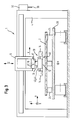
- FIG. 3 shows a partially sectioned front view of the device shown in Fig. 1.
- the respective workpiece 2 can be fixed on the workpiece table 20, for example via vacuum cups 24. It is also possible to integrate corresponding suction or suction openings in the workpiece table or a workpiece band.
- the device 1 comprises a detection device 40 for detecting the relative position of the ink-jet printing device 10 and the respective surface of a workpiece 2 to be patterned.
- the detection device 40 in the present embodiment has several types of sensors 42, 46 which are arranged in the Figures 3, 4 and 5 are best seen.
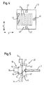
- the detection means 40 in the present Embodiment three distance sensors 42, which are arranged on the printing device 10 adjacent to the nozzles 12 and measure in a direction which is substantially parallel to the ink ejection direction of the nozzles 12 (Fig. 4).
- the absolute distance between the pressure device 10 and the workpiece 2 can be determined with these distance sensors, but beyond that, it is also possible to deduce the exact contour of the respective workpiece 2 from the distance data obtained.
- further distance sensors 42 are each arranged on the printing device 10 via an element 44 pivotable in the present embodiment.
- the pivotable element 44 of the respective sensor can be brought into an extended position, which is best seen in Fig. 5.
- the sensors 42 shown in FIG. 5 measure in a direction that is substantially orthogonal to the ink ejection direction of the nozzles 12. As a result, the thickness or height of the respective area to be printed can be detected and an "overspray" avoided.
- an image sensing sensor 46 is arranged, which also measures in a direction substantially parallel to the ink ejection direction of the nozzles 12.
- the image-capturing sensor 46 can be, for example, a CCD camera or the like, which can produce a complete image of a region of the respective workpiece 2 to be printed or already printed.
- the printing device and preferably also the other operating components of the device 1 are connected to a control device which evaluates the respective data detected by the sensors and on this Basis controls the operation of the device, in particular the printing device.
- the operation of the device can be represented as follows.
- a workpiece 2 is roughly positioned over the stopper pins 22 on the workpiece table 20 and fixed via the vacuum cups 24. Subsequently, the positioning and / or contour of the workpiece 2 are detected on the workpiece table 20 by the sensors 52 and passed this data to the control device.
- the workpiece table 20 is then moved in the x-direction, so that the workpiece 2 can be processed or finished by tools, units or printing units that are inserted into the spindle units 6.
- the operation of the printing device takes place, for example, as follows.
- the printing device 10 On the basis of the data from the sensors 52, the printing device 10 is moved with the corresponding spindle 6 along the portal 4 to the workpiece 2 to be printed.
- the sensors 42, 46 continuously perform a measuring operation, so that the presence and optionally the distance of the respective workpiece and beyond (by the image detection sensor 46) also further information about the workpiece 2 can be obtained.
- the controller Based on these data, the controller outputs pressure signals to the respective nozzles 12 (or the associated piezoelectric actuators or thermocouples) so that the workpiece 2 is printed.
- individual nozzles or nozzle groups can be switched on or off in order to compensate for dimensional, position or other tolerances or deviations of the workpiece 2.
- the sensors 12 are used, which are extendable via pivotable elements 44 in order to detect the height of the narrow surface and thus to prevent overspray.
- drying units 14 After printing on a surface section, it may optionally be dried by the drying units 14, possibly also simultaneously with the printing process.
- FIG. 6 The travel paths of the printing device 10 and / or of the workpiece 2 are shown schematically in FIG.
- the left-hand drawing in FIG. 6 shows an operation in the so-called transverse pressure, in which the printing device 10 moves back and forth along the portal 4 in the y-direction together with the spindle unit 6 and the workpiece 2 through the workpiece table 20 in the x-direction continues to be clocked.
- the printing scheme shown on the right in FIG. 6, which can be referred to as longitudinal printing.
- the printing device 10 is substantially stationary during the printing process itself, and the workpiece 2 is reciprocated with the workpiece table 20 in the x-direction.
- the printing device 10 thus only needs to be clocked in the y-direction after the printing of a web has been completed.
- combinations of both operations are possible, and it can be printed, for example, obliquely arranged tracks or the like.
Landscapes
- Ink Jet (AREA)
Priority Applications (4)
| Application Number | Priority Date | Filing Date | Title |
|---|---|---|---|
| EP06017766.4A EP1837189B1 (fr) | 2006-03-08 | 2006-08-25 | Dispositif pour affiner des pièces à fabriquer |
| PL08021281T PL2065206T3 (pl) | 2006-03-08 | 2006-08-25 | Urządzenie do uszlachetniania detali |
| EP08021281A EP2065206B1 (fr) | 2006-03-08 | 2006-08-25 | Dispositif d'enrichissement de pièces usinées |
| EP06023120A EP1832429A3 (fr) | 2006-03-08 | 2006-11-07 | Dispositif pour décorer des pièces à fabriquer |
Applications Claiming Priority (3)
| Application Number | Priority Date | Filing Date | Title |
|---|---|---|---|
| EP06004713.1A EP1839883B1 (fr) | 2006-03-08 | 2006-03-08 | Procédé et dispositif pour imprimer sur des objets en forme de plaque |
| EP06012041A EP1867488B1 (fr) | 2006-06-12 | 2006-06-12 | Procédé pour décorer la surface de pièces |
| EP06017766.4A EP1837189B1 (fr) | 2006-03-08 | 2006-08-25 | Dispositif pour affiner des pièces à fabriquer |
Related Child Applications (2)
| Application Number | Title | Priority Date | Filing Date |
|---|---|---|---|
| EP08021281A Division EP2065206B1 (fr) | 2006-03-08 | 2006-08-25 | Dispositif d'enrichissement de pièces usinées |
| EP08021281A Division-Into EP2065206B1 (fr) | 2006-03-08 | 2006-08-25 | Dispositif d'enrichissement de pièces usinées |
Publications (3)
| Publication Number | Publication Date |
|---|---|
| EP1837189A2 true EP1837189A2 (fr) | 2007-09-26 |
| EP1837189A3 EP1837189A3 (fr) | 2008-10-15 |
| EP1837189B1 EP1837189B1 (fr) | 2016-10-12 |
Family
ID=38069031
Family Applications (2)
| Application Number | Title | Priority Date | Filing Date |
|---|---|---|---|
| EP06017766.4A Not-in-force EP1837189B1 (fr) | 2006-03-08 | 2006-08-25 | Dispositif pour affiner des pièces à fabriquer |
| EP08021281A Not-in-force EP2065206B1 (fr) | 2006-03-08 | 2006-08-25 | Dispositif d'enrichissement de pièces usinées |
Family Applications After (1)
| Application Number | Title | Priority Date | Filing Date |
|---|---|---|---|
| EP08021281A Not-in-force EP2065206B1 (fr) | 2006-03-08 | 2006-08-25 | Dispositif d'enrichissement de pièces usinées |
Country Status (2)
| Country | Link |
|---|---|
| EP (2) | EP1837189B1 (fr) |
| PL (1) | PL2065206T3 (fr) |
Cited By (14)
| Publication number | Priority date | Publication date | Assignee | Title |
|---|---|---|---|---|
| WO2010031500A1 (fr) * | 2008-09-22 | 2010-03-25 | Baumer Innotec Ag | Réparation automatique d'objets texturés plats tels que des panneaux en bois, au moyen d'une reconstruction esthétique |
| EP2226201A1 (fr) * | 2009-03-04 | 2010-09-08 | Flooring Technologies Ltd. | Procédé et installation destinés à la fabrication d'une plaque de fibre de bois |
| WO2010124307A1 (fr) * | 2009-04-30 | 2010-11-04 | Fill Gesellschaft M.B.H. | Dispositif pour détecter et corriger des points défectueux dans le bois |
| AT508166B1 (de) * | 2009-05-13 | 2012-01-15 | Erwin Ganner Ges M B H U Co Kg | Computergesteuerte bohrmaschine |
| CN103085500A (zh) * | 2011-10-28 | 2013-05-08 | 精工爱普生株式会社 | 被印染材料的支承装置、印染装置以及印染物的制造方法 |
| CN104084804A (zh) * | 2014-06-27 | 2014-10-08 | 赵秋燕 | 一种组合机床 |
| DE102009003443B4 (de) * | 2009-02-05 | 2015-04-16 | Theodor Hymmen Verwaltungs Gmbh | Verfahren und Vorrichtung zum streifenförmigen Bedrucken großformatiger Werkstücke |
| EP3488984A1 (fr) * | 2017-11-24 | 2019-05-29 | SCM Group S.p.A. | Machine pour l'usinage de pièces faites de bois ou equivalent et equipees d'un systeme de detection de presence d'un operateur, et methode d'utilisation |
| CN110143061A (zh) * | 2019-07-02 | 2019-08-20 | 马鞍山纽泽科技服务有限公司 | 一种铁皮专用压印装置 |
| CN111421968A (zh) * | 2019-01-10 | 2020-07-17 | 松下知识产权经营株式会社 | 搬运台以及使用该搬运台的喷墨装置 |
| IT201900021651A1 (it) * | 2019-11-19 | 2021-05-19 | Carlo Rovatti | Dispositivo robotico per la decorazione di elementi di rivestimento per pavimenti, pareti e/o soffitti e relativo sistema e procedimento |
| WO2021110951A1 (fr) | 2019-12-06 | 2021-06-10 | Homag Gmbh | Procédé et machine d'impression sur une pièce |
| CN114393557A (zh) * | 2021-12-30 | 2022-04-26 | 宜兴市华天自动化设备有限公司 | 一种五金产品加工用多功能质检台 |
| WO2023073096A1 (fr) | 2021-10-29 | 2023-05-04 | Homag Gmbh | Dispositif d'impression pour l'impression d'une pièce et procédé |
Families Citing this family (3)
| Publication number | Priority date | Publication date | Assignee | Title |
|---|---|---|---|---|
| DE102012006370A1 (de) | 2012-03-29 | 2013-10-02 | Heidelberger Druckmaschinen Aktiengesellschaft | System zum Bedrucken eines Objekts |
| PT3741573T (pt) | 2019-05-22 | 2024-04-12 | Barberan Latorre Jesus Francisco | Máquina para substratos de impressão e método para substratos de impressão utilizando a referida máquina |
| DE102023110002A1 (de) * | 2023-04-20 | 2024-10-24 | Homag Gmbh | Ausrichteinrichtung zum Ausrichten eines Werkstücks, Druckeinrichtung sowie Verfahren zum Ausrichten eines Werkstücks |
Citations (5)
| Publication number | Priority date | Publication date | Assignee | Title |
|---|---|---|---|---|
| EP0993903A2 (fr) | 1998-10-14 | 2000-04-19 | Fattori S.R.L. | Dispositif pour travailler des pièces en bois |
| DE10031030A1 (de) | 2000-06-26 | 2002-01-17 | Joerg R Bauer | Verfahren und Vorrichtung zum Herstellen flächiger Bauteile mit vorbestimmtem Oberflächenaussehen, insbesondere von Frontplatten von Küchenelementen |
| US20030218663A1 (en) | 2002-04-03 | 2003-11-27 | Baxter William R.S. | Method and apparatus for creating an image on an article and printed article |
| DE202004000662U1 (de) | 2004-01-17 | 2004-04-08 | Homag Holzbearbeitungssysteme Ag | Maschine zum Bedrucken der Schmalseiten plattenförmiger Werkstücke |
| EP1479524A1 (fr) | 2003-05-23 | 2004-11-24 | Jörg R. Bauer | Procède et dispositif permettant de réaliser un élément structurel ayant une apparence de surface predeterminee |
-
2006
- 2006-08-25 EP EP06017766.4A patent/EP1837189B1/fr not_active Not-in-force
- 2006-08-25 EP EP08021281A patent/EP2065206B1/fr not_active Not-in-force
- 2006-08-25 PL PL08021281T patent/PL2065206T3/pl unknown
Patent Citations (5)
| Publication number | Priority date | Publication date | Assignee | Title |
|---|---|---|---|---|
| EP0993903A2 (fr) | 1998-10-14 | 2000-04-19 | Fattori S.R.L. | Dispositif pour travailler des pièces en bois |
| DE10031030A1 (de) | 2000-06-26 | 2002-01-17 | Joerg R Bauer | Verfahren und Vorrichtung zum Herstellen flächiger Bauteile mit vorbestimmtem Oberflächenaussehen, insbesondere von Frontplatten von Küchenelementen |
| US20030218663A1 (en) | 2002-04-03 | 2003-11-27 | Baxter William R.S. | Method and apparatus for creating an image on an article and printed article |
| EP1479524A1 (fr) | 2003-05-23 | 2004-11-24 | Jörg R. Bauer | Procède et dispositif permettant de réaliser un élément structurel ayant une apparence de surface predeterminee |
| DE202004000662U1 (de) | 2004-01-17 | 2004-04-08 | Homag Holzbearbeitungssysteme Ag | Maschine zum Bedrucken der Schmalseiten plattenförmiger Werkstücke |
Cited By (21)
| Publication number | Priority date | Publication date | Assignee | Title |
|---|---|---|---|---|
| US20110194735A1 (en) * | 2008-09-22 | 2011-08-11 | Baumer Innotec Ag | Automatic repair of flat, textured objects, such as wood panels having aesthetic reconstruction |
| WO2010031500A1 (fr) * | 2008-09-22 | 2010-03-25 | Baumer Innotec Ag | Réparation automatique d'objets texturés plats tels que des panneaux en bois, au moyen d'une reconstruction esthétique |
| DE102009003443B4 (de) * | 2009-02-05 | 2015-04-16 | Theodor Hymmen Verwaltungs Gmbh | Verfahren und Vorrichtung zum streifenförmigen Bedrucken großformatiger Werkstücke |
| EP2226201A1 (fr) * | 2009-03-04 | 2010-09-08 | Flooring Technologies Ltd. | Procédé et installation destinés à la fabrication d'une plaque de fibre de bois |
| US8394302B2 (en) | 2009-03-04 | 2013-03-12 | Flooring Technologies Ltd. | Method and installation for producing a wood-fiber board |
| US8790557B2 (en) | 2009-03-04 | 2014-07-29 | Flooring Technologies Ltd. | Method and installation for producing a wood-fiber board |
| WO2010124307A1 (fr) * | 2009-04-30 | 2010-11-04 | Fill Gesellschaft M.B.H. | Dispositif pour détecter et corriger des points défectueux dans le bois |
| EP2522475A1 (fr) * | 2009-04-30 | 2012-11-14 | Fill Gesellschaft m.b.H. | Dispositif pour détecter et corriger des points défectueux dans le bois |
| AT13311U3 (de) * | 2009-04-30 | 2014-03-15 | Fill Gmbh | Vorrichtung zum Erkennen und Korrigieren von Fehlstellen in Holz |
| AT508166B1 (de) * | 2009-05-13 | 2012-01-15 | Erwin Ganner Ges M B H U Co Kg | Computergesteuerte bohrmaschine |
| CN103085500B (zh) * | 2011-10-28 | 2016-02-24 | 精工爱普生株式会社 | 被印染材料的支承装置、印染装置以及印染物的制造方法 |
| CN103085500A (zh) * | 2011-10-28 | 2013-05-08 | 精工爱普生株式会社 | 被印染材料的支承装置、印染装置以及印染物的制造方法 |
| CN104084804A (zh) * | 2014-06-27 | 2014-10-08 | 赵秋燕 | 一种组合机床 |
| EP3488984A1 (fr) * | 2017-11-24 | 2019-05-29 | SCM Group S.p.A. | Machine pour l'usinage de pièces faites de bois ou equivalent et equipees d'un systeme de detection de presence d'un operateur, et methode d'utilisation |
| CN111421968A (zh) * | 2019-01-10 | 2020-07-17 | 松下知识产权经营株式会社 | 搬运台以及使用该搬运台的喷墨装置 |
| CN110143061A (zh) * | 2019-07-02 | 2019-08-20 | 马鞍山纽泽科技服务有限公司 | 一种铁皮专用压印装置 |
| IT201900021651A1 (it) * | 2019-11-19 | 2021-05-19 | Carlo Rovatti | Dispositivo robotico per la decorazione di elementi di rivestimento per pavimenti, pareti e/o soffitti e relativo sistema e procedimento |
| WO2021110951A1 (fr) | 2019-12-06 | 2021-06-10 | Homag Gmbh | Procédé et machine d'impression sur une pièce |
| WO2023073096A1 (fr) | 2021-10-29 | 2023-05-04 | Homag Gmbh | Dispositif d'impression pour l'impression d'une pièce et procédé |
| DE102021128270A1 (de) | 2021-10-29 | 2023-05-04 | Homag Gmbh | Druckvorrichtung zum Bedrucken eines Werkstücks sowie Verfahren |
| CN114393557A (zh) * | 2021-12-30 | 2022-04-26 | 宜兴市华天自动化设备有限公司 | 一种五金产品加工用多功能质检台 |
Also Published As
| Publication number | Publication date |
|---|---|
| EP2065206A1 (fr) | 2009-06-03 |
| EP1837189A3 (fr) | 2008-10-15 |
| EP1837189B1 (fr) | 2016-10-12 |
| PL2065206T3 (pl) | 2011-05-31 |
| EP2065206B1 (fr) | 2010-12-29 |
Similar Documents
| Publication | Publication Date | Title |
|---|---|---|
| EP1892107B1 (fr) | Dipositif pour imprimer un motif sur des pièces d'usinage | |
| EP2065206B1 (fr) | Dispositif d'enrichissement de pièces usinées | |
| EP1726443B1 (fr) | Procédé et appareil pour marquer les côtés d'une pièce detacheée plane | |
| DE2640256C2 (fr) | ||
| DE102008032160B4 (de) | Verfahren zum Aufteilen plattenförmiger Werkstücke, sowie Plattenaufteilanlage | |
| US20090120249A1 (en) | Device For Refining Workpieces | |
| EP2832546A1 (fr) | Imprimante dotée d'une commande de tête d'impression | |
| EP2536567A1 (fr) | Dispositif et procédé pour imprimer une image polychrome sur des surfaces de panneaux de matériau, notamment des panneaux de bois | |
| AT500768A1 (de) | Bearbeitungseinrichtung | |
| EP2718108B1 (fr) | Methode d'impression d'objets et machine d'impression | |
| EP2452817B1 (fr) | Dispositif de transfert de feuilles doté d'un système de guidage variable | |
| EP3493948B1 (fr) | Dispositif de ponçage et procede de fonctionnement du dispositif de ponçage | |
| EP1088661B1 (fr) | Procédé et dispositif de décoration d'objets individuels | |
| DE102009003443B4 (de) | Verfahren und Vorrichtung zum streifenförmigen Bedrucken großformatiger Werkstücke | |
| DE102014225206B4 (de) | Rollen-Druckmaschine | |
| EP4272969B1 (fr) | Dispositif de finition d'une surface de pièce à tête d'impression pivotante | |
| EP3184313B1 (fr) | Dispositif et procede destines a l'impression de produits imprimes | |
| EP1832429A2 (fr) | Dispositif pour décorer des pièces à fabriquer | |
| DE102014225204B4 (de) | Druckaggregat | |
| EP4197799A1 (fr) | Dispositif d'impression et procédé d'impression d'une pièce à usiner | |
| DE69731554T2 (de) | Bilderzeugungsgerät des scannertyps | |
| DE10023513C2 (de) | Vorrichtung zur off-line Qualitätsdatenerfassung von Druckprodukten | |
| DE102014225202B4 (de) | Druckaggregat | |
| DE202019001174U1 (de) | Automatische, dynamische Konturanpassung für den Digitaldruck, insbesondere Inkjet Druck, auf mehrdimensionale Oberflächen bzw. Geometrien | |
| DE3914973C1 (fr) |
Legal Events
| Date | Code | Title | Description |
|---|---|---|---|
| PUAI | Public reference made under article 153(3) epc to a published international application that has entered the european phase |
Free format text: ORIGINAL CODE: 0009012 |
|
| AK | Designated contracting states |
Kind code of ref document: A2 Designated state(s): AT BE BG CH CY CZ DE DK EE ES FI FR GB GR HU IE IS IT LI LT LU LV MC NL PL PT RO SE SI SK TR |
|
| AX | Request for extension of the european patent |
Extension state: AL BA HR MK YU |
|
| RIC1 | Information provided on ipc code assigned before grant |
Ipc: B41J 3/28 20060101ALI20080428BHEP Ipc: B41J 3/44 20060101ALI20080428BHEP Ipc: B23Q 1/01 20060101ALI20080428BHEP Ipc: B44C 5/04 20060101ALI20080428BHEP Ipc: B41J 3/407 20060101AFI20070608BHEP Ipc: B27M 1/08 20060101ALI20080428BHEP Ipc: B23Q 1/70 20060101ALI20080428BHEP |
|
| PUAL | Search report despatched |
Free format text: ORIGINAL CODE: 0009013 |
|
| AK | Designated contracting states |
Kind code of ref document: A3 Designated state(s): AT BE BG CH CY CZ DE DK EE ES FI FR GB GR HU IE IS IT LI LT LU LV MC NL PL PT RO SE SI SK TR |
|
| AX | Request for extension of the european patent |
Extension state: AL BA HR MK RS |
|
| 17P | Request for examination filed |
Effective date: 20090331 |
|
| AKX | Designation fees paid |
Designated state(s): DE ES FR IT PL |
|
| 17Q | First examination report despatched |
Effective date: 20091023 |
|
| APBK | Appeal reference recorded |
Free format text: ORIGINAL CODE: EPIDOSNREFNE |
|
| APBN | Date of receipt of notice of appeal recorded |
Free format text: ORIGINAL CODE: EPIDOSNNOA2E |
|
| APBR | Date of receipt of statement of grounds of appeal recorded |
Free format text: ORIGINAL CODE: EPIDOSNNOA3E |
|
| APAF | Appeal reference modified |
Free format text: ORIGINAL CODE: EPIDOSCREFNE |
|
| APBT | Appeal procedure closed |
Free format text: ORIGINAL CODE: EPIDOSNNOA9E |
|
| GRAC | Information related to communication of intention to grant a patent modified |
Free format text: ORIGINAL CODE: EPIDOSCIGR1 |
|
| GRAP | Despatch of communication of intention to grant a patent |
Free format text: ORIGINAL CODE: EPIDOSNIGR1 |
|
| INTG | Intention to grant announced |
Effective date: 20160430 |
|
| INTG | Intention to grant announced |
Effective date: 20160502 |
|
| GRAS | Grant fee paid |
Free format text: ORIGINAL CODE: EPIDOSNIGR3 |
|
| GRAA | (expected) grant |
Free format text: ORIGINAL CODE: 0009210 |
|
| AK | Designated contracting states |
Kind code of ref document: B1 Designated state(s): DE ES FR IT PL |
|
| RAP1 | Party data changed (applicant data changed or rights of an application transferred) |
Owner name: HOMAG GMBH |
|
| REG | Reference to a national code |
Ref country code: DE Ref legal event code: R096 Ref document number: 502006015199 Country of ref document: DE |
|
| REG | Reference to a national code |
Ref country code: DE Ref legal event code: R097 Ref document number: 502006015199 Country of ref document: DE |
|
| PLBE | No opposition filed within time limit |
Free format text: ORIGINAL CODE: 0009261 |
|
| STAA | Information on the status of an ep patent application or granted ep patent |
Free format text: STATUS: NO OPPOSITION FILED WITHIN TIME LIMIT |
|
| 26N | No opposition filed |
Effective date: 20170713 |
|
| REG | Reference to a national code |
Ref country code: FR Ref legal event code: ST Effective date: 20180430 |
|
| PG25 | Lapsed in a contracting state [announced via postgrant information from national office to epo] |
Ref country code: FR Free format text: LAPSE BECAUSE OF NON-PAYMENT OF DUE FEES Effective date: 20170831 |
|
| PGFP | Annual fee paid to national office [announced via postgrant information from national office to epo] |
Ref country code: ES Payment date: 20190902 Year of fee payment: 14 |
|
| PGFP | Annual fee paid to national office [announced via postgrant information from national office to epo] |
Ref country code: PL Payment date: 20190802 Year of fee payment: 14 |
|
| REG | Reference to a national code |
Ref country code: ES Ref legal event code: FD2A Effective date: 20220110 |
|
| PG25 | Lapsed in a contracting state [announced via postgrant information from national office to epo] |
Ref country code: ES Free format text: LAPSE BECAUSE OF NON-PAYMENT OF DUE FEES Effective date: 20200826 |
|
| PGFP | Annual fee paid to national office [announced via postgrant information from national office to epo] |
Ref country code: IT Payment date: 20220818 Year of fee payment: 17 |
|
| PG25 | Lapsed in a contracting state [announced via postgrant information from national office to epo] |
Ref country code: PL Free format text: LAPSE BECAUSE OF NON-PAYMENT OF DUE FEES Effective date: 20200825 |
|
| P01 | Opt-out of the competence of the unified patent court (upc) registered |
Effective date: 20230529 |
|
| PGFP | Annual fee paid to national office [announced via postgrant information from national office to epo] |
Ref country code: DE Payment date: 20230816 Year of fee payment: 18 |
|
| PG25 | Lapsed in a contracting state [announced via postgrant information from national office to epo] |
Ref country code: IT Free format text: LAPSE BECAUSE OF NON-PAYMENT OF DUE FEES Effective date: 20230825 |
|
| REG | Reference to a national code |
Ref country code: DE Ref legal event code: R119 Ref document number: 502006015199 Country of ref document: DE |
|
| PG25 | Lapsed in a contracting state [announced via postgrant information from national office to epo] |
Ref country code: DE Free format text: LAPSE BECAUSE OF NON-PAYMENT OF DUE FEES Effective date: 20250301 |