EP1837221B1 - Toit escamotable pour un véhicule automobile - Google Patents
Toit escamotable pour un véhicule automobile Download PDFInfo
- Publication number
- EP1837221B1 EP1837221B1 EP07004716.2A EP07004716A EP1837221B1 EP 1837221 B1 EP1837221 B1 EP 1837221B1 EP 07004716 A EP07004716 A EP 07004716A EP 1837221 B1 EP1837221 B1 EP 1837221B1
- Authority
- EP
- European Patent Office
- Prior art keywords
- main
- seal carrier
- folding top
- rotation
- hinges
- Prior art date
- Legal status (The legal status is an assumption and is not a legal conclusion. Google has not performed a legal analysis and makes no representation as to the accuracy of the status listed.)
- Not-in-force
Links
- 230000007246 mechanism Effects 0.000 description 6
- 230000002349 favourable effect Effects 0.000 description 4
- 239000000463 material Substances 0.000 description 4
- 230000004308 accommodation Effects 0.000 description 3
- 230000008878 coupling Effects 0.000 description 3
- 238000010168 coupling process Methods 0.000 description 3
- 238000005859 coupling reaction Methods 0.000 description 3
- 239000000969 carrier Substances 0.000 description 2
- 238000010276 construction Methods 0.000 description 2
- 239000002184 metal Substances 0.000 description 2
- 230000005540 biological transmission Effects 0.000 description 1
- 230000001419 dependent effect Effects 0.000 description 1
- 238000005516 engineering process Methods 0.000 description 1
- 239000004744 fabric Substances 0.000 description 1
- 238000004519 manufacturing process Methods 0.000 description 1
- 238000007789 sealing Methods 0.000 description 1
Images


Classifications
-
- B—PERFORMING OPERATIONS; TRANSPORTING
- B60—VEHICLES IN GENERAL
- B60J—WINDOWS, WINDSCREENS, NON-FIXED ROOFS, DOORS, OR SIMILAR DEVICES FOR VEHICLES; REMOVABLE EXTERNAL PROTECTIVE COVERINGS SPECIALLY ADAPTED FOR VEHICLES
- B60J7/00—Non-fixed roofs; Roofs with movable panels, e.g. rotary sunroofs
- B60J7/08—Non-fixed roofs; Roofs with movable panels, e.g. rotary sunroofs of non-sliding type, i.e. movable or removable roofs or panels, e.g. let-down tops or roofs capable of being easily detached or of assuming a collapsed or inoperative position
- B60J7/12—Non-fixed roofs; Roofs with movable panels, e.g. rotary sunroofs of non-sliding type, i.e. movable or removable roofs or panels, e.g. let-down tops or roofs capable of being easily detached or of assuming a collapsed or inoperative position foldable; Tensioning mechanisms therefor, e.g. struts
- B60J7/1226—Soft tops for convertible vehicles
- B60J7/1265—Soft tops for convertible vehicles characterised by kinematic movements, e.g. using parallelogram linkages
Definitions
- the present invention relates to a folding top for a motor vehicle, with a main column and a main handlebar having top linkage, wherein the main column and the main link are each mounted via a first pivot point to a body-fixed main bearing of the vehicle and via a respective second hinge point by means of a roof frame member articulated with each other and a seal carrier pivotally connected to the main pillar or main link so as to allow relative movement relative to the main pillar and the main link.
- Faltverpart An important task in the construction of Faltverpart is the space-saving accommodation of the discarded top. In particular, it is endeavored to pivot the attached to the hood frame seal carrier when placing the top in a space-saving position.
- the present invention is concerned with the arranged on the C-pillar of the folding top seal, which provides a sealing function to the rear side window of the vehicle in the closed state of the hood.
- the seal carrier is pivotally connected to the main column, and it is further articulated via a hingedly attached to the body-fixed main bearing coupling rod.
- This has the consequence that when pivoting the main column to the rear over the coupling rod, a force is exerted on the seal carrier, the latter in the stowed state of the hood in a space-saving position brings.
- the seal performs only a rotational movement about the longitudinal edge of the roof part on which it is mounted.
- the invention is therefore based on the object to improve the described systems of the prior art such that the folding top provides a movement mechanism for a seal carrier that allows flexible movements as possible and is easy to implement.
- the folding top for a motor vehicle builds on the generic state of the art in that the seal carrier is further connected in an articulated manner to the roof frame element.
- This structure is the basis for realizing a folding top, which is less sensitive to tolerances, because the introduction of force via the roof frame element allows a structure with larger lever paths than known movement mechanisms for the seal carrier.
- this design has the great advantage that it can be dispensed with 3D joints or ball joints that significantly increase the cost of the structure.
- this folding top is production and assembly technology favorable. Due to the flexible design possibility of the dimension ratio, 3D layers with a wide area can be created in this design Realize scope. In addition, this structure can be designed so that it leads to a very favorable force application. By means of the dimensional ratios of the individual articulated coupling components, adjustments can also be made with respect to the vehicle body shell.
- the folding top according to the invention can be advantageously further developed in that the seal carrier is coupled by means of a seal carrier linkage via two joints with the roof frame element, and is coupled by means of another seal carrier linkage via two further joints with the main column or the main link.
- the joints are swivel joints, which in each case only allow a two-dimensionally articulated connection.
- the folding top according to the invention can be developed such that an axis of rotation of at least two joints is in each case substantially in the same plane, such as a curve which is described by a point of the associated axis of rotation of the joints when pivoting a four-joint formed from the main column and main link ,
- the folding top according to the invention can be developed such that a rotation axis of three joints is in each case substantially in the same plane, such as a curve which is described by a point of the associated axis of rotation of the joints when pivoting a four-joint formed from the main column and main link.
- This structure leads to a particularly favorable introduction of force.
- the folding top according to the invention can be developed such that the two joints closest to the main bearing have substantially parallel axes of rotation. This design also leads to an improved introduction of force and thus to avoid excessive material stress of the top linkage.
- the folding top according to the invention can be designed so that the joint, which connects one of the seal carrier arm to the roof frame member (44), has an axis of rotation which is substantially perpendicular to the substantially parallel axes of rotation. Due to these geometric relationships, 3D movements can be realized while avoiding ball joints with a favorable force introduction.
- the folding top according to the invention builds on the generic state of the art in that the further away from the main bearing joint of the joints, which connect the seal carrier with the seal carrier links, has a rotation axis, which spans to the substantially parallel axes of rotation a maximum of 55 °. Up to an angle of maximum 55 °, the structure can be realized without the use of ball joints, without excessively high forces acting on the top linkage.
- the folding top according to the invention can be developed such that at least the axes of rotation of the two joints closest to the main bearing are substantially perpendicular to the main column or to the main link.
- Such a construction makes it possible to design the movement mechanism for the seal carrier in such a way that it is guided in front of or behind the main column or the main link relative to the vehicle longitudinal axis and thus leads to a space-saving arrangement in the folded state of the folding hood in the vertical direction.
- the folding top according to the invention can be designed so that allows a pivotal movement of the seal carrier in a transverse direction of the folding top of the joints of the further away from the main bearing seal carrier handlebar.
- the seal carrier can be moved sideways, so that it comes to rest in the stored state in a plane with other seal carriers of the folding top and thus provides a particularly space-saving, folded folding top.
- the invention further relates to a motor vehicle with a folding top according to the invention, wherein the motor vehicle offers the advantages described above in a transferred manner.
- FIG. 1 shows a side view of a motor vehicle with the folding top according to the invention in the closed state.
- the folding top 10 of a motor vehicle 12 has a top linkage 14 and a top cloth 16 held and supported by the top linkage 14.
- the top linkage 14 is constructed symmetrically to a vertical vehicle longitudinal center plane.
- the directional indication "longitudinal direction of the folding top” used in the following corresponds to the right-left direction in FIG. 1
- the direction “transverse direction of the folding top” corresponds to the viewing direction of FIG. 1 ,
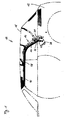
- FIG. 2 shows a perspective view of a folding top according to the invention in the closed state.
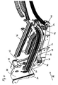
- This folding top is in the Figures 3 and 4 shown in detail, in which FIG. 3 a section I and FIG. 4 a section II FIG. 2 represents.
- the folding top 10 comprises, in the direction of travel from front to back, a front bow 18, a roof cassette 20, a main bow 22 and a corner bow 24.
- a rear window 26 and a clamping bracket 28 are further arranged.
- the bow 18, 22, 24 and the roof cassette 20 form transversely to the direction of travel extending elements of the top linkage 14, which are laterally connected to side parts of the top linkage 14.
- the rear side elements of the top linkage 14 are of particular interest.
- a main pillar 30 and a main link 32 which are articulated via pivot points 34, 36 to a main body bearing 38 fixed to the body.
- the main pillar 30 and the main link 32 via hinge points 40, 42 are connected by means of a roof frame member 44 hinged together and thus form a four-bar linkage.
- the hinge points 34, 36, 40 and 42 are preferably formed by means of swivel joints.
- the main link 32 the other middle and front lateral elements of the roof linkage 14 close.
- a front seal carrier 46 and a middle seal carrier 48 are attached.
- a rear seal carrier 50 forms a movement mechanism for the seal carrier 50.
- the seal supports 46-50 each carry a seal which preferably consists of a rubber material to seal the side windows of the motor vehicle 12 with the side windows closed and the folding top 10 closed.
- the seals are in each case attached to the seal carriers 46 - 50 or formed integrally therewith.
- the seal carrier 50 is at an upper portion as in FIG. 3 represented by means of a seal carrier arm 52 via the roof frame element 44 coupled to the main column 30 and the main link 32.
- the seal carrier link 52 is a connector, which is preferably made of metal.
- the seal carrier arm 52 has at one end portion a pivot joint 54, whereby the seal support arm 52 is pivotally connected to the roof frame member 44.
- a hinge 56 is provided to connect the rear seal carrier 50 with the seal carrier arm 52 articulated.
- the respective axes of rotation 58 and 60 of the hinges 54 and 56 are preferably perpendicular to each other.
- the pivot 56 is attached to the rear seal carrier 50 by means of a tongue-shaped protruding from the seal carrier 50 mounting flange 62.
- a tongue-shaped mounting flange 64 extends in the transverse direction of the folding top 10 in the direction of the center of the folding top 10 past the main column 30.
- the end of the mounting flange 64 facing away from the rear seal carrier 50 is provided with a hinge 66 to articulate with a seal carrier handlebar 68 produce.
- This seal carrier arm 68 is a flat elongated connector, which preferably consists of metal and is pivotally connected at one end to the mounting flange 64.
- At the other end portion of the seal carrier arm 68 is pivotally connected via a rotary joint 70 with the main column 30. More specifically, the pivot 70 engages the main pillar 30 at a tongue-shaped mounting flange 72 which extends in the opposite transverse direction of the folding roof 10 as the mounting flange 64.
- the axes of rotation 74 and 76 of the respective hinges 66 and 70 are preferably parallel and preferably also the axis of rotation 60 of the pivot 56 is parallel to the axes of rotation 74 and 76,
- the present invention is feasible up to a maximum angle of 55 ° between the parallel axes of rotation 74, 76 and the axis of rotation 60, without ball joints are required.
- the joints 54, 56, 66 and 70 are executable as sockets, in each of which a bolt is guided.
- the just-mentioned distance change between axis of rotation 58 and axis of rotation 76 leads to a pivoting movement of the rear seal carrier 50 to the outside, ie away from the main column 30.
- the seal carrier 50 pivots mainly about the axis of rotation 60. A tilting movement of the seal carrier 50 is negligible.
- FIG. 5 shows a perspective view of a folding top 10 according to FIG. 2 in an intermediate position between closed and stored state.
- To deposit the folding top 10 (not shown) drive the main column 30 and the main link 32 is pivoted backwards, due to the four-joint-like arrangement different parallelogram-like intermediate states are taken in succession.
- FIG. 6 shows a perspective view of the folding top according to FIG. 2 in the stowed state.
- FIG. 7 shows the stored state of the folding top FIG. 6 from the in FIG. 6 marked direction III considered.
- the stored state of the folding top 10 of the seal carrier 50 and thus in practice also the seal carried by this at least partially adjacent to the front and rear seal carrier 46 and 48.
- the height of the stored folding top 10 remains low.
- the stroke that brings the seal carrier 50 in its storage position is based on the relative movement between the main column 30 and the main link 32, due to the low power transmission angle comparatively small forces sufficient to bring about the advantageous storage position of the seal carrier 50.
Landscapes
- Engineering & Computer Science (AREA)
- Mechanical Engineering (AREA)
- Seal Device For Vehicle (AREA)
- Superstructure Of Vehicle (AREA)
Claims (11)
- Toit escamotable pliable pour un véhicule automobile, avec une tige escamotable (14) comprenant un montant principal (30) et un bras oscillant principal (32), le montant principal (30) et le bras oscillant principal (32) étant disposés respectivement au niveau d'un palier de roulement principal (38) du véhicule fixé à la carrosserie par le biais d'un premier point d'articulation (34, 36) et étant reliés de façon articulée l'un à l'autre à l'aide d'un élément de cadre de toit (44) par le biais respectivement d'un deuxième point d'articulation (40, 42) et avec un support de joint (50) relié de façon articulée (66, 70) au montant principal (30) ou au bras oscillant principal (32) de façon à permettre un mouvement relatif par rapport au montant principal (30) et au bras oscillant principal (32), caractérisé en ce que le support de joint (50) est en outre relié de façon articulée (54, 56) à l'élément de cadre de toit (44).
- Toit escamotable pliable selon la revendication 1, caractérisé en ce que le support de joint (50) est couplé à l'élément de cadre de toit (44) à l'aide d'un bras oscillant de support de joint (52) par le biais de deux articulations (54, 56) et est couplé au montant principal (30) ou au bras oscillant principal (32) à l'aide d'un bras oscillant de support de joint (68) supplémentaire par le biais de deux articulations (66, 70) supplémentaires.
- Toit escamotable pliable selon la revendication 2, caractérisé en ce que les articulations (54, 56, 66, 70) sont des articulations pivotantes ne permettant respectivement qu'une jonction articulée dans deux dimensions.
- Toit escamotable pliable selon la revendication 3, caractérisé en ce qu'un axe de rotation (74, 76) d'au moins deux articulations (66, 70) se place respectivement pour l'essentiel dans le même plan qu'une courbe décrite lors du pivotement d'une articulation à quatre points formée à partir du montant principal (30) et du bras oscillant principal (32) en partant d'un point de l'axe de rotation (74, 76) associé des articulations (66, 70).
- Toit escamotable pliable selon la revendication 3, caractérisé en ce qu'un axe de rotation (60, 74, 76) de trois articulations (56, 66, 70) se place respectivement pour l'essentiel dans le même plan qu'une courbe décrite lors du pivotement d'une articulation à quatre points formée à partir du montant principal (30) et du bras oscillant principal (32) en partant d'un point de l'axe de rotation (60, 74, 76) associé des articulations (56, 66, 70).
- Toit escamotable pliable selon l'une quelconque des revendications 3 à 5, caractérisé en ce que les deux articulations (66, 70) connexes par rapport au palier de roulement principal (38) comportent pour l'essentiel des axes de rotation parallèles.
- Toit escamotable pliable selon la revendication 6, caractérisé en ce que l'articulation (54) reliant un des bras oscillants de support de joint (52) à l'élément de cadre de toit (44) comporte un axe de rotation (58) pour l'essentiel perpendiculaire aux axes de rotation (74, 76) pour l'essentiel parallèles.
- Toit escamotable pliable selon la revendication 6, caractérisé en ce que l'articulation (56) davantage éloignée du palier de roulement principal (38) parmi les articulations (56, 66) reliant le support de joint (50) aux bras oscillants de support de joint (52, 68) comporte un axe de rotation (60) présentant au maximum un angle de 55° par rapport aux axes de rotation (74, 76) pour l'essentiel parallèles.
- Toit escamotable pliable selon l'une quelconque des revendications 3 à 8, caractérisé en ce qu'au moins les axes de rotation (74, 76) des deux articulations (66, 70) connexes par rapport au palier de roulement principal (38) sont pour l'essentiel parallèles au montant principal (30) ou au bras oscillant principal (32).
- Toit escamotable pliable selon l'une quelconque des revendications 2 à 9, caractérisé en ce qu'un mouvement de pivotement du support de joint (50) est rendu possible dans une direction transversale du toit escamotable pliable par une (56) des articulations (54, 56) du bras oscillant de support de joint (52) davantage éloigné du palier de roulement principal (38).
- Véhicule automobile doté d'un toit escamotable pliable selon l'une quelconque des revendications précédentes.
Applications Claiming Priority (1)
| Application Number | Priority Date | Filing Date | Title |
|---|---|---|---|
| DE102006012652A DE102006012652B3 (de) | 2006-03-20 | 2006-03-20 | Faltverdeck für ein Kraftfahrzeug |
Publications (3)
| Publication Number | Publication Date |
|---|---|
| EP1837221A2 EP1837221A2 (fr) | 2007-09-26 |
| EP1837221A3 EP1837221A3 (fr) | 2009-01-21 |
| EP1837221B1 true EP1837221B1 (fr) | 2013-09-18 |
Family
ID=38170166
Family Applications (1)
| Application Number | Title | Priority Date | Filing Date |
|---|---|---|---|
| EP07004716.2A Not-in-force EP1837221B1 (fr) | 2006-03-20 | 2007-03-07 | Toit escamotable pour un véhicule automobile |
Country Status (2)
| Country | Link |
|---|---|
| EP (1) | EP1837221B1 (fr) |
| DE (1) | DE102006012652B3 (fr) |
Family Cites Families (5)
| Publication number | Priority date | Publication date | Assignee | Title |
|---|---|---|---|---|
| DE19942427B4 (de) * | 1999-09-06 | 2006-11-09 | Webasto Ag | Faltverdeck für ein Cabriolet |
| DE10051436B4 (de) * | 2000-10-17 | 2004-06-17 | Webasto Vehicle Systems International Gmbh | Dichtungsvorrichtung für ein Dachteil eines Fahrzeugdaches |
| DE10160240B4 (de) * | 2001-12-07 | 2005-04-07 | Webasto Ag | Faltverdeck für ein Kraftfahrzeug |
| DE10317416B4 (de) * | 2003-04-15 | 2006-08-03 | Webasto Ag | Falt- oder Klappverdeck für ein Fahrzeug |
| DE102004005882B4 (de) * | 2004-02-05 | 2006-06-08 | Open Air Systems Gmbh | Verdeck eines Kraftfahrzeugs |
-
2006
- 2006-03-20 DE DE102006012652A patent/DE102006012652B3/de not_active Expired - Fee Related
-
2007
- 2007-03-07 EP EP07004716.2A patent/EP1837221B1/fr not_active Not-in-force
Also Published As
| Publication number | Publication date |
|---|---|
| EP1837221A2 (fr) | 2007-09-26 |
| DE102006012652B3 (de) | 2007-07-12 |
| EP1837221A3 (fr) | 2009-01-21 |
Similar Documents
| Publication | Publication Date | Title |
|---|---|---|
| EP1275543B1 (fr) | Dispositif de couverture pour compartiment de stockage de capote | |
| EP1308333B1 (fr) | Toit escamotable pour véhicule convertible | |
| EP1840011B1 (fr) | Déflecteur aérodynamique pour un véhicule | |
| EP2018288B1 (fr) | Dispositif pour guider le mouvement d'un déflecteur d'air | |
| DE19936252C5 (de) | Hardtop-Fahrzeugdach | |
| EP1226044B1 (fr) | Capote de vehicule pouvant passer d'une position fermee a une position plage arriere | |
| EP1275544B1 (fr) | Dispositif pour la couverture du compartiment de garde d'un toit de véhicule | |
| EP1989074B1 (fr) | Capote dépliante pour un véhicule automobile | |
| DE10258053A1 (de) | Abklappbare Dachabdeckung für Fahrzeuge, insbesondere Pkw | |
| EP1904327B1 (fr) | Dispositif de deplacement d'un couvercle de compartiment a capote d'un cabriolet | |
| EP2020366A2 (fr) | Agencement de spoiler de toit pour cabine du chauffeur d'un véhicule utilitaire | |
| EP1897718B1 (fr) | Capote pliable | |
| EP1735171B1 (fr) | Cinematique de direction pour toit rigide de vehicule cabriolet | |
| EP1837221B1 (fr) | Toit escamotable pour un véhicule automobile | |
| EP1982858B1 (fr) | Toit escamotable pour un véhicule de transport de personnes | |
| WO2007115714A1 (fr) | Capote de toit ouvrant pour un vehicule automobile ouvert | |
| DE19960011C2 (de) | Klappverdeck für Kraftfahrzeuge, insbesondere Personenkraftwagen | |
| DE102011117371A1 (de) | Faltdach-Vorrichtung für ein Fahrzeug | |
| EP1853448B1 (fr) | Dispositif de commande d'un composant pivotant d'un vehicule | |
| DE102007050210A1 (de) | Schwenkeinrichtung für einen Deckel | |
| DE102008036907B4 (de) | Faltverdeck für einen Personenkraftwagen | |
| DE102013103420B4 (de) | Cabriolet-Verdeck mit Antrieb für Verschlussanordnungen | |
| EP1798090B1 (fr) | Plage arrière pour cabriolet | |
| DE102006058320B4 (de) | Cabriolet-Fahrzeug mit angetriebenem Hauptlenkersystem | |
| DE10349042B3 (de) | Mehrgelenkkinematik für ein verstellbares Fahrzeugdach |
Legal Events
| Date | Code | Title | Description |
|---|---|---|---|
| PUAI | Public reference made under article 153(3) epc to a published international application that has entered the european phase |
Free format text: ORIGINAL CODE: 0009012 |
|
| AK | Designated contracting states |
Kind code of ref document: A2 Designated state(s): AT BE BG CH CY CZ DE DK EE ES FI FR GB GR HU IE IS IT LI LT LU LV MC MT NL PL PT RO SE SI SK TR |
|
| AX | Request for extension of the european patent |
Extension state: AL BA HR MK YU |
|
| PUAL | Search report despatched |
Free format text: ORIGINAL CODE: 0009013 |
|
| AK | Designated contracting states |
Kind code of ref document: A3 Designated state(s): AT BE BG CH CY CZ DE DK EE ES FI FR GB GR HU IE IS IT LI LT LU LV MC MT NL PL PT RO SE SI SK TR |
|
| AX | Request for extension of the european patent |
Extension state: AL BA HR MK RS |
|
| 17P | Request for examination filed |
Effective date: 20080328 |
|
| AKX | Designation fees paid |
Designated state(s): AT BE BG CH CY CZ DE DK EE ES FI FR GB GR HU IE IS IT LI LT LU LV MC MT NL PL PT RO SE SI SK TR |
|
| GRAP | Despatch of communication of intention to grant a patent |
Free format text: ORIGINAL CODE: EPIDOSNIGR1 |
|
| INTG | Intention to grant announced |
Effective date: 20130507 |
|
| GRAS | Grant fee paid |
Free format text: ORIGINAL CODE: EPIDOSNIGR3 |
|
| GRAA | (expected) grant |
Free format text: ORIGINAL CODE: 0009210 |
|
| AK | Designated contracting states |
Kind code of ref document: B1 Designated state(s): AT BE BG CH CY CZ DE DK EE ES FI FR GB GR HU IE IS IT LI LT LU LV MC MT NL PL PT RO SE SI SK TR |
|
| REG | Reference to a national code |
Ref country code: GB Ref legal event code: FG4D Free format text: NOT ENGLISH |
|
| REG | Reference to a national code |
Ref country code: CH Ref legal event code: EP |
|
| REG | Reference to a national code |
Ref country code: IE Ref legal event code: FG4D Free format text: LANGUAGE OF EP DOCUMENT: GERMAN |
|
| REG | Reference to a national code |
Ref country code: AT Ref legal event code: REF Ref document number: 632543 Country of ref document: AT Kind code of ref document: T Effective date: 20131015 |
|
| REG | Reference to a national code |
Ref country code: DE Ref legal event code: R096 Ref document number: 502007012291 Country of ref document: DE Effective date: 20131114 |
|
| RAP2 | Party data changed (patent owner data changed or rights of a patent transferred) |
Owner name: WEBASTO SE |
|
| PG25 | Lapsed in a contracting state [announced via postgrant information from national office to epo] |
Ref country code: CY Free format text: LAPSE BECAUSE OF FAILURE TO SUBMIT A TRANSLATION OF THE DESCRIPTION OR TO PAY THE FEE WITHIN THE PRESCRIBED TIME-LIMIT Effective date: 20130724 Ref country code: SE Free format text: LAPSE BECAUSE OF FAILURE TO SUBMIT A TRANSLATION OF THE DESCRIPTION OR TO PAY THE FEE WITHIN THE PRESCRIBED TIME-LIMIT Effective date: 20130918 Ref country code: LT Free format text: LAPSE BECAUSE OF FAILURE TO SUBMIT A TRANSLATION OF THE DESCRIPTION OR TO PAY THE FEE WITHIN THE PRESCRIBED TIME-LIMIT Effective date: 20130918 |
|
| REG | Reference to a national code |
Ref country code: NL Ref legal event code: VDEP Effective date: 20130918 |
|
| REG | Reference to a national code |
Ref country code: LT Ref legal event code: MG4D |
|
| PG25 | Lapsed in a contracting state [announced via postgrant information from national office to epo] |
Ref country code: FI Free format text: LAPSE BECAUSE OF FAILURE TO SUBMIT A TRANSLATION OF THE DESCRIPTION OR TO PAY THE FEE WITHIN THE PRESCRIBED TIME-LIMIT Effective date: 20130918 Ref country code: SI Free format text: LAPSE BECAUSE OF FAILURE TO SUBMIT A TRANSLATION OF THE DESCRIPTION OR TO PAY THE FEE WITHIN THE PRESCRIBED TIME-LIMIT Effective date: 20130918 Ref country code: LV Free format text: LAPSE BECAUSE OF FAILURE TO SUBMIT A TRANSLATION OF THE DESCRIPTION OR TO PAY THE FEE WITHIN THE PRESCRIBED TIME-LIMIT Effective date: 20130918 Ref country code: ES Free format text: LAPSE BECAUSE OF FAILURE TO SUBMIT A TRANSLATION OF THE DESCRIPTION OR TO PAY THE FEE WITHIN THE PRESCRIBED TIME-LIMIT Effective date: 20130918 Ref country code: GR Free format text: LAPSE BECAUSE OF FAILURE TO SUBMIT A TRANSLATION OF THE DESCRIPTION OR TO PAY THE FEE WITHIN THE PRESCRIBED TIME-LIMIT Effective date: 20131219 |
|
| PG25 | Lapsed in a contracting state [announced via postgrant information from national office to epo] |
Ref country code: CY Free format text: LAPSE BECAUSE OF FAILURE TO SUBMIT A TRANSLATION OF THE DESCRIPTION OR TO PAY THE FEE WITHIN THE PRESCRIBED TIME-LIMIT Effective date: 20130918 |
|
| PG25 | Lapsed in a contracting state [announced via postgrant information from national office to epo] |
Ref country code: CZ Free format text: LAPSE BECAUSE OF FAILURE TO SUBMIT A TRANSLATION OF THE DESCRIPTION OR TO PAY THE FEE WITHIN THE PRESCRIBED TIME-LIMIT Effective date: 20130918 Ref country code: EE Free format text: LAPSE BECAUSE OF FAILURE TO SUBMIT A TRANSLATION OF THE DESCRIPTION OR TO PAY THE FEE WITHIN THE PRESCRIBED TIME-LIMIT Effective date: 20130918 Ref country code: RO Free format text: LAPSE BECAUSE OF FAILURE TO SUBMIT A TRANSLATION OF THE DESCRIPTION OR TO PAY THE FEE WITHIN THE PRESCRIBED TIME-LIMIT Effective date: 20130918 Ref country code: NL Free format text: LAPSE BECAUSE OF FAILURE TO SUBMIT A TRANSLATION OF THE DESCRIPTION OR TO PAY THE FEE WITHIN THE PRESCRIBED TIME-LIMIT Effective date: 20130918 Ref country code: SK Free format text: LAPSE BECAUSE OF FAILURE TO SUBMIT A TRANSLATION OF THE DESCRIPTION OR TO PAY THE FEE WITHIN THE PRESCRIBED TIME-LIMIT Effective date: 20130918 Ref country code: IS Free format text: LAPSE BECAUSE OF FAILURE TO SUBMIT A TRANSLATION OF THE DESCRIPTION OR TO PAY THE FEE WITHIN THE PRESCRIBED TIME-LIMIT Effective date: 20140118 |
|
| PGFP | Annual fee paid to national office [announced via postgrant information from national office to epo] |
Ref country code: DE Payment date: 20140325 Year of fee payment: 8 |
|
| PG25 | Lapsed in a contracting state [announced via postgrant information from national office to epo] |
Ref country code: PL Free format text: LAPSE BECAUSE OF FAILURE TO SUBMIT A TRANSLATION OF THE DESCRIPTION OR TO PAY THE FEE WITHIN THE PRESCRIBED TIME-LIMIT Effective date: 20130918 |
|
| PGFP | Annual fee paid to national office [announced via postgrant information from national office to epo] |
Ref country code: FR Payment date: 20140319 Year of fee payment: 8 |
|
| REG | Reference to a national code |
Ref country code: DE Ref legal event code: R097 Ref document number: 502007012291 Country of ref document: DE |
|
| PG25 | Lapsed in a contracting state [announced via postgrant information from national office to epo] |
Ref country code: PT Free format text: LAPSE BECAUSE OF FAILURE TO SUBMIT A TRANSLATION OF THE DESCRIPTION OR TO PAY THE FEE WITHIN THE PRESCRIBED TIME-LIMIT Effective date: 20140120 |
|
| PGFP | Annual fee paid to national office [announced via postgrant information from national office to epo] |
Ref country code: GB Payment date: 20140324 Year of fee payment: 8 |
|
| PLBE | No opposition filed within time limit |
Free format text: ORIGINAL CODE: 0009261 |
|
| STAA | Information on the status of an ep patent application or granted ep patent |
Free format text: STATUS: NO OPPOSITION FILED WITHIN TIME LIMIT |
|
| 26N | No opposition filed |
Effective date: 20140619 |
|
| PG25 | Lapsed in a contracting state [announced via postgrant information from national office to epo] |
Ref country code: IT Free format text: LAPSE BECAUSE OF FAILURE TO SUBMIT A TRANSLATION OF THE DESCRIPTION OR TO PAY THE FEE WITHIN THE PRESCRIBED TIME-LIMIT Effective date: 20130918 |
|
| PG25 | Lapsed in a contracting state [announced via postgrant information from national office to epo] |
Ref country code: DK Free format text: LAPSE BECAUSE OF FAILURE TO SUBMIT A TRANSLATION OF THE DESCRIPTION OR TO PAY THE FEE WITHIN THE PRESCRIBED TIME-LIMIT Effective date: 20130918 |
|
| REG | Reference to a national code |
Ref country code: DE Ref legal event code: R097 Ref document number: 502007012291 Country of ref document: DE Effective date: 20140619 |
|
| PG25 | Lapsed in a contracting state [announced via postgrant information from national office to epo] |
Ref country code: LU Free format text: LAPSE BECAUSE OF FAILURE TO SUBMIT A TRANSLATION OF THE DESCRIPTION OR TO PAY THE FEE WITHIN THE PRESCRIBED TIME-LIMIT Effective date: 20140307 |
|
| REG | Reference to a national code |
Ref country code: CH Ref legal event code: PL |
|
| REG | Reference to a national code |
Ref country code: IE Ref legal event code: MM4A |
|
| PG25 | Lapsed in a contracting state [announced via postgrant information from national office to epo] |
Ref country code: LI Free format text: LAPSE BECAUSE OF NON-PAYMENT OF DUE FEES Effective date: 20140331 Ref country code: IE Free format text: LAPSE BECAUSE OF NON-PAYMENT OF DUE FEES Effective date: 20140307 Ref country code: CH Free format text: LAPSE BECAUSE OF NON-PAYMENT OF DUE FEES Effective date: 20140331 |
|
| REG | Reference to a national code |
Ref country code: AT Ref legal event code: MM01 Ref document number: 632543 Country of ref document: AT Kind code of ref document: T Effective date: 20140307 |
|
| PG25 | Lapsed in a contracting state [announced via postgrant information from national office to epo] |
Ref country code: AT Free format text: LAPSE BECAUSE OF NON-PAYMENT OF DUE FEES Effective date: 20140307 |
|
| REG | Reference to a national code |
Ref country code: DE Ref legal event code: R119 Ref document number: 502007012291 Country of ref document: DE |
|
| GBPC | Gb: european patent ceased through non-payment of renewal fee |
Effective date: 20150307 |
|
| REG | Reference to a national code |
Ref country code: FR Ref legal event code: ST Effective date: 20151130 |
|
| PG25 | Lapsed in a contracting state [announced via postgrant information from national office to epo] |
Ref country code: DE Free format text: LAPSE BECAUSE OF NON-PAYMENT OF DUE FEES Effective date: 20151001 Ref country code: GB Free format text: LAPSE BECAUSE OF NON-PAYMENT OF DUE FEES Effective date: 20150307 |
|
| PG25 | Lapsed in a contracting state [announced via postgrant information from national office to epo] |
Ref country code: MT Free format text: LAPSE BECAUSE OF FAILURE TO SUBMIT A TRANSLATION OF THE DESCRIPTION OR TO PAY THE FEE WITHIN THE PRESCRIBED TIME-LIMIT Effective date: 20130918 Ref country code: FR Free format text: LAPSE BECAUSE OF NON-PAYMENT OF DUE FEES Effective date: 20150331 |
|
| PG25 | Lapsed in a contracting state [announced via postgrant information from national office to epo] |
Ref country code: MC Free format text: LAPSE BECAUSE OF FAILURE TO SUBMIT A TRANSLATION OF THE DESCRIPTION OR TO PAY THE FEE WITHIN THE PRESCRIBED TIME-LIMIT Effective date: 20130918 Ref country code: BG Free format text: LAPSE BECAUSE OF FAILURE TO SUBMIT A TRANSLATION OF THE DESCRIPTION OR TO PAY THE FEE WITHIN THE PRESCRIBED TIME-LIMIT Effective date: 20130918 |
|
| PG25 | Lapsed in a contracting state [announced via postgrant information from national office to epo] |
Ref country code: BE Free format text: LAPSE BECAUSE OF FAILURE TO SUBMIT A TRANSLATION OF THE DESCRIPTION OR TO PAY THE FEE WITHIN THE PRESCRIBED TIME-LIMIT Effective date: 20140331 Ref country code: HU Free format text: LAPSE BECAUSE OF FAILURE TO SUBMIT A TRANSLATION OF THE DESCRIPTION OR TO PAY THE FEE WITHIN THE PRESCRIBED TIME-LIMIT; INVALID AB INITIO Effective date: 20070307 Ref country code: TR Free format text: LAPSE BECAUSE OF FAILURE TO SUBMIT A TRANSLATION OF THE DESCRIPTION OR TO PAY THE FEE WITHIN THE PRESCRIBED TIME-LIMIT Effective date: 20130918 |