EP1837455A1 - Dekorativer Abschluss aus Schmiedestahl mit der Form einer ebenen, endlosen Spirale und Herstellungsverfahren hierfür - Google Patents
Dekorativer Abschluss aus Schmiedestahl mit der Form einer ebenen, endlosen Spirale und Herstellungsverfahren hierfür Download PDFInfo
- Publication number
- EP1837455A1 EP1837455A1 EP06380057A EP06380057A EP1837455A1 EP 1837455 A1 EP1837455 A1 EP 1837455A1 EP 06380057 A EP06380057 A EP 06380057A EP 06380057 A EP06380057 A EP 06380057A EP 1837455 A1 EP1837455 A1 EP 1837455A1
- Authority
- EP
- European Patent Office
- Prior art keywords
- spiral
- flat
- bar
- continuous
- border
- Prior art date
- Legal status (The legal status is an assumption and is not a legal conclusion. Google has not performed a legal analysis and makes no representation as to the accuracy of the status listed.)
- Withdrawn
Links
- 229910000831 Steel Inorganic materials 0.000 title claims abstract description 20
- 239000010959 steel Substances 0.000 title claims abstract description 20
- 238000004519 manufacturing process Methods 0.000 title claims abstract description 13
- 238000005242 forging Methods 0.000 claims abstract description 6
- 238000000034 method Methods 0.000 claims abstract 2
- BASFCYQUMIYNBI-UHFFFAOYSA-N platinum Chemical compound [Pt] BASFCYQUMIYNBI-UHFFFAOYSA-N 0.000 claims description 17
- 229910052697 platinum Inorganic materials 0.000 claims description 8
- 239000007787 solid Substances 0.000 claims description 2
- 239000011324 bead Substances 0.000 claims 1
- 238000004873 anchoring Methods 0.000 abstract description 9
- 238000005452 bending Methods 0.000 abstract 4
- 241000743339 Agrostis Species 0.000 abstract 3
- 239000000463 material Substances 0.000 description 2
- 229910052751 metal Inorganic materials 0.000 description 2
- 239000002184 metal Substances 0.000 description 2
- 230000015572 biosynthetic process Effects 0.000 description 1
- 230000000295 complement effect Effects 0.000 description 1
- 230000000694 effects Effects 0.000 description 1
- 239000004744 fabric Substances 0.000 description 1
- 230000002787 reinforcement Effects 0.000 description 1
- 238000005096 rolling process Methods 0.000 description 1
- 125000006850 spacer group Chemical group 0.000 description 1
Images






Classifications
-
- B—PERFORMING OPERATIONS; TRANSPORTING
- B21—MECHANICAL METAL-WORKING WITHOUT ESSENTIALLY REMOVING MATERIAL; PUNCHING METAL
- B21F—WORKING OR PROCESSING OF METAL WIRE
- B21F1/00—Bending wire other than coiling; Straightening wire
-
- B—PERFORMING OPERATIONS; TRANSPORTING
- B21—MECHANICAL METAL-WORKING WITHOUT ESSENTIALLY REMOVING MATERIAL; PUNCHING METAL
- B21F—WORKING OR PROCESSING OF METAL WIRE
- B21F29/00—Making fencing or like material made partly of wire
-
- E—FIXED CONSTRUCTIONS
- E04—BUILDING
- E04F—FINISHING WORK ON BUILDINGS, e.g. STAIRS, FLOORS
- E04F11/00—Stairways, ramps, or like structures; Balustrades; Handrails
- E04F11/18—Balustrades; Handrails
Definitions
- the invention relates to a novel, highly robust forged steel element for use on fences, enclosures, fences, railings, railings, balconies, parapets and blinds made from a steel bar which folds on itself several times. until reaching the stable configuration of a flat, continuous zig-zag spiral with high deformation resistance and characteristic weldability of materials that are used in traditional forging work.
- the invention is made from a steel bar which can be of different polygonal, prismatic, cylindrical or flat sections, which during their successive application of a series of folds acquires a spiral shape with flat turns to constitute borders that can be independent or complementary with other traditional forging parts, such as anchors, poles, grilles, balustrades or the like.
- the inventive quality is referred to the fact that by means of a steel bar it is possible to manufacture a self-supporting forging edge in the form of a flat spiral which, while having a great aesthetic interest as a decorative element, also performs structural functions. given the strength and geometric configuration of the part, which can be used free supported by itself or in combination with other steel accessory elements like anchor bars o handrail bars.
- the border of the invention has a continuous flat spiral structure composed of a single element consisting of a rod, rim or platinum steel, any geometric section, square, cylindrical, flat, called generically "massive bar” , which bend consecutively along the bar alternating straight and flat strands with bent strands at the corners of the angle that successively form strands straight between them so that the bent bar adopts the shape of a spiral continuous one-piece very rigid freestanding and self-supporting and at the same time able to become a structural element combined with other elements and materials in rolling steel when forming grids, enclosures, fences, gratings, balustrades, balconies, parapets and blinds.
- a folded edge in a continuous spiral development describing rounded flat angular turns with a rounded top made from a solid steel profile which is characterized by the completion of any ratio of the following parameters, turn angle between 45 ° and 90 ° °, length of straight strands between 100 mm and 400 mm, section of profiles between 30 and 480 mm 2 , with a maximum radius of curved strands of 25 mm and edge between 100 and 300 mm.
- a border according to the invention to which can be incorporated a series of complements such as supports or anchors, preferably installed on the corners of the corners of the turns; single or double balustrades, straight or curved; internal or external reinforcement spars; double symmetrical or asymmetrical interleaved borders and without the need to involve a large number of auxiliary parts.
- the proposed manufacturing process is carried out industrially by means of specific automatic machines, by means of which said production is done by successively folding a massive bar, leaving between the folds a straight strand and providing the fold an inclination such that it deviates the trajectory of the bar by forming a constant angle of development of the resultant spiral at the same time that the flat strands of the bar are alternately aligned on two parallel planes with a right longitudinal axis leaving a free space between them.
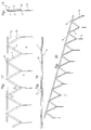
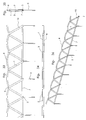
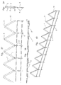
- Figures 1, 2, 3 and 4 show a spiral border with square section (14) free, in front, top, side and perspective respectively.
- Figures 5, 6, 7 and 8 show a platinum spiral rim (15) free, in front, top, side and perspective view.
- Figures 9, 10, 11 and 12 show a spiral rim of round bar (16) free, in front, top, side and perspective respectively.
- Figures 13, 14, 15 and 16 show a spiral border with lugs (5) anchoring, in front view, top, side and perspective respectively.
- Figures 17, 18, 19 and 20 show a spiral border with lugs (5) for anchoring and an upper railing (6), in front view, top, side and perspective respectively.
- Figures 21, 22, 23 and 24 show a spiral border with tabs (5) for anchoring and a lower beam (7), in front, top, side and perspective respectively.
- Figures 25, 26, 27 and 28 show a spiral border with lugs (5) for anchoring and an upper corrugated handrail (8), in front, top, side and perspective respectively.
- Figures 29, 30, 31 and 32 show a spiral border with an upper railing (6), a lower spar (7) and anchor tabs (5), in front, top, side and perspective respectively .
- Figures 33, 34, 35 and 36 show a spiral border with a corrugated upper balustrade (8), a lower spar (7) and anchor tabs (5), in front, top, side and perspective view. respectively.
- Figures 37, 38, 39 and 40 show a spiral border with a lower double grid of longitudinal members (9) and lugs (5) for anchoring, in front, top, side and perspective respectively.
- Figures 41, 42, 43 and 44 show a spiral border with double corrugated upper handrail (8 y 10) and lugs (5) anchor, in front, top, side and perspective respectively.
- Figures 45, 46, 47 and 48 show a spiral border with a double corrugated handrail (8 y 10), a lower spar (7) and anchor legs (5), in front, top, side and in perspective respectively.
- Figures 49, 50, 51 and 52 show a symmetrical double spiral border (15 y 17) with lugs (5) for anchoring, in front, top, side and perspective respectively.
- Figures 53, 54, 55, and 56 show an asymmetrical double-spiral border (15 and 18) of different height with a balustrade upper (6) common and amounts (12) at the ends, in front, top, side and perspective respectively.
- FIGS. 57, 58, 59 and 60 show an asymmetric double-spiral border (15 and 18) of different height with a common upper balustrade (6) and anchoring tabs (5), in front, upper, lateral view and in perspective respectively.
- the bar (14), ( Figures 1-4), in square section version, preferably with a section between 30 y 480 mm 2 , which constitutes the spiral evolves by folding consecutively on itself in two parallel planes, alternating straight strands (1) preferably between 100 mm and 400 mm, alternately aligned on two parallel planes (2), with other curved (3) radius maximum, preferably 25 mm which are vertices which in turn deviate the trajectory of straight strands, forming the angle (4) of development of the spiral preferably between 45 ° - 90 °.
- spiral versions although shown in flat platinum (15), they may be mounted on anchoring tabs (5) which attach to the lower corners of the spiral folds on all or in part or only at the extremities or alternating between them, and which are nested or lashed to the ground by any of the means mechanical means, or as shown in Figures 53-56 by means of uprights (12) at each end with interlocking lugs (13).
Landscapes
- Engineering & Computer Science (AREA)
- Mechanical Engineering (AREA)
- Architecture (AREA)
- Civil Engineering (AREA)
- Structural Engineering (AREA)
- Steps, Ramps, And Handrails (AREA)
Priority Applications (1)
| Application Number | Priority Date | Filing Date | Title |
|---|---|---|---|
| EP06380057A EP1837455A1 (de) | 2006-03-23 | 2006-03-23 | Dekorativer Abschluss aus Schmiedestahl mit der Form einer ebenen, endlosen Spirale und Herstellungsverfahren hierfür |
Applications Claiming Priority (1)
| Application Number | Priority Date | Filing Date | Title |
|---|---|---|---|
| EP06380057A EP1837455A1 (de) | 2006-03-23 | 2006-03-23 | Dekorativer Abschluss aus Schmiedestahl mit der Form einer ebenen, endlosen Spirale und Herstellungsverfahren hierfür |
Publications (1)
| Publication Number | Publication Date |
|---|---|
| EP1837455A1 true EP1837455A1 (de) | 2007-09-26 |
Family
ID=36942203
Family Applications (1)
| Application Number | Title | Priority Date | Filing Date |
|---|---|---|---|
| EP06380057A Withdrawn EP1837455A1 (de) | 2006-03-23 | 2006-03-23 | Dekorativer Abschluss aus Schmiedestahl mit der Form einer ebenen, endlosen Spirale und Herstellungsverfahren hierfür |
Country Status (1)
| Country | Link |
|---|---|
| EP (1) | EP1837455A1 (de) |
Cited By (2)
| Publication number | Priority date | Publication date | Assignee | Title |
|---|---|---|---|---|
| CN102896259A (zh) * | 2011-07-25 | 2013-01-30 | 中铁二局股份有限公司 | 一种“8”字形格栅的加工方法 |
| CN117300117A (zh) * | 2023-11-13 | 2023-12-29 | 湖南泰嘉智能科技有限公司 | 一种高速钢刀头颗粒的制备方法及带锯条的制造方法 |
Citations (4)
| Publication number | Priority date | Publication date | Assignee | Title |
|---|---|---|---|---|
| GB1137002A (en) * | 1965-09-13 | 1968-12-18 | Swyftite Ltd | A dropper for use with wire fencing |
| FR2134057A1 (en) * | 1971-04-21 | 1972-12-01 | Datz Hermann | Grille forming machine - forms grilles composed of upper and lower support profiles with intermediate welded zig zag elements |
| US4643400A (en) * | 1980-01-11 | 1987-02-17 | Beta Engineering And Development Ltd. | Trip-wire guiding device and protective fence including same |
| EP1316658A1 (de) * | 2001-11-29 | 2003-06-04 | Corinne Boutteau | Drahtgeflecht-Zaunpaneel mit dekorativer Randbordierung |
-
2006
- 2006-03-23 EP EP06380057A patent/EP1837455A1/de not_active Withdrawn
Patent Citations (4)
| Publication number | Priority date | Publication date | Assignee | Title |
|---|---|---|---|---|
| GB1137002A (en) * | 1965-09-13 | 1968-12-18 | Swyftite Ltd | A dropper for use with wire fencing |
| FR2134057A1 (en) * | 1971-04-21 | 1972-12-01 | Datz Hermann | Grille forming machine - forms grilles composed of upper and lower support profiles with intermediate welded zig zag elements |
| US4643400A (en) * | 1980-01-11 | 1987-02-17 | Beta Engineering And Development Ltd. | Trip-wire guiding device and protective fence including same |
| EP1316658A1 (de) * | 2001-11-29 | 2003-06-04 | Corinne Boutteau | Drahtgeflecht-Zaunpaneel mit dekorativer Randbordierung |
Cited By (2)
| Publication number | Priority date | Publication date | Assignee | Title |
|---|---|---|---|---|
| CN102896259A (zh) * | 2011-07-25 | 2013-01-30 | 中铁二局股份有限公司 | 一种“8”字形格栅的加工方法 |
| CN117300117A (zh) * | 2023-11-13 | 2023-12-29 | 湖南泰嘉智能科技有限公司 | 一种高速钢刀头颗粒的制备方法及带锯条的制造方法 |
Similar Documents
| Publication | Publication Date | Title |
|---|---|---|
| HUE025649T2 (en) | Scaffolding | |
| DE202006015586U1 (de) | Vertikalrahmenelement aus Metall | |
| EP1756367A1 (de) | Leichte metallverbindung für betonflächen | |
| EP1948889A1 (de) | Teleskopmast für eine faltbare struktur und derartige struktur | |
| EP1661451A1 (de) | Verbesserungen an profilierten Pfählen mit Antitorsionsprofil | |
| EP1783302A2 (de) | Verbindungsmitteln eines Abstützbeines eine Gerüstes, Abstützbein eines Gerüstes mit solchen Verbindungsmitteln | |
| FR2913707A1 (fr) | Echafaudage demontable et procede pour la pose et la depose d'un tel echaufaudage | |
| FR2921398A1 (fr) | Module pour la construction d'un escalier provisoire, escalier et procede d'installation d'un tel escalier | |
| FR2986813A1 (fr) | Structure de garde-corps | |
| BE1027537B1 (fr) | Module préfabriqué pour la construction d’un mur ou d’un muret habillé de pierres naturelles empilées façon pierres sèches | |
| EP1001090A2 (de) | Umstellbare Barriere-Elemente | |
| JP6869512B2 (ja) | 螺旋階段用踏み段 | |
| EP2489809B1 (de) | Verfahren zur Herstellung eines Strukturelements, und so hergestellte Elemente | |
| EP1316658B1 (de) | Drahtgeflecht-Zaunpaneel mit dekorativer Randbordierung | |
| FR3036419A1 (fr) | Poutrelle de ferraillage pour coffrage de mur de piscine | |
| FR3111651A1 (fr) | Coffrage à ductilité renforcée avec cage d’armatures tridimensionnelle repliable. | |
| EP1749951B1 (de) | Verlorenes Schalungselement und Module zur Herstellung eines solchen Elements | |
| EP1678389A1 (de) | Selbsttragende metallschalung mit grosser spannweite | |
| EP2722458B1 (de) | Dachrinne | |
| EP4343079B1 (de) | Wandverbindungsbeschlag mit integrierter schalung | |
| EP2547840B1 (de) | Schutzraumvorrichtung | |
| WO2003070395A1 (fr) | Procédé de fabrication d'une structure plane en treillis tubulaire pour la réalisation d'un élément d'ossature de bâtiment et notamment d'une ferme ou d'une panne | |
| FR3066516B1 (fr) | Module d'escalier pour escalier helicoidal de section hexagonale, ensemble avec au moins un tel module et escalier comportant au moins un tel ensemble | |
| EP3771788B1 (de) | Gitterpaneel mit gerade geführtem randdraht, herstellungsverfahren und zaun, der solche gitterpaneele umfasst | |
| FR2825730A1 (fr) | Procede de construction d'un ouvrage de soutenement adosse a une paroi |
Legal Events
| Date | Code | Title | Description |
|---|---|---|---|
| PUAI | Public reference made under article 153(3) epc to a published international application that has entered the european phase |
Free format text: ORIGINAL CODE: 0009012 |
|
| AK | Designated contracting states |
Kind code of ref document: A1 Designated state(s): AT BE BG CH CY CZ DE DK EE ES FI FR GB GR HU IE IS IT LI LT LU LV MC NL PL PT RO SE SI SK TR |
|
| AX | Request for extension of the european patent |
Extension state: AL BA HR MK YU |
|
| 17P | Request for examination filed |
Effective date: 20060421 |
|
| AKX | Designation fees paid |
Designated state(s): AT BE BG CH CY CZ DE DK EE ES FI FR GB GR HU IE IS IT LI LT LU LV MC NL PL PT RO SE SI SK TR |
|
| STAA | Information on the status of an ep patent application or granted ep patent |
Free format text: STATUS: THE APPLICATION HAS BEEN WITHDRAWN |
|
| 18W | Application withdrawn |
Effective date: 20100514 |