EP1837470A2 - Elément de fenêtre ou de porte doté d'un actionnement automatique - Google Patents
Elément de fenêtre ou de porte doté d'un actionnement automatique Download PDFInfo
- Publication number
- EP1837470A2 EP1837470A2 EP07104321A EP07104321A EP1837470A2 EP 1837470 A2 EP1837470 A2 EP 1837470A2 EP 07104321 A EP07104321 A EP 07104321A EP 07104321 A EP07104321 A EP 07104321A EP 1837470 A2 EP1837470 A2 EP 1837470A2
- Authority
- EP
- European Patent Office
- Prior art keywords
- window
- door element
- element according
- sash
- coupling device
- Prior art date
- Legal status (The legal status is an assumption and is not a legal conclusion. Google has not performed a legal analysis and makes no representation as to the accuracy of the status listed.)
- Granted
Links
Images



Classifications
-
- E—FIXED CONSTRUCTIONS
- E05—LOCKS; KEYS; WINDOW OR DOOR FITTINGS; SAFES
- E05F—DEVICES FOR MOVING WINGS INTO OPEN OR CLOSED POSITION; CHECKS FOR WINGS; WING FITTINGS NOT OTHERWISE PROVIDED FOR, CONCERNED WITH THE FUNCTIONING OF THE WING
- E05F11/00—Man-operated mechanisms for operating wings, including those which also operate the fastening
- E05F11/02—Man-operated mechanisms for operating wings, including those which also operate the fastening for wings in general, e.g. fanlights
- E05F11/04—Man-operated mechanisms for operating wings, including those which also operate the fastening for wings in general, e.g. fanlights with cords, chains or cables
- E05F11/06—Man-operated mechanisms for operating wings, including those which also operate the fastening for wings in general, e.g. fanlights with cords, chains or cables in guide-channels
-
- E—FIXED CONSTRUCTIONS
- E05—LOCKS; KEYS; WINDOW OR DOOR FITTINGS; SAFES
- E05F—DEVICES FOR MOVING WINGS INTO OPEN OR CLOSED POSITION; CHECKS FOR WINGS; WING FITTINGS NOT OTHERWISE PROVIDED FOR, CONCERNED WITH THE FUNCTIONING OF THE WING
- E05F15/00—Power-operated mechanisms for wings
- E05F15/60—Power-operated mechanisms for wings using electrical actuators
- E05F15/603—Power-operated mechanisms for wings using electrical actuators using rotary electromotors
- E05F15/611—Power-operated mechanisms for wings using electrical actuators using rotary electromotors for swinging wings
- E05F15/616—Power-operated mechanisms for wings using electrical actuators using rotary electromotors for swinging wings operated by push-pull mechanisms
- E05F15/619—Power-operated mechanisms for wings using electrical actuators using rotary electromotors for swinging wings operated by push-pull mechanisms using flexible or rigid rack-and-pinion arrangements
-
- E—FIXED CONSTRUCTIONS
- E05—LOCKS; KEYS; WINDOW OR DOOR FITTINGS; SAFES
- E05Y—INDEXING SCHEME ASSOCIATED WITH SUBCLASSES E05D AND E05F, RELATING TO CONSTRUCTION ELEMENTS, ELECTRIC CONTROL, POWER SUPPLY, POWER SIGNAL OR TRANSMISSION, USER INTERFACES, MOUNTING OR COUPLING, DETAILS, ACCESSORIES, AUXILIARY OPERATIONS NOT OTHERWISE PROVIDED FOR, APPLICATION THEREOF
- E05Y2201/00—Constructional elements; Accessories therefor
- E05Y2201/20—Brakes; Disengaging means; Holders; Stops; Valves; Accessories therefor
- E05Y2201/214—Disengaging means
-
- E—FIXED CONSTRUCTIONS
- E05—LOCKS; KEYS; WINDOW OR DOOR FITTINGS; SAFES
- E05Y—INDEXING SCHEME ASSOCIATED WITH SUBCLASSES E05D AND E05F, RELATING TO CONSTRUCTION ELEMENTS, ELECTRIC CONTROL, POWER SUPPLY, POWER SIGNAL OR TRANSMISSION, USER INTERFACES, MOUNTING OR COUPLING, DETAILS, ACCESSORIES, AUXILIARY OPERATIONS NOT OTHERWISE PROVIDED FOR, APPLICATION THEREOF
- E05Y2201/00—Constructional elements; Accessories therefor
- E05Y2201/20—Brakes; Disengaging means; Holders; Stops; Valves; Accessories therefor
- E05Y2201/218—Holders
-
- E—FIXED CONSTRUCTIONS
- E05—LOCKS; KEYS; WINDOW OR DOOR FITTINGS; SAFES
- E05Y—INDEXING SCHEME ASSOCIATED WITH SUBCLASSES E05D AND E05F, RELATING TO CONSTRUCTION ELEMENTS, ELECTRIC CONTROL, POWER SUPPLY, POWER SIGNAL OR TRANSMISSION, USER INTERFACES, MOUNTING OR COUPLING, DETAILS, ACCESSORIES, AUXILIARY OPERATIONS NOT OTHERWISE PROVIDED FOR, APPLICATION THEREOF
- E05Y2201/00—Constructional elements; Accessories therefor
- E05Y2201/20—Brakes; Disengaging means; Holders; Stops; Valves; Accessories therefor
- E05Y2201/23—Actuation thereof
- E05Y2201/244—Actuation thereof by manual operation
-
- E—FIXED CONSTRUCTIONS
- E05—LOCKS; KEYS; WINDOW OR DOOR FITTINGS; SAFES
- E05Y—INDEXING SCHEME ASSOCIATED WITH SUBCLASSES E05D AND E05F, RELATING TO CONSTRUCTION ELEMENTS, ELECTRIC CONTROL, POWER SUPPLY, POWER SIGNAL OR TRANSMISSION, USER INTERFACES, MOUNTING OR COUPLING, DETAILS, ACCESSORIES, AUXILIARY OPERATIONS NOT OTHERWISE PROVIDED FOR, APPLICATION THEREOF
- E05Y2201/00—Constructional elements; Accessories therefor
- E05Y2201/20—Brakes; Disengaging means; Holders; Stops; Valves; Accessories therefor
- E05Y2201/23—Actuation thereof
- E05Y2201/246—Actuation thereof by auxiliary motors, magnets, springs or weights
-
- E—FIXED CONSTRUCTIONS
- E05—LOCKS; KEYS; WINDOW OR DOOR FITTINGS; SAFES
- E05Y—INDEXING SCHEME ASSOCIATED WITH SUBCLASSES E05D AND E05F, RELATING TO CONSTRUCTION ELEMENTS, ELECTRIC CONTROL, POWER SUPPLY, POWER SIGNAL OR TRANSMISSION, USER INTERFACES, MOUNTING OR COUPLING, DETAILS, ACCESSORIES, AUXILIARY OPERATIONS NOT OTHERWISE PROVIDED FOR, APPLICATION THEREOF
- E05Y2201/00—Constructional elements; Accessories therefor
- E05Y2201/40—Motors; Magnets; Springs; Weights; Accessories therefor
- E05Y2201/46—Magnets
- E05Y2201/462—Electromagnets
-
- E—FIXED CONSTRUCTIONS
- E05—LOCKS; KEYS; WINDOW OR DOOR FITTINGS; SAFES
- E05Y—INDEXING SCHEME ASSOCIATED WITH SUBCLASSES E05D AND E05F, RELATING TO CONSTRUCTION ELEMENTS, ELECTRIC CONTROL, POWER SUPPLY, POWER SIGNAL OR TRANSMISSION, USER INTERFACES, MOUNTING OR COUPLING, DETAILS, ACCESSORIES, AUXILIARY OPERATIONS NOT OTHERWISE PROVIDED FOR, APPLICATION THEREOF
- E05Y2201/00—Constructional elements; Accessories therefor
- E05Y2201/60—Suspension or transmission members; Accessories therefor
- E05Y2201/622—Suspension or transmission members elements
- E05Y2201/644—Flexible elongated pulling elements
- E05Y2201/656—Chains
-
- E—FIXED CONSTRUCTIONS
- E05—LOCKS; KEYS; WINDOW OR DOOR FITTINGS; SAFES
- E05Y—INDEXING SCHEME ASSOCIATED WITH SUBCLASSES E05D AND E05F, RELATING TO CONSTRUCTION ELEMENTS, ELECTRIC CONTROL, POWER SUPPLY, POWER SIGNAL OR TRANSMISSION, USER INTERFACES, MOUNTING OR COUPLING, DETAILS, ACCESSORIES, AUXILIARY OPERATIONS NOT OTHERWISE PROVIDED FOR, APPLICATION THEREOF
- E05Y2201/00—Constructional elements; Accessories therefor
- E05Y2201/60—Suspension or transmission members; Accessories therefor
- E05Y2201/622—Suspension or transmission members elements
- E05Y2201/71—Toothed gearing
- E05Y2201/722—Racks
- E05Y2201/724—Flexible
-
- E—FIXED CONSTRUCTIONS
- E05—LOCKS; KEYS; WINDOW OR DOOR FITTINGS; SAFES
- E05Y—INDEXING SCHEME ASSOCIATED WITH SUBCLASSES E05D AND E05F, RELATING TO CONSTRUCTION ELEMENTS, ELECTRIC CONTROL, POWER SUPPLY, POWER SIGNAL OR TRANSMISSION, USER INTERFACES, MOUNTING OR COUPLING, DETAILS, ACCESSORIES, AUXILIARY OPERATIONS NOT OTHERWISE PROVIDED FOR, APPLICATION THEREOF
- E05Y2600/00—Mounting or coupling arrangements for elements provided for in this subclass
- E05Y2600/40—Mounting location; Visibility of the elements
- E05Y2600/41—Concealed
- E05Y2600/412—Concealed in the rabbet
-
- E—FIXED CONSTRUCTIONS
- E05—LOCKS; KEYS; WINDOW OR DOOR FITTINGS; SAFES
- E05Y—INDEXING SCHEME ASSOCIATED WITH SUBCLASSES E05D AND E05F, RELATING TO CONSTRUCTION ELEMENTS, ELECTRIC CONTROL, POWER SUPPLY, POWER SIGNAL OR TRANSMISSION, USER INTERFACES, MOUNTING OR COUPLING, DETAILS, ACCESSORIES, AUXILIARY OPERATIONS NOT OTHERWISE PROVIDED FOR, APPLICATION THEREOF
- E05Y2900/00—Application of doors, windows, wings or fittings thereof
- E05Y2900/10—Application of doors, windows, wings or fittings thereof for buildings or parts thereof
- E05Y2900/13—Type of wing
- E05Y2900/148—Windows
Definitions
- the invention relates to a window or door element according to the preamble of claim 1.
- the automatic drives are designed and arranged such that the frame and the sash are automatically pivotable about an axis of rotation relative to each other by the drive or by components of the drive.
- an electric motor drive for a Parallelausstellpper is known, which is partially arranged in the profile frame.
- the drive is coupled with a hardware system.
- the power supply is interrupted (Power failure) or in case of a defect of the drive, it is possible to decouple the automatic drive via a so-called coupling pin, which is accessible from the outside.
- This offers a possibility for emergency release, in which the window or door element can be opened manually.
- a disadvantage is the massive coupling pin, which is visibly arranged on the outside of the wing and affects the visual appearance.
- an automatic drive for the tilting operation of a turn-tilt window or a tilt-turn window is described.
- This drive is arranged between the blind and the wing frame, wherein the actual drive device is arranged with the drive housing in an advantageous manner on the casement on the axis of rotation in the corner region of the wing.
- the drive device is coupled via a shear-resistant drive chain with the frame, which makes it possible to move the sash at the side facing away from the pivot bearing - usually upper - side relative to the frame, whereby the sash pivots about its horizontal - usually lower - tilt axis becomes.
- the construction has proven itself in that respect.
- the problem is that when using the drive on a window or door element having only a single axis of rotation, no manual emergency opening of the wing is possible in case of failure of the automatic drive when the wing is in its closed position.
- the invention first has the object to solve the problems described above in a simple manner.
- the generic window or door element to be developed so that in a particularly simple manner, a mechanical unlocking of a completely closed in the closed state externally arranged drive can be realized.
- the coupling device is completely concealed lying in the movable sash, in the fixed frame or between these elements and it is designed so that it can be decoupled from a place outside the glare or sash without damaging the frame or sash.
- the coupling device does not appear optically in the closed state of the window and yet it can be decoupled in a simple manner.
- the coupling device is designed such that it can be decoupled in the closed state by a gap between the blend and the sash.
- the coupling device optical does not appear in the closed state of the window or at least to a non-relevant extent in appearance and it is additionally implemented a particularly simple way of decoupling without having to damage a frame part of the window for emergency opening.
- the coupling device is designed such that it can with the help of a mechanical Device which is inserted in the closed position of the wing in the gap between the frame and sash, manually decoupled.
- the coupling device to an actuator, which is preferably preferably via a remote control device, wirelessly operable and which is adapted to decouple the coupling device.
- the actuator is designed as an electromotive or electromagnetic actuator.
- the actuator may be designed as a fluid-operated, in particular pneumatic or hydraulic, actuator.
- the actuator of the coupling device is designed cost-effective and easy to handle as an electric or a permanent magnet.
- the coupling device is designed such that the connection of the drive between the glare and sash frame in the opening direction (x) of the wing is decoupled.
- the coupling device preferably has a movable component, which in each case manually - possibly with the aid of the tool - from a coupling position is solvable. It is advantageous if the movable component of the coupling device is movable transversely to the opening direction (x).
- the movable component of the coupling device is a pin or bolt.
- a bolt is a low-cost, easy-to-integrate into the construction and handling component.
- the bolt has securing means which prevent accidental opening. So offers itself as a securing means a clip on the bolt.
- the preferably used locking pin or pin is designed so that it is accessible from the outside; preferably with the aid of a tool.
- the coupling device builds on a slide principle and that the coupling device in the decoupled state in the opening direction of the wing can slide out of a sliding block.
- the emergency release according to the invention can be realized in a structurally particularly simple and cost-effective manner, as will be apparent in particular from the description of the preferred exemplary embodiments.
- the pin it is also conceivable for the pin to be separated by a gap between the blind and the sash frame by a short distance, e.g. protrudes by a few mm, so that it is easy to find and accessible.
- the invention allows summarized in a simple manner a nondestructive opening of the wing in case of failure of the electric motor drive even in the closed state.
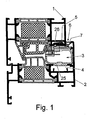
- Figure 1 shows a section (top horizontal) through a window element, which is designed as a tilting window, which has a sash 2, which is pivotally mounted on a frame 1 to a generally horizontal axis of rotation (at the bottom of the window).
- the frame 1 of the tilting window is rigidly or immovably connected to surrounding masonry or other elements.
- the pivotable sash 2 usually takes surface elements (not shown here), such. As glass, on.
- an automatic drive 3 usually provided with an electric motor.
- the drive 3 has here in a preferred embodiment, a drive housing 25 which receives the electric motor and a sliding block 5, wherein the sliding block 5 and the drive housing 25 via a drive means, in particular a chain 8, are interconnected.
- the drive housing 25 is disposed in a groove 4 of the movable sash and thus moves with the sash 2 when opening and closing the sash (see FIG. 2).
- the sliding block 5 of the drive 3 engages positively in a groove 26 of the frame 2 a. It is connected to the drive housing via the chain 8, which is designed here as a push chain, so connected that with the chain 8, the distance between the drive housing 25 and the sliding block 5 can be changed to open the window or close (Fig. 1, Fig. 2).
- the automatic drive 3 is designed for opening and closing about a horizontal axis of rotation of the wing.
- An insert of the drive to unscrew and close a wing about a vertical axis of rotation is also conceivable and readily feasible.
- a gap 6 is formed, which is sealed in the closed state by a seal 7, which may also be designed as a switching strip.
- the gap 6 offers a possibility to realize a manual access to the drive, without having to be manipulated on the frame 1 or sash 2.
- a manual nondestructive access in the closed state is therefore according to the invention via the gap. 6
- FIG. 2 shows, like FIG. 1, a section through a tilting window (in particular a skylight tilting window), but this time in an opened, tilted state.
- the stationary frame 1 is preferably fixedly connected via a shear-resistant chain 8 of the drive 3 with the sash 2, which makes it possible to move the wing about its axis of rotation.
- the gap 6 has increased by a multiple and is used e.g. for ventilation.
- the chain 8 as a link is anchored on the one hand in the wing frame side arranged drive 3 and can here, for example. be wound up or unwound over a pinion. On the other hand, the chain 8 is connected via the sliding block 5 with the frame.
- connection element 9 of the coupling member 14 with the chain 8 on the frame side relatively far towards the center of the frame, ie, it is relatively far away from the gap 6.
- the detachable coupling device according to the invention is arranged according to this specific embodiment on the side of the sliding block 5 on the frame 1.
- the coupling member 14 is formed like a slide, so that the coupling member 14 can slide out of the sliding block 5 with the connecting element 9 in the opening direction X of the wing.
- Figure 3 shows a part of the frame 1, in which the sliding block 5 is arranged or attached as a connection part for the drive.
- the sliding block 5 is designed in such a way that it has a groove channel 10 in the opening direction. Transverse thereto is a further recess 12, which - as described below - is designed for a safety pin.
- FIG. 4 shows the coupling part 14 corresponding to the sliding block 5.
- the coupling part 14 has a connection element 9, which is to be regarded as a quasi last chain link of the chain 8.
- the chain 8 is therefore permanently connected to the coupling part 14 via the connecting element 9.
- the coupling part 14 is provided with a slide-like web shape 11 so that the coupling part 14 can be inserted into (or against) the opening direction in the groove 10 of the sliding block 5.
- the entire wing is connected to the frame or decoupled.
- the coupling member 14 is positively in the sliding block 5 in desired position, so both parts with a (not shown here) component (locking pin or locking mechanism) are coupled together.
- a bolt is inserted into the transverse grooves 12 and 13, so that the coupling part 14 is positively connected to the sliding block or to the entire frame.
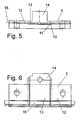
- Figure 5 shows detached in a side view of the sliding block 5, in which the coupling part 14 is inserted.
- Good to see is the T-slot-shaped configuration of the groove 10 of the Nutenstein 5, in the opening direction in the slide-like manner, the coupling member 14 is inserted with its carriage (webs) 11.
- the grooves 12 and 13 are located on an axis 15th
- FIG. 6 again shows FIG. 5, the sliding block 5 with the coupling part 14 inserted, wherein in this plan view this time a securing bolt 16 is inserted on the axis 15 in the grooves 12 and 13.
- the securing bolt 16 realizes a positive connection of sliding block 5 to the coupling part 14, so that in a simple manner a securely acting coupling device for driving the window is realized. To release this connection, the securing bolt 16 can be pulled out transversely to the opening direction of the wing.
- the securing bolt 16 is arranged in such a gap near the gap 6 that it can be easily moved out of the grooves 12 and 13 even with the wing closed. This ensures a non-destructive emergency release.
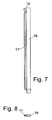
- FIGS. 7 and 8 once again show the securing bolt 16 in a plan view, it being easy to see that the securing bolt 16 additionally has a clasp 17 which has a crank 18 at its end. As a result, an unintentional slipping out of the securing bolt from the grooves 12 and 13 is prevented.
- the securing bolt which is not shown here, it can be designed in such a way that the bolt itself emerges through the gap 6 or the clasp 17 is designed in such a way that it emerges from the gap 6.
- FIGS. 9 and 10 show completely different solutions of a transverse securing of the coupling device according to the invention between the glare and sash frames.
- FIG. 9 shows the described sliding block 5 with its groove 10 in the opening direction in the manner of FIG. 3.
- the coupling member 14 is introduced here.
- the fuse is not a safety pin, which can be removed manually (as described), but via an electromotive or electromagnetic unit, via which a pin 19 can be extended and retracted.
- the releasable coupling device thus consists of the elements sliding block 5 with the not shown here, the corresponding coupling part 14, the bolt 19 and the electromotive or electromagnetic actuator, which is adapted to the bolt 19 and extend.
- a wiring through the gap 6 are arranged on the surface of the window frame.
- the bolt 19 can then be easily withdrawn by means of a battery from the outside.
- FIG. 10 shows a coupling device which can also be actuated without current.
- a rocker 21 is actuated via a permanent magnet 20 from a position outside of the window or door elements.
- the rocker 21 is designed such that on the one hand has a safety lever 22 and on the other hand, an actuating lever 23rd
- the rocker 21 is movably mounted at a pivot point in the sliding block 5 and is held by a spring element 24 in a starting position.
- the coupling member 14 (not shown here) can be pushed from the front simply on the sliding block 5 in the groove 10 and locks independently in desired position. This allows the spring-loaded movable rocker. A release is possible only with the permanent magnet 20.
- the rocker 21 is responsive to a magnetic member 25 disposed on the operating lever 23, so that the securing lever releases the coupling member 14 again.
- This embodiment allows in a simple manner without complex mounting means an emergency release of the drive, or the window.
- Figures 9 and 10 are to be understood as a schematic representation of the individual variants symbolize.
- the emergency releases can also be done differently in detail.
- the arrangement of bolts and lever in the profile direction is addressed here, which makes machining of the profiles (eg drilling) superfluous.
Landscapes
- Power-Operated Mechanisms For Wings (AREA)
Applications Claiming Priority (1)
| Application Number | Priority Date | Filing Date | Title |
|---|---|---|---|
| DE102006013332A DE102006013332A1 (de) | 2006-03-21 | 2006-03-21 | Fenster- oder Türelement mit einem automatischen Antrieb |
Publications (3)
| Publication Number | Publication Date |
|---|---|
| EP1837470A2 true EP1837470A2 (fr) | 2007-09-26 |
| EP1837470A3 EP1837470A3 (fr) | 2011-05-25 |
| EP1837470B1 EP1837470B1 (fr) | 2017-07-12 |
Family
ID=38169301
Family Applications (1)
| Application Number | Title | Priority Date | Filing Date |
|---|---|---|---|
| EP07104321.0A Active EP1837470B1 (fr) | 2006-03-21 | 2007-03-16 | Elément de fenêtre ou de porte doté d'un actionnement automatique |
Country Status (2)
| Country | Link |
|---|---|
| EP (1) | EP1837470B1 (fr) |
| DE (1) | DE102006013332A1 (fr) |
Cited By (2)
| Publication number | Priority date | Publication date | Assignee | Title |
|---|---|---|---|---|
| DE102008045071A1 (de) * | 2008-08-29 | 2010-03-18 | Roto Frank Ag | Nutensteinanordnung |
| DE102008045080A1 (de) * | 2008-08-29 | 2010-03-18 | Roto Frank Ag | Nutenstein |
Families Citing this family (6)
| Publication number | Priority date | Publication date | Assignee | Title |
|---|---|---|---|---|
| DE202008004024U1 (de) | 2008-03-20 | 2008-05-21 | SCHÜCO International KG | Antriebseinrichtung für einen Flügel eines Fensters oder einer Tür |
| DE202008006397U1 (de) | 2008-05-09 | 2008-07-17 | SCHÜCO International KG | Fenster oder Tür |
| DE202010013187U1 (de) * | 2010-12-22 | 2011-02-17 | Stg-Beikirch Industrieelektronik + Sicherheitstechnik Gmbh & Co. Kg | Anordnung einer Antriebseinheit einer Ausstell- oder Verriegelungseinrichtung |
| DE102011053767A1 (de) | 2011-09-20 | 2013-03-21 | SCHÜCO International KG | Fenster oder Tür |
| DE202015100182U1 (de) | 2015-01-15 | 2015-01-29 | SCHÜCO International KG | Antriebseinrichtung für einen Flügel eines Fensters oder einer Tür |
| DE102019205552B3 (de) | 2019-04-17 | 2020-06-04 | Geze Gmbh | Antrieb zum Öffnen und Schließen eines Flügels eines Fensters oder einer Tür |
Family Cites Families (3)
| Publication number | Priority date | Publication date | Assignee | Title |
|---|---|---|---|---|
| DE4115054C2 (de) * | 1990-05-10 | 2000-06-21 | Heinrich Schlueter | Einrichtung zur Belüftung von Fenster oder Türen mit beweglichem Flügel aufweisenden Räumen in Gebäuden |
| DE4131762C2 (de) * | 1991-09-24 | 1997-05-22 | Winkhaus Fa August | Betätigungsvorrichtung für einen Flügel eines Fensters, einer Tür, einer Lüftungsklappe oder dergleichen |
| DE102004031212B3 (de) * | 2004-06-28 | 2005-06-30 | Geze Gmbh | Flügel in einem Blendrahmen mit einem Antrieb |
-
2006
- 2006-03-21 DE DE102006013332A patent/DE102006013332A1/de not_active Withdrawn
-
2007
- 2007-03-16 EP EP07104321.0A patent/EP1837470B1/fr active Active
Cited By (3)
| Publication number | Priority date | Publication date | Assignee | Title |
|---|---|---|---|---|
| DE102008045071A1 (de) * | 2008-08-29 | 2010-03-18 | Roto Frank Ag | Nutensteinanordnung |
| DE102008045080A1 (de) * | 2008-08-29 | 2010-03-18 | Roto Frank Ag | Nutenstein |
| CN101672315B (zh) * | 2008-08-29 | 2012-09-19 | 罗托·弗兰克公司 | 凹槽螺母装置 |
Also Published As
| Publication number | Publication date |
|---|---|
| EP1837470A3 (fr) | 2011-05-25 |
| EP1837470B1 (fr) | 2017-07-12 |
| DE102006013332A1 (de) | 2007-09-27 |
Similar Documents
| Publication | Publication Date | Title |
|---|---|---|
| EP1837470B1 (fr) | Elément de fenêtre ou de porte doté d'un actionnement automatique | |
| DE19912717A1 (de) | Fenster oder Tür | |
| EP3102759B1 (fr) | Ferrure d'un battant de fenêtres ou de portes, au moins relevable et coulissant | |
| DE102004015147A1 (de) | Antriebseinrichtung | |
| EP1740792B1 (fr) | Fenetre oscillo-battante | |
| EP3759301B1 (fr) | Dispositif pour recouvrir un ouvrant coulissant ou un ouvrant coulissant et levant pouvant être déplacé d'une fenêtre ou d'une porte | |
| EP3327236B1 (fr) | Dispositif d'ouverture et/ou fermeture d'un battant | |
| EP1865130B1 (fr) | Agencement de déverrouillage d'une fenêtre, d'une porte ou analogue | |
| EP3921499B1 (fr) | Dispositif d'entraînement pivotant d'un battant | |
| EP3702555B1 (fr) | Agencement de porte ou de fenêtre doté d'une unité d'entraînement dans le bâti dormant | |
| EP1581714B1 (fr) | Fenetre oscillobattante avec un dispositif d'entrainement | |
| DE20003168U1 (de) | Parallelschiebefenster- oder -türe | |
| EP0851083B1 (fr) | Fenêtre coulissant verticalement | |
| EP0945579A2 (fr) | Dispositif de ventilation | |
| CH694510A5 (de) | Fluegelkonstruktion fuer ein Fenster oder eine Tuer. | |
| EP1493892B1 (fr) | Dispositiv de verrouillage pour une fenêtre ou un volet | |
| DE20102570U1 (de) | Drehkippbeschlag | |
| EP4421285B1 (fr) | Porte coulissante avec un battant coulissant verrouillable | |
| EP4041975A1 (fr) | Dispositif d'ouverture pour un châssis oscillo-battant d'une fenêtre ou d'une porte | |
| EP3868993A1 (fr) | Porte coulissante, en particulier une porte coulissante d'espace frigorifique | |
| EP2674560A2 (fr) | Fenêtre ou porte dotée d'un dispositif d'entraînement | |
| DE102014221290B3 (de) | Verbindungsanordnung für ein Fenster, eine Tür oder dergleichen | |
| EP3521539B1 (fr) | Fenêtre pourvue de rainure d'entraînement | |
| EP4495361B1 (fr) | Bielle réglable | |
| DE102008018086B4 (de) | Fenster, Tür oder dgl. |
Legal Events
| Date | Code | Title | Description |
|---|---|---|---|
| PUAI | Public reference made under article 153(3) epc to a published international application that has entered the european phase |
Free format text: ORIGINAL CODE: 0009012 |
|
| AK | Designated contracting states |
Kind code of ref document: A2 Designated state(s): AT BE BG CH CY CZ DE DK EE ES FI FR GB GR HU IE IS IT LI LT LU LV MC MT NL PL PT RO SE SI SK TR |
|
| AX | Request for extension of the european patent |
Extension state: AL BA HR MK YU |
|
| RIN1 | Information on inventor provided before grant (corrected) |
Inventor name: HANKE, CARSTEN Inventor name: WILKER, BURKHARD Inventor name: HOECKER, EITEL-FRIEDRICH |
|
| PUAL | Search report despatched |
Free format text: ORIGINAL CODE: 0009013 |
|
| AK | Designated contracting states |
Kind code of ref document: A3 Designated state(s): AT BE BG CH CY CZ DE DK EE ES FI FR GB GR HU IE IS IT LI LT LU LV MC MT NL PL PT RO SE SI SK TR |
|
| AX | Request for extension of the european patent |
Extension state: AL BA HR MK RS |
|
| 17P | Request for examination filed |
Effective date: 20111018 |
|
| AKX | Designation fees paid |
Designated state(s): AT BE BG CH CY CZ DE DK EE ES FI FR GB GR HU IE IS IT LI LT LU LV MC MT NL PL PT RO SE SI SK TR |
|
| 17Q | First examination report despatched |
Effective date: 20120621 |
|
| RIC1 | Information provided on ipc code assigned before grant |
Ipc: E05F 11/06 20060101ALI20161216BHEP Ipc: E05D 15/52 20060101AFI20161216BHEP Ipc: E05F 15/619 20150101ALI20161216BHEP |
|
| GRAP | Despatch of communication of intention to grant a patent |
Free format text: ORIGINAL CODE: EPIDOSNIGR1 |
|
| INTG | Intention to grant announced |
Effective date: 20170208 |
|
| GRAS | Grant fee paid |
Free format text: ORIGINAL CODE: EPIDOSNIGR3 |
|
| GRAA | (expected) grant |
Free format text: ORIGINAL CODE: 0009210 |
|
| AK | Designated contracting states |
Kind code of ref document: B1 Designated state(s): AT BE BG CH CY CZ DE DK EE ES FI FR GB GR HU IE IS IT LI LT LU LV MC MT NL PL PT RO SE SI SK TR |
|
| REG | Reference to a national code |
Ref country code: GB Ref legal event code: FG4D Free format text: NOT ENGLISH |
|
| REG | Reference to a national code |
Ref country code: CH Ref legal event code: EP |
|
| REG | Reference to a national code |
Ref country code: AT Ref legal event code: REF Ref document number: 908508 Country of ref document: AT Kind code of ref document: T Effective date: 20170715 |
|
| REG | Reference to a national code |
Ref country code: IE Ref legal event code: FG4D Free format text: LANGUAGE OF EP DOCUMENT: GERMAN |
|
| REG | Reference to a national code |
Ref country code: DE Ref legal event code: R096 Ref document number: 502007015746 Country of ref document: DE |
|
| REG | Reference to a national code |
Ref country code: NL Ref legal event code: MP Effective date: 20170712 |
|
| REG | Reference to a national code |
Ref country code: LT Ref legal event code: MG4D |
|
| PG25 | Lapsed in a contracting state [announced via postgrant information from national office to epo] |
Ref country code: LT Free format text: LAPSE BECAUSE OF FAILURE TO SUBMIT A TRANSLATION OF THE DESCRIPTION OR TO PAY THE FEE WITHIN THE PRESCRIBED TIME-LIMIT Effective date: 20170712 Ref country code: FI Free format text: LAPSE BECAUSE OF FAILURE TO SUBMIT A TRANSLATION OF THE DESCRIPTION OR TO PAY THE FEE WITHIN THE PRESCRIBED TIME-LIMIT Effective date: 20170712 Ref country code: NL Free format text: LAPSE BECAUSE OF FAILURE TO SUBMIT A TRANSLATION OF THE DESCRIPTION OR TO PAY THE FEE WITHIN THE PRESCRIBED TIME-LIMIT Effective date: 20170712 Ref country code: SE Free format text: LAPSE BECAUSE OF FAILURE TO SUBMIT A TRANSLATION OF THE DESCRIPTION OR TO PAY THE FEE WITHIN THE PRESCRIBED TIME-LIMIT Effective date: 20170712 |
|
| PG25 | Lapsed in a contracting state [announced via postgrant information from national office to epo] |
Ref country code: PL Free format text: LAPSE BECAUSE OF FAILURE TO SUBMIT A TRANSLATION OF THE DESCRIPTION OR TO PAY THE FEE WITHIN THE PRESCRIBED TIME-LIMIT Effective date: 20170712 Ref country code: IS Free format text: LAPSE BECAUSE OF FAILURE TO SUBMIT A TRANSLATION OF THE DESCRIPTION OR TO PAY THE FEE WITHIN THE PRESCRIBED TIME-LIMIT Effective date: 20171112 Ref country code: LV Free format text: LAPSE BECAUSE OF FAILURE TO SUBMIT A TRANSLATION OF THE DESCRIPTION OR TO PAY THE FEE WITHIN THE PRESCRIBED TIME-LIMIT Effective date: 20170712 Ref country code: GR Free format text: LAPSE BECAUSE OF FAILURE TO SUBMIT A TRANSLATION OF THE DESCRIPTION OR TO PAY THE FEE WITHIN THE PRESCRIBED TIME-LIMIT Effective date: 20171013 Ref country code: ES Free format text: LAPSE BECAUSE OF FAILURE TO SUBMIT A TRANSLATION OF THE DESCRIPTION OR TO PAY THE FEE WITHIN THE PRESCRIBED TIME-LIMIT Effective date: 20170712 Ref country code: BG Free format text: LAPSE BECAUSE OF FAILURE TO SUBMIT A TRANSLATION OF THE DESCRIPTION OR TO PAY THE FEE WITHIN THE PRESCRIBED TIME-LIMIT Effective date: 20171012 |
|
| REG | Reference to a national code |
Ref country code: DE Ref legal event code: R097 Ref document number: 502007015746 Country of ref document: DE |
|
| PG25 | Lapsed in a contracting state [announced via postgrant information from national office to epo] |
Ref country code: DK Free format text: LAPSE BECAUSE OF FAILURE TO SUBMIT A TRANSLATION OF THE DESCRIPTION OR TO PAY THE FEE WITHIN THE PRESCRIBED TIME-LIMIT Effective date: 20170712 Ref country code: CZ Free format text: LAPSE BECAUSE OF FAILURE TO SUBMIT A TRANSLATION OF THE DESCRIPTION OR TO PAY THE FEE WITHIN THE PRESCRIBED TIME-LIMIT Effective date: 20170712 Ref country code: RO Free format text: LAPSE BECAUSE OF FAILURE TO SUBMIT A TRANSLATION OF THE DESCRIPTION OR TO PAY THE FEE WITHIN THE PRESCRIBED TIME-LIMIT Effective date: 20170712 |
|
| PLBE | No opposition filed within time limit |
Free format text: ORIGINAL CODE: 0009261 |
|
| STAA | Information on the status of an ep patent application or granted ep patent |
Free format text: STATUS: NO OPPOSITION FILED WITHIN TIME LIMIT |
|
| PG25 | Lapsed in a contracting state [announced via postgrant information from national office to epo] |
Ref country code: EE Free format text: LAPSE BECAUSE OF FAILURE TO SUBMIT A TRANSLATION OF THE DESCRIPTION OR TO PAY THE FEE WITHIN THE PRESCRIBED TIME-LIMIT Effective date: 20170712 Ref country code: IT Free format text: LAPSE BECAUSE OF FAILURE TO SUBMIT A TRANSLATION OF THE DESCRIPTION OR TO PAY THE FEE WITHIN THE PRESCRIBED TIME-LIMIT Effective date: 20170712 Ref country code: SK Free format text: LAPSE BECAUSE OF FAILURE TO SUBMIT A TRANSLATION OF THE DESCRIPTION OR TO PAY THE FEE WITHIN THE PRESCRIBED TIME-LIMIT Effective date: 20170712 |
|
| 26N | No opposition filed |
Effective date: 20180413 |
|
| PG25 | Lapsed in a contracting state [announced via postgrant information from national office to epo] |
Ref country code: SI Free format text: LAPSE BECAUSE OF FAILURE TO SUBMIT A TRANSLATION OF THE DESCRIPTION OR TO PAY THE FEE WITHIN THE PRESCRIBED TIME-LIMIT Effective date: 20170712 |
|
| PG25 | Lapsed in a contracting state [announced via postgrant information from national office to epo] |
Ref country code: MT Free format text: LAPSE BECAUSE OF FAILURE TO SUBMIT A TRANSLATION OF THE DESCRIPTION OR TO PAY THE FEE WITHIN THE PRESCRIBED TIME-LIMIT Effective date: 20170712 |
|
| REG | Reference to a national code |
Ref country code: CH Ref legal event code: PL |
|
| GBPC | Gb: european patent ceased through non-payment of renewal fee |
Effective date: 20180316 |
|
| PG25 | Lapsed in a contracting state [announced via postgrant information from national office to epo] |
Ref country code: MC Free format text: LAPSE BECAUSE OF FAILURE TO SUBMIT A TRANSLATION OF THE DESCRIPTION OR TO PAY THE FEE WITHIN THE PRESCRIBED TIME-LIMIT Effective date: 20170712 |
|
| REG | Reference to a national code |
Ref country code: BE Ref legal event code: MM Effective date: 20180331 |
|
| REG | Reference to a national code |
Ref country code: IE Ref legal event code: MM4A |
|
| PG25 | Lapsed in a contracting state [announced via postgrant information from national office to epo] |
Ref country code: LU Free format text: LAPSE BECAUSE OF NON-PAYMENT OF DUE FEES Effective date: 20180316 |
|
| PG25 | Lapsed in a contracting state [announced via postgrant information from national office to epo] |
Ref country code: IE Free format text: LAPSE BECAUSE OF NON-PAYMENT OF DUE FEES Effective date: 20180316 |
|
| PG25 | Lapsed in a contracting state [announced via postgrant information from national office to epo] |
Ref country code: GB Free format text: LAPSE BECAUSE OF NON-PAYMENT OF DUE FEES Effective date: 20180316 Ref country code: CH Free format text: LAPSE BECAUSE OF NON-PAYMENT OF DUE FEES Effective date: 20180331 Ref country code: BE Free format text: LAPSE BECAUSE OF NON-PAYMENT OF DUE FEES Effective date: 20180331 Ref country code: LI Free format text: LAPSE BECAUSE OF NON-PAYMENT OF DUE FEES Effective date: 20180331 |
|
| PG25 | Lapsed in a contracting state [announced via postgrant information from national office to epo] |
Ref country code: FR Free format text: LAPSE BECAUSE OF NON-PAYMENT OF DUE FEES Effective date: 20180331 |
|
| REG | Reference to a national code |
Ref country code: AT Ref legal event code: MM01 Ref document number: 908508 Country of ref document: AT Kind code of ref document: T Effective date: 20180316 |
|
| PG25 | Lapsed in a contracting state [announced via postgrant information from national office to epo] |
Ref country code: AT Free format text: LAPSE BECAUSE OF NON-PAYMENT OF DUE FEES Effective date: 20180316 |
|
| PG25 | Lapsed in a contracting state [announced via postgrant information from national office to epo] |
Ref country code: TR Free format text: LAPSE BECAUSE OF FAILURE TO SUBMIT A TRANSLATION OF THE DESCRIPTION OR TO PAY THE FEE WITHIN THE PRESCRIBED TIME-LIMIT Effective date: 20170712 |
|
| PG25 | Lapsed in a contracting state [announced via postgrant information from national office to epo] |
Ref country code: HU Free format text: LAPSE BECAUSE OF FAILURE TO SUBMIT A TRANSLATION OF THE DESCRIPTION OR TO PAY THE FEE WITHIN THE PRESCRIBED TIME-LIMIT; INVALID AB INITIO Effective date: 20070316 Ref country code: PT Free format text: LAPSE BECAUSE OF FAILURE TO SUBMIT A TRANSLATION OF THE DESCRIPTION OR TO PAY THE FEE WITHIN THE PRESCRIBED TIME-LIMIT Effective date: 20170712 |
|
| PG25 | Lapsed in a contracting state [announced via postgrant information from national office to epo] |
Ref country code: CY Free format text: LAPSE BECAUSE OF FAILURE TO SUBMIT A TRANSLATION OF THE DESCRIPTION OR TO PAY THE FEE WITHIN THE PRESCRIBED TIME-LIMIT Effective date: 20170712 |
|
| P01 | Opt-out of the competence of the unified patent court (upc) registered |
Effective date: 20230813 |
|
| PGFP | Annual fee paid to national office [announced via postgrant information from national office to epo] |
Ref country code: DE Payment date: 20260305 Year of fee payment: 20 |