EP1837832A2 - Dispositif portable - Google Patents
Dispositif portable Download PDFInfo
- Publication number
- EP1837832A2 EP1837832A2 EP07104575A EP07104575A EP1837832A2 EP 1837832 A2 EP1837832 A2 EP 1837832A2 EP 07104575 A EP07104575 A EP 07104575A EP 07104575 A EP07104575 A EP 07104575A EP 1837832 A2 EP1837832 A2 EP 1837832A2
- Authority
- EP
- European Patent Office
- Prior art keywords
- case part
- case
- portable device
- circuit board
- cover piece
- Prior art date
- Legal status (The legal status is an assumption and is not a legal conclusion. Google has not performed a legal analysis and makes no representation as to the accuracy of the status listed.)
- Withdrawn
Links
- 239000003086 colorant Substances 0.000 claims abstract description 24
- 229920003002 synthetic resin Polymers 0.000 claims description 30
- 239000000057 synthetic resin Substances 0.000 claims description 30
- 238000004891 communication Methods 0.000 claims description 14
- 230000003595 spectral effect Effects 0.000 claims description 13
- 238000002834 transmittance Methods 0.000 claims description 11
- 229920001169 thermoplastic Polymers 0.000 claims description 5
- 239000004416 thermosoftening plastic Substances 0.000 claims description 5
- 229920005992 thermoplastic resin Polymers 0.000 claims description 4
- 238000003466 welding Methods 0.000 abstract description 39
- 238000012856 packing Methods 0.000 description 11
- 239000000049 pigment Substances 0.000 description 11
- 238000005304 joining Methods 0.000 description 9
- 238000003780 insertion Methods 0.000 description 7
- 230000037431 insertion Effects 0.000 description 7
- 229920005989 resin Polymers 0.000 description 7
- 239000011347 resin Substances 0.000 description 7
- 230000000007 visual effect Effects 0.000 description 6
- 239000006185 dispersion Substances 0.000 description 5
- 238000002347 injection Methods 0.000 description 5
- 239000007924 injection Substances 0.000 description 5
- 238000003825 pressing Methods 0.000 description 5
- 230000000717 retained effect Effects 0.000 description 5
- 238000002835 absorbance Methods 0.000 description 4
- 238000010438 heat treatment Methods 0.000 description 4
- 239000007788 liquid Substances 0.000 description 4
- -1 polyethylene Polymers 0.000 description 4
- 238000001228 spectrum Methods 0.000 description 4
- 238000010521 absorption reaction Methods 0.000 description 3
- 239000000463 material Substances 0.000 description 3
- 238000000034 method Methods 0.000 description 3
- 239000002245 particle Substances 0.000 description 3
- XKRFYHLGVUSROY-UHFFFAOYSA-N Argon Chemical compound [Ar] XKRFYHLGVUSROY-UHFFFAOYSA-N 0.000 description 2
- 239000000853 adhesive Substances 0.000 description 2
- JNDMLEXHDPKVFC-UHFFFAOYSA-N aluminum;oxygen(2-);yttrium(3+) Chemical compound [O-2].[O-2].[O-2].[Al+3].[Y+3] JNDMLEXHDPKVFC-UHFFFAOYSA-N 0.000 description 2
- 230000005540 biological transmission Effects 0.000 description 2
- 239000006229 carbon black Substances 0.000 description 2
- 229920006038 crystalline resin Polymers 0.000 description 2
- 238000001514 detection method Methods 0.000 description 2
- 229920001971 elastomer Polymers 0.000 description 2
- 230000002093 peripheral effect Effects 0.000 description 2
- 239000004417 polycarbonate Substances 0.000 description 2
- 229920000515 polycarbonate Polymers 0.000 description 2
- 229910019901 yttrium aluminum garnet Inorganic materials 0.000 description 2
- 229920000459 Nitrile rubber Polymers 0.000 description 1
- 229930182556 Polyacetal Natural products 0.000 description 1
- 239000004952 Polyamide Substances 0.000 description 1
- 239000004698 Polyethylene Substances 0.000 description 1
- 239000004743 Polypropylene Substances 0.000 description 1
- 239000004793 Polystyrene Substances 0.000 description 1
- 229920006311 Urethane elastomer Polymers 0.000 description 1
- 239000000654 additive Substances 0.000 description 1
- 230000000996 additive effect Effects 0.000 description 1
- 229910052786 argon Inorganic materials 0.000 description 1
- 230000015271 coagulation Effects 0.000 description 1
- 238000005345 coagulation Methods 0.000 description 1
- 238000004040 coloring Methods 0.000 description 1
- 230000001419 dependent effect Effects 0.000 description 1
- 238000010586 diagram Methods 0.000 description 1
- 239000000835 fiber Substances 0.000 description 1
- 239000010419 fine particle Substances 0.000 description 1
- 230000004927 fusion Effects 0.000 description 1
- 239000007789 gas Substances 0.000 description 1
- 239000011521 glass Substances 0.000 description 1
- CPBQJMYROZQQJC-UHFFFAOYSA-N helium neon Chemical compound [He].[Ne] CPBQJMYROZQQJC-UHFFFAOYSA-N 0.000 description 1
- 238000007689 inspection Methods 0.000 description 1
- 230000031700 light absorption Effects 0.000 description 1
- 238000004519 manufacturing process Methods 0.000 description 1
- 239000007769 metal material Substances 0.000 description 1
- 239000013307 optical fiber Substances 0.000 description 1
- 229920002647 polyamide Polymers 0.000 description 1
- 229920001707 polybutylene terephthalate Polymers 0.000 description 1
- 229920000573 polyethylene Polymers 0.000 description 1
- 229920000139 polyethylene terephthalate Polymers 0.000 description 1
- 239000005020 polyethylene terephthalate Substances 0.000 description 1
- 229920006324 polyoxymethylene Polymers 0.000 description 1
- 229920001155 polypropylene Polymers 0.000 description 1
- 229920002223 polystyrene Polymers 0.000 description 1
- 239000010979 ruby Substances 0.000 description 1
- 229910001750 ruby Inorganic materials 0.000 description 1
- 239000004065 semiconductor Substances 0.000 description 1
- 229920002379 silicone rubber Polymers 0.000 description 1
- 238000011179 visual inspection Methods 0.000 description 1
- XLYOFNOQVPJJNP-UHFFFAOYSA-N water Substances O XLYOFNOQVPJJNP-UHFFFAOYSA-N 0.000 description 1
Images




Classifications
-
- G—PHYSICS
- G07—CHECKING-DEVICES
- G07C—TIME OR ATTENDANCE REGISTERS; REGISTERING OR INDICATING THE WORKING OF MACHINES; GENERATING RANDOM NUMBERS; VOTING OR LOTTERY APPARATUS; ARRANGEMENTS, SYSTEMS OR APPARATUS FOR CHECKING NOT PROVIDED FOR ELSEWHERE
- G07C9/00—Individual registration on entry or exit
- G07C9/00174—Electronically operated locks; Circuits therefor; Nonmechanical keys therefor, e.g. passive or active electrical keys or other data carriers without mechanical keys
- G07C9/00944—Details of construction or manufacture
-
- B—PERFORMING OPERATIONS; TRANSPORTING
- B29—WORKING OF PLASTICS; WORKING OF SUBSTANCES IN A PLASTIC STATE IN GENERAL
- B29C—SHAPING OR JOINING OF PLASTICS; SHAPING OF MATERIAL IN A PLASTIC STATE, NOT OTHERWISE PROVIDED FOR; AFTER-TREATMENT OF THE SHAPED PRODUCTS, e.g. REPAIRING
- B29C65/00—Joining or sealing of preformed parts, e.g. welding of plastics materials; Apparatus therefor
- B29C65/02—Joining or sealing of preformed parts, e.g. welding of plastics materials; Apparatus therefor by heating, with or without pressure
- B29C65/14—Joining or sealing of preformed parts, e.g. welding of plastics materials; Apparatus therefor by heating, with or without pressure using wave energy, i.e. electromagnetic radiation, or particle radiation
- B29C65/16—Laser beams
- B29C65/1629—Laser beams characterised by the way of heating the interface
- B29C65/1635—Laser beams characterised by the way of heating the interface at least passing through one of the parts to be joined, i.e. laser transmission welding
-
- B—PERFORMING OPERATIONS; TRANSPORTING
- B29—WORKING OF PLASTICS; WORKING OF SUBSTANCES IN A PLASTIC STATE IN GENERAL
- B29C—SHAPING OR JOINING OF PLASTICS; SHAPING OF MATERIAL IN A PLASTIC STATE, NOT OTHERWISE PROVIDED FOR; AFTER-TREATMENT OF THE SHAPED PRODUCTS, e.g. REPAIRING
- B29C65/00—Joining or sealing of preformed parts, e.g. welding of plastics materials; Apparatus therefor
- B29C65/02—Joining or sealing of preformed parts, e.g. welding of plastics materials; Apparatus therefor by heating, with or without pressure
- B29C65/14—Joining or sealing of preformed parts, e.g. welding of plastics materials; Apparatus therefor by heating, with or without pressure using wave energy, i.e. electromagnetic radiation, or particle radiation
- B29C65/16—Laser beams
- B29C65/1629—Laser beams characterised by the way of heating the interface
- B29C65/1654—Laser beams characterised by the way of heating the interface scanning at least one of the parts to be joined
-
- B—PERFORMING OPERATIONS; TRANSPORTING
- B29—WORKING OF PLASTICS; WORKING OF SUBSTANCES IN A PLASTIC STATE IN GENERAL
- B29C—SHAPING OR JOINING OF PLASTICS; SHAPING OF MATERIAL IN A PLASTIC STATE, NOT OTHERWISE PROVIDED FOR; AFTER-TREATMENT OF THE SHAPED PRODUCTS, e.g. REPAIRING
- B29C66/00—General aspects of processes or apparatus for joining preformed parts
- B29C66/50—General aspects of joining tubular articles; General aspects of joining long products, i.e. bars or profiled elements; General aspects of joining single elements to tubular articles, hollow articles or bars; General aspects of joining several hollow-preforms to form hollow or tubular articles
- B29C66/51—Joining tubular articles, profiled elements or bars; Joining single elements to tubular articles, hollow articles or bars; Joining several hollow-preforms to form hollow or tubular articles
- B29C66/54—Joining several hollow-preforms, e.g. half-shells, to form hollow articles, e.g. for making balls, containers; Joining several hollow-preforms, e.g. half-cylinders, to form tubular articles
-
- B—PERFORMING OPERATIONS; TRANSPORTING
- B29—WORKING OF PLASTICS; WORKING OF SUBSTANCES IN A PLASTIC STATE IN GENERAL
- B29C—SHAPING OR JOINING OF PLASTICS; SHAPING OF MATERIAL IN A PLASTIC STATE, NOT OTHERWISE PROVIDED FOR; AFTER-TREATMENT OF THE SHAPED PRODUCTS, e.g. REPAIRING
- B29C66/00—General aspects of processes or apparatus for joining preformed parts
- B29C66/50—General aspects of joining tubular articles; General aspects of joining long products, i.e. bars or profiled elements; General aspects of joining single elements to tubular articles, hollow articles or bars; General aspects of joining several hollow-preforms to form hollow or tubular articles
- B29C66/51—Joining tubular articles, profiled elements or bars; Joining single elements to tubular articles, hollow articles or bars; Joining several hollow-preforms to form hollow or tubular articles
- B29C66/54—Joining several hollow-preforms, e.g. half-shells, to form hollow articles, e.g. for making balls, containers; Joining several hollow-preforms, e.g. half-cylinders, to form tubular articles
- B29C66/542—Joining several hollow-preforms, e.g. half-shells, to form hollow articles, e.g. for making balls, containers; Joining several hollow-preforms, e.g. half-cylinders, to form tubular articles joining hollow covers or hollow bottoms to open ends of container bodies
-
- B—PERFORMING OPERATIONS; TRANSPORTING
- B29—WORKING OF PLASTICS; WORKING OF SUBSTANCES IN A PLASTIC STATE IN GENERAL
- B29C—SHAPING OR JOINING OF PLASTICS; SHAPING OF MATERIAL IN A PLASTIC STATE, NOT OTHERWISE PROVIDED FOR; AFTER-TREATMENT OF THE SHAPED PRODUCTS, e.g. REPAIRING
- B29C66/00—General aspects of processes or apparatus for joining preformed parts
- B29C66/50—General aspects of joining tubular articles; General aspects of joining long products, i.e. bars or profiled elements; General aspects of joining single elements to tubular articles, hollow articles or bars; General aspects of joining several hollow-preforms to form hollow or tubular articles
- B29C66/51—Joining tubular articles, profiled elements or bars; Joining single elements to tubular articles, hollow articles or bars; Joining several hollow-preforms to form hollow or tubular articles
- B29C66/54—Joining several hollow-preforms, e.g. half-shells, to form hollow articles, e.g. for making balls, containers; Joining several hollow-preforms, e.g. half-cylinders, to form tubular articles
- B29C66/543—Joining several hollow-preforms, e.g. half-shells, to form hollow articles, e.g. for making balls, containers; Joining several hollow-preforms, e.g. half-cylinders, to form tubular articles joining more than two hollow-preforms to form said hollow articles
-
- B—PERFORMING OPERATIONS; TRANSPORTING
- B29—WORKING OF PLASTICS; WORKING OF SUBSTANCES IN A PLASTIC STATE IN GENERAL
- B29C—SHAPING OR JOINING OF PLASTICS; SHAPING OF MATERIAL IN A PLASTIC STATE, NOT OTHERWISE PROVIDED FOR; AFTER-TREATMENT OF THE SHAPED PRODUCTS, e.g. REPAIRING
- B29C66/00—General aspects of processes or apparatus for joining preformed parts
- B29C66/50—General aspects of joining tubular articles; General aspects of joining long products, i.e. bars or profiled elements; General aspects of joining single elements to tubular articles, hollow articles or bars; General aspects of joining several hollow-preforms to form hollow or tubular articles
- B29C66/65—General aspects of joining tubular articles; General aspects of joining long products, i.e. bars or profiled elements; General aspects of joining single elements to tubular articles, hollow articles or bars; General aspects of joining several hollow-preforms to form hollow or tubular articles with a relative motion between the article and the welding tool
-
- B—PERFORMING OPERATIONS; TRANSPORTING
- B29—WORKING OF PLASTICS; WORKING OF SUBSTANCES IN A PLASTIC STATE IN GENERAL
- B29C—SHAPING OR JOINING OF PLASTICS; SHAPING OF MATERIAL IN A PLASTIC STATE, NOT OTHERWISE PROVIDED FOR; AFTER-TREATMENT OF THE SHAPED PRODUCTS, e.g. REPAIRING
- B29C66/00—General aspects of processes or apparatus for joining preformed parts
- B29C66/50—General aspects of joining tubular articles; General aspects of joining long products, i.e. bars or profiled elements; General aspects of joining single elements to tubular articles, hollow articles or bars; General aspects of joining several hollow-preforms to form hollow or tubular articles
- B29C66/65—General aspects of joining tubular articles; General aspects of joining long products, i.e. bars or profiled elements; General aspects of joining single elements to tubular articles, hollow articles or bars; General aspects of joining several hollow-preforms to form hollow or tubular articles with a relative motion between the article and the welding tool
- B29C66/652—General aspects of joining tubular articles; General aspects of joining long products, i.e. bars or profiled elements; General aspects of joining single elements to tubular articles, hollow articles or bars; General aspects of joining several hollow-preforms to form hollow or tubular articles with a relative motion between the article and the welding tool moving the welding tool around the fixed article
-
- B—PERFORMING OPERATIONS; TRANSPORTING
- B29—WORKING OF PLASTICS; WORKING OF SUBSTANCES IN A PLASTIC STATE IN GENERAL
- B29C—SHAPING OR JOINING OF PLASTICS; SHAPING OF MATERIAL IN A PLASTIC STATE, NOT OTHERWISE PROVIDED FOR; AFTER-TREATMENT OF THE SHAPED PRODUCTS, e.g. REPAIRING
- B29C66/00—General aspects of processes or apparatus for joining preformed parts
- B29C66/70—General aspects of processes or apparatus for joining preformed parts characterised by the composition, physical properties or the structure of the material of the parts to be joined; Joining with non-plastics material
- B29C66/73—General aspects of processes or apparatus for joining preformed parts characterised by the composition, physical properties or the structure of the material of the parts to be joined; Joining with non-plastics material characterised by the intensive physical properties of the material of the parts to be joined, by the optical properties of the material of the parts to be joined, by the extensive physical properties of the parts to be joined, by the state of the material of the parts to be joined or by the material of the parts to be joined being a thermoplastic or a thermoset
- B29C66/733—General aspects of processes or apparatus for joining preformed parts characterised by the composition, physical properties or the structure of the material of the parts to be joined; Joining with non-plastics material characterised by the intensive physical properties of the material of the parts to be joined, by the optical properties of the material of the parts to be joined, by the extensive physical properties of the parts to be joined, by the state of the material of the parts to be joined or by the material of the parts to be joined being a thermoplastic or a thermoset characterised by the optical properties of the material of the parts to be joined, e.g. fluorescence, phosphorescence
- B29C66/7332—General aspects of processes or apparatus for joining preformed parts characterised by the composition, physical properties or the structure of the material of the parts to be joined; Joining with non-plastics material characterised by the intensive physical properties of the material of the parts to be joined, by the optical properties of the material of the parts to be joined, by the extensive physical properties of the parts to be joined, by the state of the material of the parts to be joined or by the material of the parts to be joined being a thermoplastic or a thermoset characterised by the optical properties of the material of the parts to be joined, e.g. fluorescence, phosphorescence at least one of the parts to be joined being coloured
-
- B—PERFORMING OPERATIONS; TRANSPORTING
- B29—WORKING OF PLASTICS; WORKING OF SUBSTANCES IN A PLASTIC STATE IN GENERAL
- B29C—SHAPING OR JOINING OF PLASTICS; SHAPING OF MATERIAL IN A PLASTIC STATE, NOT OTHERWISE PROVIDED FOR; AFTER-TREATMENT OF THE SHAPED PRODUCTS, e.g. REPAIRING
- B29C66/00—General aspects of processes or apparatus for joining preformed parts
- B29C66/70—General aspects of processes or apparatus for joining preformed parts characterised by the composition, physical properties or the structure of the material of the parts to be joined; Joining with non-plastics material
- B29C66/73—General aspects of processes or apparatus for joining preformed parts characterised by the composition, physical properties or the structure of the material of the parts to be joined; Joining with non-plastics material characterised by the intensive physical properties of the material of the parts to be joined, by the optical properties of the material of the parts to be joined, by the extensive physical properties of the parts to be joined, by the state of the material of the parts to be joined or by the material of the parts to be joined being a thermoplastic or a thermoset
- B29C66/739—General aspects of processes or apparatus for joining preformed parts characterised by the composition, physical properties or the structure of the material of the parts to be joined; Joining with non-plastics material characterised by the intensive physical properties of the material of the parts to be joined, by the optical properties of the material of the parts to be joined, by the extensive physical properties of the parts to be joined, by the state of the material of the parts to be joined or by the material of the parts to be joined being a thermoplastic or a thermoset characterised by the material of the parts to be joined being a thermoplastic or a thermoset
- B29C66/7392—General aspects of processes or apparatus for joining preformed parts characterised by the composition, physical properties or the structure of the material of the parts to be joined; Joining with non-plastics material characterised by the intensive physical properties of the material of the parts to be joined, by the optical properties of the material of the parts to be joined, by the extensive physical properties of the parts to be joined, by the state of the material of the parts to be joined or by the material of the parts to be joined being a thermoplastic or a thermoset characterised by the material of the parts to be joined being a thermoplastic or a thermoset characterised by the material of at least one of the parts being a thermoplastic
- B29C66/73921—General aspects of processes or apparatus for joining preformed parts characterised by the composition, physical properties or the structure of the material of the parts to be joined; Joining with non-plastics material characterised by the intensive physical properties of the material of the parts to be joined, by the optical properties of the material of the parts to be joined, by the extensive physical properties of the parts to be joined, by the state of the material of the parts to be joined or by the material of the parts to be joined being a thermoplastic or a thermoset characterised by the material of the parts to be joined being a thermoplastic or a thermoset characterised by the material of at least one of the parts being a thermoplastic characterised by the materials of both parts being thermoplastics
-
- E—FIXED CONSTRUCTIONS
- E05—LOCKS; KEYS; WINDOW OR DOOR FITTINGS; SAFES
- E05B—LOCKS; ACCESSORIES THEREFOR; HANDCUFFS
- E05B19/00—Keys; Accessories therefor
- E05B19/0082—Keys or shanks being removably stored in a larger object, e.g. a remote control or a key fob
-
- B—PERFORMING OPERATIONS; TRANSPORTING
- B29—WORKING OF PLASTICS; WORKING OF SUBSTANCES IN A PLASTIC STATE IN GENERAL
- B29C—SHAPING OR JOINING OF PLASTICS; SHAPING OF MATERIAL IN A PLASTIC STATE, NOT OTHERWISE PROVIDED FOR; AFTER-TREATMENT OF THE SHAPED PRODUCTS, e.g. REPAIRING
- B29C65/00—Joining or sealing of preformed parts, e.g. welding of plastics materials; Apparatus therefor
- B29C65/02—Joining or sealing of preformed parts, e.g. welding of plastics materials; Apparatus therefor by heating, with or without pressure
- B29C65/14—Joining or sealing of preformed parts, e.g. welding of plastics materials; Apparatus therefor by heating, with or without pressure using wave energy, i.e. electromagnetic radiation, or particle radiation
- B29C65/16—Laser beams
- B29C65/1677—Laser beams making use of an absorber or impact modifier
-
- B—PERFORMING OPERATIONS; TRANSPORTING
- B29—WORKING OF PLASTICS; WORKING OF SUBSTANCES IN A PLASTIC STATE IN GENERAL
- B29C—SHAPING OR JOINING OF PLASTICS; SHAPING OF MATERIAL IN A PLASTIC STATE, NOT OTHERWISE PROVIDED FOR; AFTER-TREATMENT OF THE SHAPED PRODUCTS, e.g. REPAIRING
- B29C65/00—Joining or sealing of preformed parts, e.g. welding of plastics materials; Apparatus therefor
- B29C65/02—Joining or sealing of preformed parts, e.g. welding of plastics materials; Apparatus therefor by heating, with or without pressure
- B29C65/14—Joining or sealing of preformed parts, e.g. welding of plastics materials; Apparatus therefor by heating, with or without pressure using wave energy, i.e. electromagnetic radiation, or particle radiation
- B29C65/16—Laser beams
- B29C65/1687—Laser beams making use of light guides
-
- B—PERFORMING OPERATIONS; TRANSPORTING
- B29—WORKING OF PLASTICS; WORKING OF SUBSTANCES IN A PLASTIC STATE IN GENERAL
- B29C—SHAPING OR JOINING OF PLASTICS; SHAPING OF MATERIAL IN A PLASTIC STATE, NOT OTHERWISE PROVIDED FOR; AFTER-TREATMENT OF THE SHAPED PRODUCTS, e.g. REPAIRING
- B29C66/00—General aspects of processes or apparatus for joining preformed parts
- B29C66/70—General aspects of processes or apparatus for joining preformed parts characterised by the composition, physical properties or the structure of the material of the parts to be joined; Joining with non-plastics material
- B29C66/71—General aspects of processes or apparatus for joining preformed parts characterised by the composition, physical properties or the structure of the material of the parts to be joined; Joining with non-plastics material characterised by the composition of the plastics material of the parts to be joined
-
- B—PERFORMING OPERATIONS; TRANSPORTING
- B29—WORKING OF PLASTICS; WORKING OF SUBSTANCES IN A PLASTIC STATE IN GENERAL
- B29C—SHAPING OR JOINING OF PLASTICS; SHAPING OF MATERIAL IN A PLASTIC STATE, NOT OTHERWISE PROVIDED FOR; AFTER-TREATMENT OF THE SHAPED PRODUCTS, e.g. REPAIRING
- B29C66/00—General aspects of processes or apparatus for joining preformed parts
- B29C66/70—General aspects of processes or apparatus for joining preformed parts characterised by the composition, physical properties or the structure of the material of the parts to be joined; Joining with non-plastics material
- B29C66/73—General aspects of processes or apparatus for joining preformed parts characterised by the composition, physical properties or the structure of the material of the parts to be joined; Joining with non-plastics material characterised by the intensive physical properties of the material of the parts to be joined, by the optical properties of the material of the parts to be joined, by the extensive physical properties of the parts to be joined, by the state of the material of the parts to be joined or by the material of the parts to be joined being a thermoplastic or a thermoset
- B29C66/737—General aspects of processes or apparatus for joining preformed parts characterised by the composition, physical properties or the structure of the material of the parts to be joined; Joining with non-plastics material characterised by the intensive physical properties of the material of the parts to be joined, by the optical properties of the material of the parts to be joined, by the extensive physical properties of the parts to be joined, by the state of the material of the parts to be joined or by the material of the parts to be joined being a thermoplastic or a thermoset characterised by the state of the material of the parts to be joined
- B29C66/7377—General aspects of processes or apparatus for joining preformed parts characterised by the composition, physical properties or the structure of the material of the parts to be joined; Joining with non-plastics material characterised by the intensive physical properties of the material of the parts to be joined, by the optical properties of the material of the parts to be joined, by the extensive physical properties of the parts to be joined, by the state of the material of the parts to be joined or by the material of the parts to be joined being a thermoplastic or a thermoset characterised by the state of the material of the parts to be joined amorphous, semi-crystalline or crystalline
- B29C66/73771—General aspects of processes or apparatus for joining preformed parts characterised by the composition, physical properties or the structure of the material of the parts to be joined; Joining with non-plastics material characterised by the intensive physical properties of the material of the parts to be joined, by the optical properties of the material of the parts to be joined, by the extensive physical properties of the parts to be joined, by the state of the material of the parts to be joined or by the material of the parts to be joined being a thermoplastic or a thermoset characterised by the state of the material of the parts to be joined amorphous, semi-crystalline or crystalline the to-be-joined area of at least one of the parts to be joined being amorphous
- B29C66/73772—General aspects of processes or apparatus for joining preformed parts characterised by the composition, physical properties or the structure of the material of the parts to be joined; Joining with non-plastics material characterised by the intensive physical properties of the material of the parts to be joined, by the optical properties of the material of the parts to be joined, by the extensive physical properties of the parts to be joined, by the state of the material of the parts to be joined or by the material of the parts to be joined being a thermoplastic or a thermoset characterised by the state of the material of the parts to be joined amorphous, semi-crystalline or crystalline the to-be-joined area of at least one of the parts to be joined being amorphous the to-be-joined areas of both parts to be joined being amorphous
-
- B—PERFORMING OPERATIONS; TRANSPORTING
- B29—WORKING OF PLASTICS; WORKING OF SUBSTANCES IN A PLASTIC STATE IN GENERAL
- B29C—SHAPING OR JOINING OF PLASTICS; SHAPING OF MATERIAL IN A PLASTIC STATE, NOT OTHERWISE PROVIDED FOR; AFTER-TREATMENT OF THE SHAPED PRODUCTS, e.g. REPAIRING
- B29C66/00—General aspects of processes or apparatus for joining preformed parts
- B29C66/70—General aspects of processes or apparatus for joining preformed parts characterised by the composition, physical properties or the structure of the material of the parts to be joined; Joining with non-plastics material
- B29C66/73—General aspects of processes or apparatus for joining preformed parts characterised by the composition, physical properties or the structure of the material of the parts to be joined; Joining with non-plastics material characterised by the intensive physical properties of the material of the parts to be joined, by the optical properties of the material of the parts to be joined, by the extensive physical properties of the parts to be joined, by the state of the material of the parts to be joined or by the material of the parts to be joined being a thermoplastic or a thermoset
- B29C66/737—General aspects of processes or apparatus for joining preformed parts characterised by the composition, physical properties or the structure of the material of the parts to be joined; Joining with non-plastics material characterised by the intensive physical properties of the material of the parts to be joined, by the optical properties of the material of the parts to be joined, by the extensive physical properties of the parts to be joined, by the state of the material of the parts to be joined or by the material of the parts to be joined being a thermoplastic or a thermoset characterised by the state of the material of the parts to be joined
- B29C66/7377—General aspects of processes or apparatus for joining preformed parts characterised by the composition, physical properties or the structure of the material of the parts to be joined; Joining with non-plastics material characterised by the intensive physical properties of the material of the parts to be joined, by the optical properties of the material of the parts to be joined, by the extensive physical properties of the parts to be joined, by the state of the material of the parts to be joined or by the material of the parts to be joined being a thermoplastic or a thermoset characterised by the state of the material of the parts to be joined amorphous, semi-crystalline or crystalline
- B29C66/73775—General aspects of processes or apparatus for joining preformed parts characterised by the composition, physical properties or the structure of the material of the parts to be joined; Joining with non-plastics material characterised by the intensive physical properties of the material of the parts to be joined, by the optical properties of the material of the parts to be joined, by the extensive physical properties of the parts to be joined, by the state of the material of the parts to be joined or by the material of the parts to be joined being a thermoplastic or a thermoset characterised by the state of the material of the parts to be joined amorphous, semi-crystalline or crystalline the to-be-joined area of at least one of the parts to be joined being crystalline
- B29C66/73776—General aspects of processes or apparatus for joining preformed parts characterised by the composition, physical properties or the structure of the material of the parts to be joined; Joining with non-plastics material characterised by the intensive physical properties of the material of the parts to be joined, by the optical properties of the material of the parts to be joined, by the extensive physical properties of the parts to be joined, by the state of the material of the parts to be joined or by the material of the parts to be joined being a thermoplastic or a thermoset characterised by the state of the material of the parts to be joined amorphous, semi-crystalline or crystalline the to-be-joined area of at least one of the parts to be joined being crystalline the to-be-joined areas of both parts to be joined being crystalline
-
- B—PERFORMING OPERATIONS; TRANSPORTING
- B29—WORKING OF PLASTICS; WORKING OF SUBSTANCES IN A PLASTIC STATE IN GENERAL
- B29K—INDEXING SCHEME ASSOCIATED WITH SUBCLASSES B29B, B29C OR B29D, RELATING TO MOULDING MATERIALS OR TO MATERIALS FOR MOULDS, REINFORCEMENTS, FILLERS OR PREFORMED PARTS, e.g. INSERTS
- B29K2023/00—Use of polyalkenes or derivatives thereof as moulding material
- B29K2023/04—Polymers of ethylene
- B29K2023/06—PE, i.e. polyethylene
-
- B—PERFORMING OPERATIONS; TRANSPORTING
- B29—WORKING OF PLASTICS; WORKING OF SUBSTANCES IN A PLASTIC STATE IN GENERAL
- B29K—INDEXING SCHEME ASSOCIATED WITH SUBCLASSES B29B, B29C OR B29D, RELATING TO MOULDING MATERIALS OR TO MATERIALS FOR MOULDS, REINFORCEMENTS, FILLERS OR PREFORMED PARTS, e.g. INSERTS
- B29K2023/00—Use of polyalkenes or derivatives thereof as moulding material
- B29K2023/10—Polymers of propylene
- B29K2023/12—PP, i.e. polypropylene
-
- B—PERFORMING OPERATIONS; TRANSPORTING
- B29—WORKING OF PLASTICS; WORKING OF SUBSTANCES IN A PLASTIC STATE IN GENERAL
- B29K—INDEXING SCHEME ASSOCIATED WITH SUBCLASSES B29B, B29C OR B29D, RELATING TO MOULDING MATERIALS OR TO MATERIALS FOR MOULDS, REINFORCEMENTS, FILLERS OR PREFORMED PARTS, e.g. INSERTS
- B29K2059/00—Use of polyacetals, e.g. POM, i.e. polyoxymethylene or derivatives thereof, as moulding material
-
- B—PERFORMING OPERATIONS; TRANSPORTING
- B29—WORKING OF PLASTICS; WORKING OF SUBSTANCES IN A PLASTIC STATE IN GENERAL
- B29K—INDEXING SCHEME ASSOCIATED WITH SUBCLASSES B29B, B29C OR B29D, RELATING TO MOULDING MATERIALS OR TO MATERIALS FOR MOULDS, REINFORCEMENTS, FILLERS OR PREFORMED PARTS, e.g. INSERTS
- B29K2067/00—Use of polyesters or derivatives thereof, as moulding material
- B29K2067/006—PBT, i.e. polybutylene terephthalate
-
- B—PERFORMING OPERATIONS; TRANSPORTING
- B29—WORKING OF PLASTICS; WORKING OF SUBSTANCES IN A PLASTIC STATE IN GENERAL
- B29K—INDEXING SCHEME ASSOCIATED WITH SUBCLASSES B29B, B29C OR B29D, RELATING TO MOULDING MATERIALS OR TO MATERIALS FOR MOULDS, REINFORCEMENTS, FILLERS OR PREFORMED PARTS, e.g. INSERTS
- B29K2069/00—Use of PC, i.e. polycarbonates or derivatives thereof, as moulding material
-
- B—PERFORMING OPERATIONS; TRANSPORTING
- B29—WORKING OF PLASTICS; WORKING OF SUBSTANCES IN A PLASTIC STATE IN GENERAL
- B29K—INDEXING SCHEME ASSOCIATED WITH SUBCLASSES B29B, B29C OR B29D, RELATING TO MOULDING MATERIALS OR TO MATERIALS FOR MOULDS, REINFORCEMENTS, FILLERS OR PREFORMED PARTS, e.g. INSERTS
- B29K2077/00—Use of PA, i.e. polyamides, e.g. polyesteramides or derivatives thereof, as moulding material
-
- B—PERFORMING OPERATIONS; TRANSPORTING
- B29—WORKING OF PLASTICS; WORKING OF SUBSTANCES IN A PLASTIC STATE IN GENERAL
- B29L—INDEXING SCHEME ASSOCIATED WITH SUBCLASS B29C, RELATING TO PARTICULAR ARTICLES
- B29L2031/00—Other particular articles
- B29L2031/34—Electrical apparatus, e.g. sparking plugs or parts thereof
- B29L2031/3481—Housings or casings incorporating or embedding electric or electronic elements
-
- G—PHYSICS
- G07—CHECKING-DEVICES
- G07C—TIME OR ATTENDANCE REGISTERS; REGISTERING OR INDICATING THE WORKING OF MACHINES; GENERATING RANDOM NUMBERS; VOTING OR LOTTERY APPARATUS; ARRANGEMENTS, SYSTEMS OR APPARATUS FOR CHECKING NOT PROVIDED FOR ELSEWHERE
- G07C9/00—Individual registration on entry or exit
- G07C9/00174—Electronically operated locks; Circuits therefor; Nonmechanical keys therefor, e.g. passive or active electrical keys or other data carriers without mechanical keys
- G07C9/00944—Details of construction or manufacture
- G07C2009/00952—Electronic keys comprising a mechanical key within their housing, e.g. extractable or retractable emergency key
Definitions
- the present invention relates to a portable device for performing wireless communication with a predetermined communication subject.
- Vehicles such as automobiles, nowadays often incorporate electronic key systems to improve vehicle operation convenience.
- Such an electronic key system locks and unlocks doors and enables the starting of the engine when a unique ID code transmitted from a portable device, which is carried by a user, is identical to an ID code registered in the vehicle.
- the portable device has a case for accommodating a circuit board on which various electronic components are mounted and a battery for supplying power to the electronic components on the circuit board.
- Japanese Laid-Open Patent Publication No. 2005-235837 describes an example of a case for a portable device.
- the case of the portable device is formed by a first case part and a second case part, which are fastened to each other. More specifically, the first case part has an open end. A plurality of projections are formed at predetermined intervals along the rim of the first case part at the open end.
- the second case part also has an open end. A plurality of recesses are formed in the rim of the second case part at the open end in correspondence with the projections of the first case part. The projections are engaged with the recesses to fasten the first and second case parts to each other.
- the first case part and the second case part are fastened to each other only by the engagement between the projections and the recesses.
- a person other than the user may be able to disassemble the case of the portable device in a relatively simple manner.
- Such a person may disassemble the case by disengaging the projections of the first case part from the recesses of the second case part in order to remove the circuit board from the case. If the first and second case parts are fastened again to each other after the circuit board is removed, the user would not be aware for a while of tampering with the circuit board.
- the applicants of the present invention have considered the joining of a first case part and a second case part through laser welding. This prevents disjoining of case parts from one another.
- one must break the joint between the first and second case parts.
- the first and second case parts cannot be joined together again.
- the user would become aware of tampering of the circuit board.
- the joining of the first and second case parts, which form the case for a portable device, through thermal welding has a shortcoming.
- the first and second case parts cannot be disjoined to check, for example, whether the proper circuit board in accordance with the required specification is accommodated therein.
- the specification for a circuit board incorporated in the case of a portable device, which is used to lock and unlock vehicle doors differs between vehicle types. In this manner, the welding renders inspection for mounting of the proper circuit board difficult.
- the present invention provides a case and portable device that enables simple identification of the internal component accommodated in the case even when the case if formed by thermally welding a first case part and a second case part to each other.
- the case includes a first case part, which is formed from a thermoplastic synthetic resin and capable of accommodating one of a plurality of components, and a second case part, which is formed from a thermoplastic resin and superimposed with the first case part in a state joined with the first case part.
- the plurality of components are respectively associated with a plurality of colors, and the first case part has a color associated with the accommodated predetermined component.
- a further aspect of the present invention is a portable device for performing wireless communication with a predetermined communication subject.
- the portable device includes a predetermined circuit board, on which an electronic component used to perform wireless communication is mounted, and a case, which accommodates the predetermined circuit board.
- the case includes a first case part, which is formed from a thermoplastic synthetic resin and capable of accommodating one of a plurality of circuit boards, and a second case part, which is formed from a thermoplastic resin and superimposed with the first case part in a state joined with the first case part.
- the plurality of circuit boards are respectively associated with a plurality of colors, and the first case part has a color associated with the accommodated predetermined circuit board.
- a portable device 11 which performs wireless communication with a predetermined communication subject, according to a preferred embodiment of the present invention will now be discussed.
- the portable device is used in an electronic key system together with a lock controller, which is installed in a vehicle.
- the portable device 11 receives a request signal transmitted from the lock controller.
- the portable device 11 transmits an ID signal, which contains an ID code of the portable device 11.
- the lock controller receives the ID signal from the portable device 11 and compares the ID code contained in the ID signal with an ID code of the vehicle that is stored in the lock controller. When the ID codes are identical, the lock controller unlocks the vehicle doors.
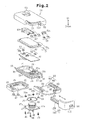
- the portable device 11 includes a case 12, which is formed by a first case part 13, a second case part 14, and a cover 81.
- the first case part 13 has an upper portion, which is open, and a lower portion.
- the second case part 14 has a lower portion, which is open and fixed to the first case part 13 so as to cover the open upper portion of the first case part 13.
- the cover 81 covers the lower portion of the first case part 13.
- the first case part 13, the second case part 14, and the cover 81 form a box as shown in Fig. 1B.
- the upper direction and lower direction of the portable device 11 will be based on the view in Fig, 1B throughout the drawings.
- the first case part 13 which is integrally injection molded from a synthetic resin, is box-shaped.
- a board compartment 21 is defined in the first case part 13.
- a square battery lid seat 22 is defined in a portion of the lower surface of the first case part 13.
- Bushing sockets 23 are formed in the four corners of the battery lid seat 22.
- a cylindrical bushing 24 is fitted into each bushing socket 23.
- a threaded hole 24a extends through the bushing 24.
- a circular and hollow battery compartment 25 is defined in the central portion of the battery lid seat 22.
- An annular groove 26 is formed between the battery compartment 25 and the four bushing sockets 23. The groove 26 receives a rubber O-ring 27.
- a through hole 25a extends through the bottom wall of the battery compartment 25.
- An opening 25b is formed in the side wall of the battery compartment 25.
- An arcuate stopper 28 is formed along the rim of the battery compartment 25 at the open end. The stopper 28 faces toward the inner side of the battery compartment 25.
- Board supports 29 are formed on the inner surfaces of the two opposing long walls of the first case part 13.
- the board supports 29 extend in a direction orthogonal to the bottom surface of the first case part 13.
- Each board support 29 has an upper end located at the same level as the upper surface of the battery compartment 25.
- a rectangular flange 30 extends along the peripheral surface of the first case part 13 at the middle of the first case part 13 in the heightwise direction.
- a plate-shaped tongue 31 extends from the portion of the flange 30 extending along the short wall of the first case part 13 located next to the battery compartment 25. The upper and lower surfaces of the tongue 31 are flush with the upper and lower surfaces of the flange 30 as viewed in Fig. 1A.
- a groove 32 having a square cross-section and functioning as a brittle portion, extends entirely across the tongue 31. Further, an engaging portion, or projection 33, extends across the lower surface of the tongue 31, as viewed in Fig. 3.
- Rails 34 having a predetermined length extend parallel to and below the flange 30 along the two opposite long walls of the first case part 13, as viewed in Fig. 3.
- a guide groove 35 is defined between the flange 30 and each rail 34.
- Recesses 36 are formed in the outer side of the two long walls and one short wall of the first case part 13 near the battery compartment 25. The recesses 36 are formed so that they are located at a level that differs from the level of the rails 34 in the vertical direction.
- the board compartment 21 of the first case part 13 accommodates a circuit board 42.
- the circuit board 42 is rectangular and shaped in correspondence with the board compartment 21.
- Push switches (micro switches) 43 are arranged in parallel in the longitudinal direction on the upper surface of the circuit board 42.
- Each push switch 43 has a housing 43a, which is fixed to the circuit board 42, and an actuator 43b, which is exposed from the housing 43a. The actuator 43b is pushed to close a contact (not shown) arranged in the housing 43a.
- the push switch 43 sends a detection signal indicating that the contact has closed to the microcomputer arranged in the circuit board 42.
- the microcomputer externally transmits control information for locking or unlocking the vehicle doors and an ID signal, which contains an ID code of the microcomputer, from a communication circuit arranged on the circuit board 42.
- a negative contact 44 and a positive contact 45 are arranged on the lower surface of the circuit board 42 as viewed in Fig. 1A.
- the negative contact 44 is exposed to the battery compartment 25 through the through hole 25a.
- the positive contact 45 is exposed to the battery compartment 25 through the opening 25b.
- the circuit board 42 is fitted into the board compartment 21 from above with the two push switches 43 facing an upward direction. Movement of the circuit board 42 into the board compartment 21 is restricted when the circuit board 42 abuts against the four board supports 29 and the upper surface of the battery compartment 25. The upper ends of the four board supports 29 and the upper surface of the battery compartment 25 are located at the same height from the bottom surface of the first case part 13. Thus, the circuit board 42 is held in a state parallel to the bottom surface of the first case part 13.
- a battery 46 which supplies the electronic components 41 on the circuit board 42 with operational power, is retained in the battery compartment 25.
- the battery 46 is a coin-type battery.
- a battery lid 47 is attached to the battery lid seat 22. More specifically, as shown in Fig. 3, the battery lid 47 is a square plate shaped in correspondence with the battery lid seat 22. Insertion holes 47a extend through the four corners of the battery lid 47. When attaching the battery lid 47 to the battery lid seat 22, the insertion holes 47a are aligned with the threaded holes 24a of the corresponding bushings 24. '
- Screws 48 are inserted into the insertion holes 47a and mated with the threaded holes 24a of the bushings 24 to fix the battery lid 47 to the battery lid seat 22.
- Each screw 48 has a head, and each insertion hole 47a includes a counterbore 47b for receiving the head of the corresponding screw 48 such that the head does not project out of the surface of the battery lid 47.
- the upper surface of the battery 46 functions as a negative electrode 46a and the peripheral surface of the battery 46 functions as a positive electrode 46b.
- the negative electrode 46a of the battery 46 is forced against the negative contact 44, which is exposed to the battery compartment 25 through the through hole 25a. This ensures that the negative electrode 46a of the battery 46 contacts the negative contact 44 under pressure.
- the positive electrode 46b of the battery 46 resiliently contacts the positive contact 45, which is exposed to the battery compartment 25 through the opening 25b.
- the second case part 14 which is integrally injection molded from a synthetic resin, is box-shaped.
- the opening of the second case part 14 defines a fitting portion 51 for receiving the first case part 13.
- the portion of the first case part 13 above the upper surface of the flange 30, as viewed in Fig. 1A, can be fitted into the fitting portion 51 in a state in which the circuit board 42 is attached to the first case part 13.
- a step 52 extends along the inner surface of the fitting portion 51.
- Two semicircular button receptacles 53 extend through the second case part 14 into the fitting portion 51. The two button receptacles 53 are spaced apart in the longitudinal direction of the second case part 14 facing opposite directions.
- the two button receptacles 53 are aligned with the actuators 43b of the push switches 43 on the circuit board 42.
- a U-shaped connection groove 54 is formed in the inner surface of the second case part 14 so as to connect the two button receptacles 53.
- the second case part 14 has two opposite long walls and two opposite short walls.
- One of the short walls and one of the long walls are thicker than the other one of the short walls and the other one of the long walls.
- An L-shaped cutaway portion 55 is formed in the corner formed by the thicker long and short walls.
- the cutaway portion 55 continuously extends from the thick long side for about two thirds of the short wall.
- an elongated groove 56 extends along the thick long wall.
- the elongated groove 56 has an end that opens to the cutaway portion 55.
- a hollow first lock member holder 57 is formed in the thick short wall.
- the first lock member holder 57 has an open portion 57a facing toward the cutaway portion 55.
- the first lock member holder 57 is in communication with the cutaway portion 55 through the open portion 57a.
- a positioning projection 57b is formed in the first lock member holder 57.
- the first lock member holder 57 of the second case part 14 retains a plate-like first lock member 58, or first lock member.
- the first lock member 58 is formed integrally from a metal material and includes a main portion 58a and an engagement portion 58b extending from the main portion 58a.
- the main portion 58a includes an insertion hole 58c for insertion of the positioning projection 57b formed in the first lock member holder 57.
- the first lock member 58 is arranged so that the positioning projection 57b is inserted into the insertion hole 58c, and the engagement portion 58b extends into the L-shaped cutaway portion 55 of the second case part 14 through the open portion 57a. Referring to Fig.
- the tongue 31 of the first case part 13 closes the opening of the first lock member holder 57 in the second case part 14.
- the first lock member 58 is retained in the first lock member holder 57.
- two semicircular push buttons 61 are respectively inserted into the two button receptacles 53 from the inner side of the second case part 14.
- the two push buttons 61 are connected to each other by a U-shaped connection member 62, which is arranged in the connection groove 54 of the second case part 14.
- the push buttons 61 and the connection member 62 are integrally injection molded from a synthetic resin.
- the push buttons 61 and the connection member 62 are flush with the inner surface of the second case part 14.
- Fig. 1 when arranged in the button receptacles 53 and connection groove 54 of the second case part 14, the push buttons 61 and the connection member 62 are flush with the inner surface of the second case part 14.
- connection member 62 includes two arms 62a, which are respectively connected to the two push buttons 61, and a link 62b connected to the arms 62a.
- the arms 62a are flexibly connected to the arms 62a so that the two push buttons 61 can be pushed independently from each other.
- a box-shaped packing 71 having an open lower portion as viewed in Fig. 1A is arranged between the first case part 13 and the second case part 14.
- the packing 71 is formed integrally from a rubber material, such as nitrile rubber, urethane rubber, or silicon rubber.
- the packing 71 includes a main body 71a, which has an open lower portion, and a lip 71b, which extends along the periphery of open end of the main body 71a.
- the main body 71a is shaped in correspondence with the inner side of the step 52 in the second case part 14, and the lip 71b is arranged on the step 52.
- the lip 71b is arranged between the open end surface of the first case part 13 and the open end surface of the fitting portion 51 in a state slightly compressed in the vertical direction. This seals the first case part 13 and the second case part 14 in a manner impervious to liquids.
- the packing 71 When the packing 71 is arranged between the first case part 13 and the second case part 14, the upper surface of the main body 71a is held in contact with the opposing inner surface of the second case part 14.
- the two push buttons 61 and the connection member 62 are held in a state accommodated in the two button receptacles 53 and the connection groove 54.
- Contact of the two push buttons 61 and the connection member 62 with the main body 71a restricts the downward movement of the two push buttons 61 and the connection member 62.
- the main body 71a resiliently deforms in an inward direction. This pushes the actuators 43b of the corresponding push switches 43 on the circuit board 42 with the main body 71a of the packing 71.
- the main body 71a separates the two button receptacles 53 and the two push buttons 61 from the inner side of the second case part 14, which accommodates the circuit board 42 in the board compartment 21.
- liquid such as water
- the main body 71a is formed integrally with the lip 71b, which is held between the open end surface of the first case part 13 and the open end surface of the fitting portion 51 in a slightly compressed state, liquid entering the button receptacles 53 through gaps formed around the push buttons 61 does not enter the inner side of the packing 71.
- the cover 81 includes a fixed cover piece 82 and a movable cover piece 83.
- the movable cover piece 83 covers the battery compartment 25 and the fixed cover piece 82 covers the remaining portion of the first case part 13.
- the fixed cover piece 82 and the movable cover piece 83 form a box having an open upper portion.
- the fixed cover piece 82 is integrally injection molded from a synthetic resin.
- the fixed cover piece 82 includes a bottom wall 82a and a U-shaped side wall 82b extending along the periphery of the bottom wall 82a.
- the fixed cover piece 82 has an open lateral side.
- a U-shaped step 84 extends along the inner surface of the side wall 82b.
- Three projections 85 are formed on the inner surfaces of the side wall 83b. The projections 85 are arranged in correspondence with the three recesses 36 of the first case part 13.
- One of the two opposing short walls of the fixed cover piece 82 is thicker than the other one.
- An elongated groove 86 is formed in the thicker short wall.
- the elongated groove 86 has an open end at the open lateral side of the fixed cover piece 82. Further, the elongated groove 86 has a width that is the same as that of the elongated groove 56 in the second case part 14.
- the fixed cover piece 82 is joined with the first case part 13, and the three projections 85 are engaged with the three recesses 36 to fasten the fixed cover piece 82 to the first case part 13.
- the movable cover piece 83 is integrally injection molded from a synthetic resin.
- the movable cover piece 83 includes a bottom wall 83a and a U-shaped side wall 83b extending along the periphery of the bottom wall 82a.
- the movable cover piece 83 has an open lateral side.
- One of the two opposing long walls of the movable cover piece 83 is thicker than the other one.
- the movable cover piece 83 has an L-shaped cutaway portion 87 at a corner formed by the thicker long wall and the adjacent short wall. When the movable cover piece 83 is attached to the first case part 13, the cutaway portion 87 is arranged in correspondence with the cutaway portion 55 of the second case part 14.
- An elongated groove 88 extends along the thicker long wall of the movable cover piece 83. One end of the elongated groove 88 opens into the cutaway portion 87.
- a first step 89 extends along the inner side of the thicker long wall on the bottom surface of the movable cover piece 83.
- a second step 90 extends along the inner sides of the thinner long wall and the short wall on the bottom surface of the movable cover piece 83.
- a rail 91 extends parallel to the long walls along each of the steps 89 and 90. The two rails 91 are inserted into and guided by the two guide grooves 35 of the first case part 13.
- An engaged portion, or recess 92 which is engageable with the projection 33, is formed in the second step 90 in a portion corresponding to the short wall.
- the movable cover piece 83 is attached to the first case part 13 in a detachable manner by inserting the two rails 91 into the two guide grooves 35 of the first case part 13 and sliding the movable cover piece 83 toward the fixed cover piece 82.
- the movement of the movable cover piece 83 in the attaching direction is restricted by the abutment of the movable cover piece 83 against the fixed cover piece 82.
- the engagement of the rails 91 of the movable cover piece 83 with the corresponding rails 34 of the first case part 13 prevents the movable cover piece 83 from falling off the first case part 13.
- the projection 33 of the first case part 13 is engaged with the recess 92 of the movable cover piece 83. This restricts movement of the movable cover piece 83 in a detaching direction of the movable cover piece 83 and prevents the movable cover piece 83 from falling off the first case part 13.
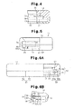
- a key plate holder 93 is defined by the elongated groove 56 of the second case part 14, the side surface of the flange 30 of the first case part 13 that is flush with the inner surface of the elongated groove 56, the elongated groove 86 of the fixed cover piece 82, and the elongated groove 88 of the movable cover piece 83. As shown in Figs.
- the L-shaped cutaway portion 55 of the second case part 14 and the L-shaped cutaway portion 87 of the movable cover piece 83 define a key inlet 94.
- the inner surfaces of the second case part 14, the first case part 13, and the movable cover piece 83 that are exposed in the key inlet 94 define a grip holder 95.
- the grip holder 95 and the key plate holder 93 define a mechanical key holder 96 for accommodating a mechanical key 101.
- the mechanical key 101 is an emergency key used when the battery is drained or when the portable device 11 is not functioning properly.
- the mechanical key 101 is used to mechanically lock and unlock a vehicle door.
- the mechanical key 101 is L-shaped and includes a key plate 102 and a grip 103 fixed to one end of the key plate 102.
- the key plate 102 has a width and length set so that it can be accommodated in the key plate holder 93 of the case 12.
- the grip 103 extends orthogonal to the key plate 102 and is accommodated in the grip holder 95 of the case 12.
- the outer surface of the grip 103 extends continuously from the outer surface of the case 12, as shown in Fig. 1B.
- the outer surface of the grip 103 serves as part of an ornamental surface of the case 12.
- the end of the grip 103 opposite the end connected to the key plate 102 includes a second lock member holder 104.
- the second lock member holder 104 is arranged to correspond with the open portion 57a of the first lock member holder 57.
- the second lock member holder 104 accommodates a second lock member 105, which is movable in the direction the grip 103 extends.
- a coil spring 106 is arranged between the second lock member 105 and the surface of the second lock member holder 104 opposed to second lock member 105. The force of the coil spring 106 constantly urges the second lock member 105 outward from the second lock member holder 104.
- a lever slot 107 which is in communication with the second lock member holder 104, is formed in the surface of the grip 103.
- a slide lever 108 extends through the lever slot 107.
- the slide lever 108 has one end fixed to the second lock member 105 and another end exposed from the grip 103.
- the slide lever 108 moves integrally with the second lock member 105.
- the movement of the second lock member 105 and the slide lever 108 in the extending direction of the grip 103 is restricted by the abutment of the slide lever 108 against the wall of the lever slot 107.
- the slide lever 108 moves the second lock member 105 between a lock position shown by the broken lines in Fig. 7C and an unlock position shown by the solid lines in Fig. 7C.
- the force of the coil spring 106 projects the second lock member 105 out of the grip 103.
- the second lock member 105 extends into the first lock member holder 57 through the open portion 57a of the case 12 and engages the engagement portion 58b of the first lock member 58.
- the second lock member 105 is located at the lock position.
- the engagement of the second lock member 105 with the engagement portion 58b of the first lock member 58 restricts the removal of the mechanical key 101 from the mechanical key holder 96.
- the second lock member 105 is moved inward into the second lock member holder 104 against the force of the coil spring 106 to disengage the second lock member 105 from the first lock member 58,
- the mechanical key 101 is removable from the mechanical key holder 96.
- the second case part 14 is first arranged on a table with the fitting portion 51 facing upwards.
- the two push buttons 61 and the connection member 62 are arranged in the two button receptacles 53 and the connection groove 54 of the second case part 14. In this state, the push buttons 61 are flush with the inner surface of the second case part 14.
- the packing 71 With its opening facing upwards, the packing 71 is arranged in the fitting portion 51. In this state, the lip 71b of the packing 71 is held on the step 52 of the second case part 14. 0
- the circuit board 42 is fitted into the board compartment 21 of the first case part 13.
- the two push switches 43 are exposed, and the negative contact 44 and positive contact 45 are arranged to correspond to the battery compartment 25.
- the first case part 13 is fitted into the fitting portion 51 of the second case part 14 with the circuit board 42 held in the board compartment 21.
- the movement of the first case part 13 into the second case part 14 is restricted when the flange 30 of the first case part 13 abuts against the open end surface of the second case part 14.
- thermal welding is performed to join the flange 30 of the first case part 13 with the open end surface of the second case part 14.
- laser welding is performed with a laser welding device to join the first case part 13 and the second case part 14.
- the battery 46 is arranged in the battery compartment 25, and the O-ring 27 is attached to the groove 26 of the battery lid seat 22. Further, the battery lid 47 is fixed to the battery lid seat 22 by fastening the screws 48 to the threaded holes 24a of the bushings 24. This holds the battery 46 in the battery compartment 25, and fixes the battery lid 47 to the first case part 13.
- the fixed cover piece 82 is placed on the first case part 13, and the three projections 85 are engaged with the three recesses 36. This fastens the fixed cover piece 82 to the first case part 13.
- the movable cover piece 83 is arranged beside the first case part 13 for attachment.
- the two rails 91 formed in the movable cover piece 83 are inserted into the two guide grooves 35 of the first case part 13.
- the movement of the movable cover piece 83 toward the fixed cover piece 82 is restricted when the side wall 83b and bottom-wall 83a of the movable cover piece 83 abut against the side wall 82b and bottom wall 82a of the fixed cover piece 82.
- the recess 92 of the movable cover piece 83 is engaged with the projection 33 of the first case part 13. This restricts removal of the movable cover piece 83 and prevents the movable cover piece 83 from moving away from the fixed cover piece 82.
- the attachment of the movable cover piece 83 to the first case part 13 forms the key plate holder 93, the grip holder 95, and the key inlet 94.
- the slide lever 108 is operated to hold the second lock member 105 at the unlock position.
- the mechanical key 101 is inserted into the key inlet 94 from the key plate 102.
- the movement of the mechanical key 101 into the mechanical key holder 96 is restricted by the abutment of the grip 103 against the outer wall of the fitting portion 51, the edge of the elongated groove 56 in the second case part 14, the flange 30 of the first case part 13, and the edge of the elongated groove 88 in the movable cover piece 83.
- the second lock member 105 is located at a position corresponding to the space between the open portion 57a of the first lock member holder 57 and the engagement portion 58b of the first lock member 58. Then, the slide lever 108 is released, and the force of the coil spring 106 moves the second lock member 105 to the lock position so that the distal end of the second lock member 105 engages the engagement portion 58b of the first lock member 58. As a result, the mechanical key 101 is prevented from falling out of the mechanical key holder 96.
- a laser welding device 111 is used to thermally weld and join the first case part 13 and the second case part 14 to each other in a superimposed state.
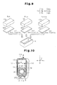
- the laser welding device 111 will first be briefly described. Referring to Fig. 8, the laser welding device 111 generates a laser beam L with a laser beam generator 112. The laser beam L travels through an optical fiber 113 and a converging lens 114. Then, the laser beam L is directed toward welded portions of two resin parts that are joined with each other.
- the laser beam source used for such laser welding may be an yttrium aluminum garnet (YAG) laser, a glass laser, a ruby laser, a helium-neon gas laser, an argon laser, a fiber laser, or a semiconductor laser. Further, the laser beam generator 112 is fixed to a housing (not shown) of the laser welding device 111.
- the converging lens 114 is driven by a drive device (not shown) and is movable in an XYZ coordinate system in the directions of the X, Y, and Z axes.
- Two parts in the preferred embodiment, the first case part 13 and the second case part 14
- the drive device is driven to move the converging lens 114 relative to the parts in order to direct the laser beam L toward the joining portions of the parts.
- the parts holder may be moved.
- the synthetic resin used to form the first case part 13 and second case part 14 may be a non-crystalline resin, such as polystyrene, polyethylene, and polycarbonate, or a crystalline resin, such as polypropylene, polybutylene terephthalate, polyethylene terephthalate, polyamide, and polyacetal. These synthetic resins are thermoplastic. In the preferred embodiment, polycarbonate is used.
- the first case part 13 transmits the laser beam L, or has a transmittance with respect to the spectrum of the laser beam L.
- the second case part 14 absorbs the spectrum of the laser beam L, or has an absorbance with respect to the spectrum of the laser beam L.
- the transmittance and absorbance of the first case part 13 and second case part 14 are dependent on the amount and dispersion of an additive (colorant), such as dye and pigment, in the synthetic resin forming the first case part 13 and second case part 14.
- pigment of a predetermined color e.g., carbon black
- the amount and dispersion of the absorption colorant for the synthetic resin is determined so that the second case part 14 has the required laser beam absorbance for generating the necessary heat.
- the laser light absorption colorant may be a pigment colorant or a dye colorant. Such pigment colorant and dye colorant may be combined to generate the necessary heat. This would enable the welding conditions to be flexible.
- Carbon black which is described above, is generally used as a pigment colorant.
- the cover 81 i.e., the fixed cover piece 82 and the movable cover piece 83
- the cover 81 is formed with the same synthetic resin as the second case part 14 and has the same color as the second case part 14.
- a dye having a color differing from the pigment added to the second case part 14 is added as a colorant to the synthetic resin that forms the first case part 13.
- the first case part 13 and the second case part 14 have different reflection characteristics (spectral reflectance) with respect to the spectrum of visible light.
- the spectral reflectance indicates the reflectance for each wavelength. That is, the spectral reflectance indicates how much light a certain object reflects for each wavelength.
- the type (color), amount, and dispersion of the pigment and dye added to the first case part 13 and the second case part 14 are determined so that the difference in the spectral reflectance between the first case part 13 and the second case part 14 exceeds 10%.
- the first case part 13 and the second case part 14 provide a visual impression of different colors. This is because the human eye perceives different colors when the reflectance of visible light differs between wavelengths.
- the difference in the spectral reflectance between the first case part 13 and the second case part 14 is less than 10%, it becomes difficult to distinguish a difference in the colors between the first case part 13 and the second case part 14.
- the type, amount, and dispersion of the pigment and dye is determined so that the transmittance of the first case part 13 with respect to visible light is 10% or greater.
- the range for the transmittance of visible light for the first case part 13 is 10% to 100%.
- the visible light transmittance is 10% or less, it becomes difficult to visually inspect welded portions (welded state) between the first case part 13 and the open end surface of the second case part 14.
- the type, amount, and dispersion of the dye for the first case part 13 are determined to ensure the required transmittance with respect to the laser beam L.
- the first case part 13 differs from the second case part 14 in that a dye is added to the synthetic resin forming the first case part 13.
- a pigment does not dissolve in a synthetic resin and is dispersed as grains (coagulations). Thus, the pigment absorbs and diffuses (reflects) the laser beam L and renders the transmission of the laser beam L difficult.
- a dye is dissolved in the synthetic resin at a molecular level. This enables uniform coloring and stabilizes the color phase.
- a dye has a high light transmission property although this is affected by the synthetic resin to which the dye is added.
- pigment is added to the synthetic resin of the second case part 14, and dye is added to the synthetic resin of the first case part 13.
- a dye does not necessarily have to be added to the synthetic resin of the first case part 13 as long as the first case part sufficiently transmits the laser beam L.
- the circuit board 42 incorporated in the portable device 11 often has a specification that differs for each vehicle type.
- the first case part 13 and the second case part 14 are joined in a manner preventing disassembly of the case 12.
- the first case part 13 and the second case part 14 may have any color as long as the required laser light transmittance and absorbance are obtained.
- first case parts 13 having different colors are prepared. Each color is associated with a circuit board 42 of a certain specification (type). Each circuit board 42 is combined with the first case part 13 having the associated color. In this state, the associated circuit board 42 and first case part 13 are joined with the second case part 14. For example, a red first case part 13a, a blue first case part 13b, and a yellow first case part 13c are prepared. A circuit board 42a of a first specification is associated with and attached to the red first case part 13a. A circuit board 42b of a second specification is associated with and attached to the blue first case part 13b. A circuit board 42c of a third specification is associated with and attached to the yellow first case part 13c.
- first case part 13 and the second case part 14 With the laser welding device 111 will now be described.
- the first case part 13 In a state in which the circuit board 42 is facing toward the second case part 14, the first case part 13 is fitted into the fitting portion 51 of the second case part 14.
- the flange 30 of the first case part 13 In a state in which the flange 30 of the first case part 13 is engaged with the open end surface of the second case part 14, the first case part 13 and second case part 14 are supported by and fixed to the parts holder of the laser welding device 111.
- a laser beam L is emitted and directed via the converging lens 114 toward the flange 30 from the first case part 13. More specifically, as shown by arrow ⁇ in Fig. 10, the laser beam L is directed toward the flange 30 while continuously moving the converging lens 114 along the flange 30 of the first case part 13. The laser beam L emitted through the converging lens 114 and transmitted through the flange 30 reaches the open end surface of the second case part 14. The energy of the laser beam L is absorbed at the portion of the open end surface of the joined with the flange 30.
- the absorption of the laser energy generates heat, which fuses the joined portions (joined surfaces) of the flange 30 and the second case part 14, Afterwards, the fused portions, or the joined portions of the flange 30 and the second case part 14, are cooled and solidified.
- the flange 30 of the first case part 13 and the open end surface of the second case part 14 may be partially joined with each other at a number of locations.
- the flange 30 functions as the joined portion of the first case part 13, and the open end surface of the second case part 14 as the joined portion of the second case part 14.
- thermally welding synthetic resin material include ultrasonic welding, vibration welding, and hot plate welding.
- Ultrasonic welding, vibration welding, and hot plate welding may be performed to join the first case part 13 and the second case part 14. However, it is preferred that laser welding be performed to join the first case part 13 and the second case part 14.
- Ultrasonic welding is performed by simultaneously applying pressure and fine vibrations to the contacting surfaces of the two resin members that are welded together. This generates high friction heat and fuses the resin. However, the heating produces fine resin particles. Further, the fine vibrations may generate vibration stress that afflicts damages to the first case part 13, the second case part 14, and the circuit board 42. Vibration welding is performed by applying pressure and friction to one of two members that are welded with each other. This generates high friction heat that fuses the resin. Although the vibration stress that is generated is less as compared with ultrasonic welding, the heating produces fine particles. Hot plate welding is performed to apply heat to the entire product with a heater plate or the like in order to cause fusion. Hot plate welding does not produce resin particles. However, heat cannot be generated locally. Thus, the application of hot plate heating to a product containing the circuit board 42 is difficult. Laser welding does not cause such problems and does not affect the first case part 13, the second case part 14, and the circuit board 42 with heat or vibrations in such a manner.
- first case part 13 may be pressed toward the second case part 14 with a pressing means, such as a roller (not shown).
- the pressing means follows the movement of the converging lens 114. Further, the pressing means continues to apply pressure until the joined portions of the first case part 13 and the second case part 14 are cooled. This prevents the generation of voids (bubbles) in the joined portions of the first case part 13 and the second case part 14.
- the preferred embodiment has the advantages described below.
- the preferred embodiment may be modified as described below.
- thermal welding laser welding
- an adhesive agent may be used to join the first case part 13 and the second case part 14.
- special bolts requiring special tools for removal such as threading bolts or one way bolts (fastening-only bolts), may be used to join the first case part 13 and the second case part 14. This would also render disjoining of the first case part 13 and the second case part 14 difficult in comparison with when using normal screws to join the first case part 13 and the second case part 14.
- the fixed cover piece 82 may be joined with the first case part 13 by an adhesive agent, special screws, or thermal welding. If the first case part 13 and the fixed cover piece 82 are disjoined at the joined portions, damages would be visible at the joined portions. This would enable the user to be aware that the circuit board 42 has been removed when finding such damages. In this manner, by inflicting two types of damages, one between the first case part 13 and the second case part 14 and another between the first case part 13 and the fixed cover piece 82, the visual effect leading to awareness of the circuit board removal is further improved.
- the first case part 13 has a color associated with the specification of the circuit board.
- the second case part 14 may be colored in association with the circuit board 42.
- the first case part 13 and the second case part 14 may have the same color, for example, if that color is associated with a certain specification of the circuit board 42.
- the present invention is embodied in a case of a portable device.
- the present invention may be embodied in a case, which incorporates electronic components, for other devices.
Landscapes
- Engineering & Computer Science (AREA)
- Mechanical Engineering (AREA)
- Physics & Mathematics (AREA)
- Optics & Photonics (AREA)
- Health & Medical Sciences (AREA)
- Electromagnetism (AREA)
- Toxicology (AREA)
- Manufacturing & Machinery (AREA)
- General Physics & Mathematics (AREA)
- Lock And Its Accessories (AREA)
- Selective Calling Equipment (AREA)
- Casings For Electric Apparatus (AREA)
Applications Claiming Priority (1)
| Application Number | Priority Date | Filing Date | Title |
|---|---|---|---|
| JP2006078330A JP2007258316A (ja) | 2006-03-22 | 2006-03-22 | ケース及び携帯機 |
Publications (1)
| Publication Number | Publication Date |
|---|---|
| EP1837832A2 true EP1837832A2 (fr) | 2007-09-26 |
Family
ID=38134789
Family Applications (1)
| Application Number | Title | Priority Date | Filing Date |
|---|---|---|---|
| EP07104575A Withdrawn EP1837832A2 (fr) | 2006-03-22 | 2007-03-21 | Dispositif portable |
Country Status (3)
| Country | Link |
|---|---|
| EP (1) | EP1837832A2 (fr) |
| JP (1) | JP2007258316A (fr) |
| AU (1) | AU2007201250A1 (fr) |
Cited By (4)
| Publication number | Priority date | Publication date | Assignee | Title |
|---|---|---|---|---|
| WO2008043719A1 (fr) * | 2006-10-09 | 2008-04-17 | Huf Hülsbeck & Fürst Gmbh & Co. Kg | Clé ÉLECTRONIQUE |
| FR2944906A1 (fr) * | 2009-04-24 | 2010-10-29 | Sarl Teleric | Appareil portable de pointage |
| CN104278887A (zh) * | 2013-07-12 | 2015-01-14 | 上海海拉电子有限公司 | 一种汽车钥匙及其安装方法 |
| CN115653400A (zh) * | 2022-10-24 | 2023-01-31 | 珠海格力电器股份有限公司 | 智能门锁、控制方法、装置、电子设备及存储介质 |
Families Citing this family (5)
| Publication number | Priority date | Publication date | Assignee | Title |
|---|---|---|---|---|
| JP5330914B2 (ja) * | 2009-07-17 | 2013-10-30 | 日立アプライアンス株式会社 | リモコン装置 |
| JP5756660B2 (ja) * | 2011-03-23 | 2015-07-29 | アイシン機工株式会社 | フューエルリッドロック装置 |
| JP6020924B2 (ja) * | 2012-10-26 | 2016-11-02 | 株式会社ホンダロック | キーユニット |
| JP2015125185A (ja) * | 2013-12-25 | 2015-07-06 | シャープ株式会社 | 携帯端末及びその製造方法 |
| KR20230117565A (ko) * | 2020-12-04 | 2023-08-08 | 소니 세미컨덕터 솔루션즈 가부시키가이샤 | 센서 모듈 |
-
2006
- 2006-03-22 JP JP2006078330A patent/JP2007258316A/ja active Pending
-
2007
- 2007-03-21 EP EP07104575A patent/EP1837832A2/fr not_active Withdrawn
- 2007-03-22 AU AU2007201250A patent/AU2007201250A1/en not_active Abandoned
Cited By (5)
| Publication number | Priority date | Publication date | Assignee | Title |
|---|---|---|---|---|
| WO2008043719A1 (fr) * | 2006-10-09 | 2008-04-17 | Huf Hülsbeck & Fürst Gmbh & Co. Kg | Clé ÉLECTRONIQUE |
| FR2944906A1 (fr) * | 2009-04-24 | 2010-10-29 | Sarl Teleric | Appareil portable de pointage |
| CN104278887A (zh) * | 2013-07-12 | 2015-01-14 | 上海海拉电子有限公司 | 一种汽车钥匙及其安装方法 |
| CN104278887B (zh) * | 2013-07-12 | 2016-12-28 | 上海海拉电子有限公司 | 一种汽车钥匙及其安装方法 |
| CN115653400A (zh) * | 2022-10-24 | 2023-01-31 | 珠海格力电器股份有限公司 | 智能门锁、控制方法、装置、电子设备及存储介质 |
Also Published As
| Publication number | Publication date |
|---|---|
| JP2007258316A (ja) | 2007-10-04 |
| AU2007201250A1 (en) | 2007-10-11 |
Similar Documents
| Publication | Publication Date | Title |
|---|---|---|
| EP1863048B1 (fr) | Dispositif portable | |
| EP1837831A2 (fr) | Étui pour dispositif portable | |
| EP1837832A2 (fr) | Dispositif portable | |
| EP1262304B1 (fr) | Procédé pour le soudage au laser par transmission de pièces en matière plastique | |
| EP1820624A2 (fr) | Boîtier, dispositif portable, et procédé de soudure laser de pièces en résine | |
| KR20010033757A (ko) | 스펙타클 프레임용 도난 방지 장치 | |
| US20180016820A1 (en) | Vehicle door lock apparatus | |
| JP7609937B2 (ja) | 少なくとも1つのカメラハウジングを車両の車両部品に固定するためのホルダベース部品、カメラハウジング、およびカメラシステム | |
| US9595149B2 (en) | Electronic key for a security system with a mechanism for releasing a battery compartment cover | |
| CN100416327C (zh) | 用于固定光学元件的方法和光学单元 | |
| US20040182937A1 (en) | Method for manufacturing a type plate for identifying an article, especially a vehicle | |
| JP7014490B2 (ja) | ドアラッチ装置 | |
| CN105283707A (zh) | 照明装置的附接结构 | |
| CN102236948A (zh) | 用于火灾报警器的壳体以及具有所述壳体的火灾报警器 | |
| JP2011111785A (ja) | 電子部品ユニット及びこれを備えた携帯用送信機 | |
| CN1722336B (zh) | 两个电器件固定装置的锁紧机构和具有该机构的电器件 | |
| CN101624074B (zh) | 装饰部件的对齐和附连系统 | |
| WO2012144113A1 (fr) | Dispositif de fixation | |
| JP2020013645A (ja) | 光センサ | |
| JP2007299803A (ja) | 電気機器の外郭構造 | |
| JP2002219257A (ja) | 遊技機の基板ケース | |
| EP4528150A1 (fr) | Dispositif d'éclairage automobile et procédé de production associé | |
| CN116699155B (zh) | 分子诊断设备及用于分子诊断设备的检测卡输送座 | |
| JP4871757B2 (ja) | 鍵材 | |
| US20260111695A1 (en) | Latch verification utilizing a scannable image |
Legal Events
| Date | Code | Title | Description |
|---|---|---|---|
| PUAI | Public reference made under article 153(3) epc to a published international application that has entered the european phase |
Free format text: ORIGINAL CODE: 0009012 |
|
| AK | Designated contracting states |
Kind code of ref document: A2 Designated state(s): AT BE BG CH CY CZ DE DK EE ES FI FR GB GR HU IE IS IT LI LT LU LV MC MT NL PL PT RO SE SI SK TR |
|
| AX | Request for extension of the european patent |
Extension state: AL BA HR MK YU |
|
| STAA | Information on the status of an ep patent application or granted ep patent |
Free format text: STATUS: THE APPLICATION HAS BEEN WITHDRAWN |
|
| 18W | Application withdrawn |
Effective date: 20090428 |