EP4528150A1 - Dispositif d'éclairage automobile et procédé de production associé - Google Patents
Dispositif d'éclairage automobile et procédé de production associé Download PDFInfo
- Publication number
- EP4528150A1 EP4528150A1 EP23199301.5A EP23199301A EP4528150A1 EP 4528150 A1 EP4528150 A1 EP 4528150A1 EP 23199301 A EP23199301 A EP 23199301A EP 4528150 A1 EP4528150 A1 EP 4528150A1
- Authority
- EP
- European Patent Office
- Prior art keywords
- rear casing
- lighting device
- transparent
- automotive lighting
- polymeric material
- Prior art date
- Legal status (The legal status is an assumption and is not a legal conclusion. Google has not performed a legal analysis and makes no representation as to the accuracy of the status listed.)
- Pending
Links
Images


Classifications
-
- F—MECHANICAL ENGINEERING; LIGHTING; HEATING; WEAPONS; BLASTING
- F21—LIGHTING
- F21S—NON-PORTABLE LIGHTING DEVICES; SYSTEMS THEREOF; VEHICLE LIGHTING DEVICES SPECIALLY ADAPTED FOR VEHICLE EXTERIORS
- F21S43/00—Signalling devices specially adapted for vehicle exteriors, e.g. brake lamps, direction indicator lights or reversing lights
- F21S43/20—Signalling devices specially adapted for vehicle exteriors, e.g. brake lamps, direction indicator lights or reversing lights characterised by refractors, transparent cover plates, light guides or filters
- F21S43/27—Attachment thereof
-
- B—PERFORMING OPERATIONS; TRANSPORTING
- B29—WORKING OF PLASTICS; WORKING OF SUBSTANCES IN A PLASTIC STATE IN GENERAL
- B29C—SHAPING OR JOINING OF PLASTICS; SHAPING OF MATERIAL IN A PLASTIC STATE, NOT OTHERWISE PROVIDED FOR; AFTER-TREATMENT OF THE SHAPED PRODUCTS, e.g. REPAIRING
- B29C65/00—Joining or sealing of preformed parts, e.g. welding of plastics materials; Apparatus therefor
- B29C65/02—Joining or sealing of preformed parts, e.g. welding of plastics materials; Apparatus therefor by heating, with or without pressure
- B29C65/14—Joining or sealing of preformed parts, e.g. welding of plastics materials; Apparatus therefor by heating, with or without pressure using wave energy, i.e. electromagnetic radiation, or particle radiation
- B29C65/16—Laser beams
- B29C65/1629—Laser beams characterised by the way of heating the interface
- B29C65/1635—Laser beams characterised by the way of heating the interface at least passing through one of the parts to be joined, i.e. laser transmission welding
-
- B—PERFORMING OPERATIONS; TRANSPORTING
- B29—WORKING OF PLASTICS; WORKING OF SUBSTANCES IN A PLASTIC STATE IN GENERAL
- B29C—SHAPING OR JOINING OF PLASTICS; SHAPING OF MATERIAL IN A PLASTIC STATE, NOT OTHERWISE PROVIDED FOR; AFTER-TREATMENT OF THE SHAPED PRODUCTS, e.g. REPAIRING
- B29C66/00—General aspects of processes or apparatus for joining preformed parts
- B29C66/01—General aspects dealing with the joint area or with the area to be joined
- B29C66/05—Particular design of joint configurations
- B29C66/10—Particular design of joint configurations particular design of the joint cross-sections
- B29C66/11—Joint cross-sections comprising a single joint-segment, i.e. one of the parts to be joined comprising a single joint-segment in the joint cross-section
- B29C66/112—Single lapped joints
- B29C66/1122—Single lap to lap joints, i.e. overlap joints
-
- B—PERFORMING OPERATIONS; TRANSPORTING
- B29—WORKING OF PLASTICS; WORKING OF SUBSTANCES IN A PLASTIC STATE IN GENERAL
- B29C—SHAPING OR JOINING OF PLASTICS; SHAPING OF MATERIAL IN A PLASTIC STATE, NOT OTHERWISE PROVIDED FOR; AFTER-TREATMENT OF THE SHAPED PRODUCTS, e.g. REPAIRING
- B29C66/00—General aspects of processes or apparatus for joining preformed parts
- B29C66/50—General aspects of joining tubular articles; General aspects of joining long products, i.e. bars or profiled elements; General aspects of joining single elements to tubular articles, hollow articles or bars; General aspects of joining several hollow-preforms to form hollow or tubular articles
- B29C66/51—Joining tubular articles, profiled elements or bars; Joining single elements to tubular articles, hollow articles or bars; Joining several hollow-preforms to form hollow or tubular articles
- B29C66/53—Joining single elements to tubular articles, hollow articles or bars
- B29C66/532—Joining single elements to the wall of tubular articles, hollow articles or bars
-
- B—PERFORMING OPERATIONS; TRANSPORTING
- B29—WORKING OF PLASTICS; WORKING OF SUBSTANCES IN A PLASTIC STATE IN GENERAL
- B29C—SHAPING OR JOINING OF PLASTICS; SHAPING OF MATERIAL IN A PLASTIC STATE, NOT OTHERWISE PROVIDED FOR; AFTER-TREATMENT OF THE SHAPED PRODUCTS, e.g. REPAIRING
- B29C66/00—General aspects of processes or apparatus for joining preformed parts
- B29C66/50—General aspects of joining tubular articles; General aspects of joining long products, i.e. bars or profiled elements; General aspects of joining single elements to tubular articles, hollow articles or bars; General aspects of joining several hollow-preforms to form hollow or tubular articles
- B29C66/51—Joining tubular articles, profiled elements or bars; Joining single elements to tubular articles, hollow articles or bars; Joining several hollow-preforms to form hollow or tubular articles
- B29C66/54—Joining several hollow-preforms, e.g. half-shells, to form hollow articles, e.g. for making balls, containers; Joining several hollow-preforms, e.g. half-cylinders, to form tubular articles
- B29C66/545—Joining several hollow-preforms, e.g. half-shells, to form hollow articles, e.g. for making balls, containers; Joining several hollow-preforms, e.g. half-cylinders, to form tubular articles one hollow-preform being placed inside the other
-
- B—PERFORMING OPERATIONS; TRANSPORTING
- B29—WORKING OF PLASTICS; WORKING OF SUBSTANCES IN A PLASTIC STATE IN GENERAL
- B29C—SHAPING OR JOINING OF PLASTICS; SHAPING OF MATERIAL IN A PLASTIC STATE, NOT OTHERWISE PROVIDED FOR; AFTER-TREATMENT OF THE SHAPED PRODUCTS, e.g. REPAIRING
- B29C66/00—General aspects of processes or apparatus for joining preformed parts
- B29C66/70—General aspects of processes or apparatus for joining preformed parts characterised by the composition, physical properties or the structure of the material of the parts to be joined; Joining with non-plastics material
- B29C66/73—General aspects of processes or apparatus for joining preformed parts characterised by the composition, physical properties or the structure of the material of the parts to be joined; Joining with non-plastics material characterised by the intensive physical properties of the material of the parts to be joined, by the optical properties of the material of the parts to be joined, by the extensive physical properties of the parts to be joined, by the state of the material of the parts to be joined or by the material of the parts to be joined being a thermoplastic or a thermoset
- B29C66/739—General aspects of processes or apparatus for joining preformed parts characterised by the composition, physical properties or the structure of the material of the parts to be joined; Joining with non-plastics material characterised by the intensive physical properties of the material of the parts to be joined, by the optical properties of the material of the parts to be joined, by the extensive physical properties of the parts to be joined, by the state of the material of the parts to be joined or by the material of the parts to be joined being a thermoplastic or a thermoset characterised by the material of the parts to be joined being a thermoplastic or a thermoset
- B29C66/7392—General aspects of processes or apparatus for joining preformed parts characterised by the composition, physical properties or the structure of the material of the parts to be joined; Joining with non-plastics material characterised by the intensive physical properties of the material of the parts to be joined, by the optical properties of the material of the parts to be joined, by the extensive physical properties of the parts to be joined, by the state of the material of the parts to be joined or by the material of the parts to be joined being a thermoplastic or a thermoset characterised by the material of the parts to be joined being a thermoplastic or a thermoset characterised by the material of at least one of the parts being a thermoplastic
- B29C66/73921—General aspects of processes or apparatus for joining preformed parts characterised by the composition, physical properties or the structure of the material of the parts to be joined; Joining with non-plastics material characterised by the intensive physical properties of the material of the parts to be joined, by the optical properties of the material of the parts to be joined, by the extensive physical properties of the parts to be joined, by the state of the material of the parts to be joined or by the material of the parts to be joined being a thermoplastic or a thermoset characterised by the material of the parts to be joined being a thermoplastic or a thermoset characterised by the material of at least one of the parts being a thermoplastic characterised by the materials of both parts being thermoplastics
-
- B—PERFORMING OPERATIONS; TRANSPORTING
- B29—WORKING OF PLASTICS; WORKING OF SUBSTANCES IN A PLASTIC STATE IN GENERAL
- B29C—SHAPING OR JOINING OF PLASTICS; SHAPING OF MATERIAL IN A PLASTIC STATE, NOT OTHERWISE PROVIDED FOR; AFTER-TREATMENT OF THE SHAPED PRODUCTS, e.g. REPAIRING
- B29C66/00—General aspects of processes or apparatus for joining preformed parts
- B29C66/80—General aspects of machine operations or constructions and parts thereof
- B29C66/81—General aspects of the pressing elements, i.e. the elements applying pressure on the parts to be joined in the area to be joined, e.g. the welding jaws or clamps
- B29C66/812—General aspects of the pressing elements, i.e. the elements applying pressure on the parts to be joined in the area to be joined, e.g. the welding jaws or clamps characterised by the composition, by the structure, by the intensive physical properties or by the optical properties of the material constituting the pressing elements, e.g. constituting the welding jaws or clamps
- B29C66/8126—General aspects of the pressing elements, i.e. the elements applying pressure on the parts to be joined in the area to be joined, e.g. the welding jaws or clamps characterised by the composition, by the structure, by the intensive physical properties or by the optical properties of the material constituting the pressing elements, e.g. constituting the welding jaws or clamps characterised by the intensive physical properties or by the optical properties of the material constituting the pressing elements, e.g. constituting the welding jaws or clamps
- B29C66/81266—Optical properties, e.g. transparency, reflectivity
- B29C66/81267—Transparent to electromagnetic radiation, e.g. to visible light
-
- F—MECHANICAL ENGINEERING; LIGHTING; HEATING; WEAPONS; BLASTING
- F21—LIGHTING
- F21S—NON-PORTABLE LIGHTING DEVICES; SYSTEMS THEREOF; VEHICLE LIGHTING DEVICES SPECIALLY ADAPTED FOR VEHICLE EXTERIORS
- F21S43/00—Signalling devices specially adapted for vehicle exteriors, e.g. brake lamps, direction indicator lights or reversing lights
- F21S43/30—Signalling devices specially adapted for vehicle exteriors, e.g. brake lamps, direction indicator lights or reversing lights characterised by reflectors
- F21S43/37—Attachment thereof
-
- F—MECHANICAL ENGINEERING; LIGHTING; HEATING; WEAPONS; BLASTING
- F21—LIGHTING
- F21S—NON-PORTABLE LIGHTING DEVICES; SYSTEMS THEREOF; VEHICLE LIGHTING DEVICES SPECIALLY ADAPTED FOR VEHICLE EXTERIORS
- F21S43/00—Signalling devices specially adapted for vehicle exteriors, e.g. brake lamps, direction indicator lights or reversing lights
- F21S43/50—Signalling devices specially adapted for vehicle exteriors, e.g. brake lamps, direction indicator lights or reversing lights characterised by aesthetic components not otherwise provided for, e.g. decorative trim, partition walls or covers
- F21S43/51—Attachment thereof
-
- B—PERFORMING OPERATIONS; TRANSPORTING
- B29—WORKING OF PLASTICS; WORKING OF SUBSTANCES IN A PLASTIC STATE IN GENERAL
- B29L—INDEXING SCHEME ASSOCIATED WITH SUBCLASS B29C, RELATING TO PARTICULAR ARTICLES
- B29L2031/00—Other particular articles
- B29L2031/30—Vehicles, e.g. ships or aircraft, or body parts thereof
- B29L2031/3055—Cars
-
- B—PERFORMING OPERATIONS; TRANSPORTING
- B29—WORKING OF PLASTICS; WORKING OF SUBSTANCES IN A PLASTIC STATE IN GENERAL
- B29L—INDEXING SCHEME ASSOCIATED WITH SUBCLASS B29C, RELATING TO PARTICULAR ARTICLES
- B29L2031/00—Other particular articles
- B29L2031/747—Lightning equipment
-
- F—MECHANICAL ENGINEERING; LIGHTING; HEATING; WEAPONS; BLASTING
- F21—LIGHTING
- F21S—NON-PORTABLE LIGHTING DEVICES; SYSTEMS THEREOF; VEHICLE LIGHTING DEVICES SPECIALLY ADAPTED FOR VEHICLE EXTERIORS
- F21S2243/00—Manufacturing details of signalling devices specially adapted for vehicle exteriors
-
- F—MECHANICAL ENGINEERING; LIGHTING; HEATING; WEAPONS; BLASTING
- F21—LIGHTING
- F21S—NON-PORTABLE LIGHTING DEVICES; SYSTEMS THEREOF; VEHICLE LIGHTING DEVICES SPECIALLY ADAPTED FOR VEHICLE EXTERIORS
- F21S41/00—Illuminating devices specially adapted for vehicle exteriors, e.g. headlamps
- F21S41/20—Illuminating devices specially adapted for vehicle exteriors, e.g. headlamps characterised by refractors, transparent cover plates, light guides or filters
- F21S41/29—Attachment thereof
-
- F—MECHANICAL ENGINEERING; LIGHTING; HEATING; WEAPONS; BLASTING
- F21—LIGHTING
- F21S—NON-PORTABLE LIGHTING DEVICES; SYSTEMS THEREOF; VEHICLE LIGHTING DEVICES SPECIALLY ADAPTED FOR VEHICLE EXTERIORS
- F21S41/00—Illuminating devices specially adapted for vehicle exteriors, e.g. headlamps
- F21S41/30—Illuminating devices specially adapted for vehicle exteriors, e.g. headlamps characterised by reflectors
- F21S41/39—Attachment thereof
-
- F—MECHANICAL ENGINEERING; LIGHTING; HEATING; WEAPONS; BLASTING
- F21—LIGHTING
- F21S—NON-PORTABLE LIGHTING DEVICES; SYSTEMS THEREOF; VEHICLE LIGHTING DEVICES SPECIALLY ADAPTED FOR VEHICLE EXTERIORS
- F21S41/00—Illuminating devices specially adapted for vehicle exteriors, e.g. headlamps
- F21S41/40—Illuminating devices specially adapted for vehicle exteriors, e.g. headlamps characterised by screens, non-reflecting members, light-shielding members or fixed shades
- F21S41/47—Attachment thereof
-
- F—MECHANICAL ENGINEERING; LIGHTING; HEATING; WEAPONS; BLASTING
- F21—LIGHTING
- F21S—NON-PORTABLE LIGHTING DEVICES; SYSTEMS THEREOF; VEHICLE LIGHTING DEVICES SPECIALLY ADAPTED FOR VEHICLE EXTERIORS
- F21S41/00—Illuminating devices specially adapted for vehicle exteriors, e.g. headlamps
- F21S41/50—Illuminating devices specially adapted for vehicle exteriors, e.g. headlamps characterised by aesthetic components not otherwise provided for, e.g. decorative trim, partition walls or covers
- F21S41/55—Attachment thereof
Definitions
- the present invention concerns an automotive lighting device and relative production method.
- the present invention preferably concerns a production method of a headlight or a taillight for cars and similar vehicles, i.e. a lighting apparatus adapted to be incorporated in a motor vehicle with the function of signalling the position, sudden deceleration and/or turning direction of the vehicle, and/or with the function of lighting the area surrounding the vehicle.
- a lighting apparatus adapted to be incorporated in a motor vehicle with the function of signalling the position, sudden deceleration and/or turning direction of the vehicle, and/or with the function of lighting the area surrounding the vehicle.
- a headlight or a taillight for cars and similar motor vehicles is conventionally a lighting device that has to be located in the front, rear or lateral part of the vehicle, and performs the function of lighting the area surrounding the vehicle and/or the function of signalling the position of the vehicle, sudden deceleration of the vehicle and/or turning direction of the vehicle, in compliance with given photometric type-approval standards.
- taillights for cars and similar motor vehicles usually comprise: a substantially basin-shaped and rigid, rear casing which is made of opaque plastic material and is structured so as to be stably recessed into a specifically provided compartment in the rear part of the vehicle body; a rigid and substantially lenticular-shaped, front half-shell which is made of plastic material, is usually provided with a number of transparent or semi-transparent sectors, optionally also having a different colour from one another, and is arranged to close the mouth of the rear casing, usually so as to surface outside the vehicle body; and a series of electrically-powered lighting assemblies that are located inside the rear casing, each immediately beneath a corresponding transparent or semi-transparent sector of the front half-shell, so as to selectively backlight the overlying transparent or semi-transparent sector of the front half-shell.
- the front half-shell has a shape substantially complementary to that of the mouth of the rear casing, and is firmly fixed to the rear casing via welding along the perimeter rim of said mouth.
- each transparent or semi-transparent sector of the front half-shell is moreover uniquely associated with a specific light signal, hence the various lighting assemblies inside the hollow housing formed/delimited by the front half-shell and by the rear casing are structured so as to emit, on command, a light beam which, once exiting from the fighting device through the corresponding transparent or semi-transparent sector of the half-shell, meets the photometric type-approval standards (light colour and distribution) established for said light signal.
- LEDs as light sources
- reflector bodies that reflect the light produced by the LEDs towards the facing transparent or semi-transparent sector of the front half-shell
- light-guide bodies that collect the light produced by the LEDs and channel it by total internal reflection towards the facing transparent or semi-transparent sector of the front half-shell.
- these lighting assemblies usually also comprise filters, corrective optics, shielding masks and/or other active and/or passive optical devices, which are capable of adapting the light beam emitted by the various LEDs to the photometric and aesthetic requirements associated with automotive use.
- these lighting assemblies are also provided with bezels, brackets and/or other support elements which are made of plastic material and which rest on the inner surface of the rear casing, and are adapted to support the printed circuit board(s) housing the LEDs, the electric wiring, the reflector body/ bodies, the light-guide body/bodies and/or the other active and/or passive optical devices that contribute to forming each lighting assembly.
- the inside of the rear casing is always provided with reference shoulders, centring pins and/or snap locking tabs, which are adapted to retain in place the various components or macro-components inside the rear casing until insertion of the self-threading screws.
- the assembly of the taillight currently requires to place the various components or macro-components that form the lighting assembly/assemblies inside the rear casing according to a given sequence, where necessary locking them temporarily in place with the aid of the reference shoulders, the centring pins and/or the snap locking tabs; and then to screw the self-threading screws in the rear casing so as to rigidly lock the various components or macro-components to the casing.
- the assembly of the taillight is then completed by welding the front half-shell onto the rim of the mouth of the rear casing.
- the assembly line of the taillight is provided with one or more inserting stations in which the various components or macro-components are placed inside the rear casing in a given sequence; one or more fixing stations in which the self-threading screws are screwed in the rear casing so as to lock the components or macro-components stably in place inside the rear casing; and a welding station in which the front half-shell is welded to the rear casing.
- the self-threading screws are some of the most costly components of the lighting device.
- the self-threading screws very often split or jam inside the automatic screwdriver, with all consequent problems.
- Aim of the present invention is to eliminate or in any case minimize the use of metal screws, so as to simplify and speed up the assembly of automotive lighting devices, also reducing the production costs thereof.
- an automotive lighting device as defined in Claim 1 and preferably, though not necessarily, in any one of the dependent claims.
- number 1 denotes as a whole an automotive lighting device, i.e. a lighting apparatus adapted to be firmly fixed on the front or rear part of the body of a motor vehicle, with the function of emitting light signals adapted to signal/indicate the position of the vehicle and/or sudden deceleration of the vehicle and/or turning direction of the vehicle during travel and/or with the function of lighting the area surrounding the vehicle.
- a lighting apparatus adapted to be firmly fixed on the front or rear part of the body of a motor vehicle, with the function of emitting light signals adapted to signal/indicate the position of the vehicle and/or sudden deceleration of the vehicle and/or turning direction of the vehicle during travel and/or with the function of lighting the area surrounding the vehicle.
- the automotive lighting device 1 is adapted to be fixed on the front or rear part of the vehicle body of a car, van, lorry, motorcycle or other similar motor vehicle, to perform the function of a headlight or taillight.
- automotive lighting device 1 may also be located on a side of the car or other similar motor vehicle.
- the automotive lighting device 1 is moreover structured so as to be stably recessed in the vehicle body (not illustrated) and to surface outside the latter.
- the automotive lighting device 1 is preferably structured to be stably recessed in the rear part of the vehicle body of a car or other similar motor vehicle.
- the automotive lighting device 1 is preferably a taillight for cars and the like.
- the automotive lighting device 1 may also be structured so as to be simply fixed cantilevered on the front, lateral or rear part of the vehicle body (not illustrated).
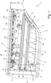
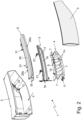
- the automotive lighting device 1 firstly comprises: a rear casing 2 with a substantially rigid and opaque structure, which has a concave shape and is adapted to be firmly fixed on the vehicle body (not illustrated), preferably inside a seat specifically realized in the rear part of the vehicle body; and a front half-shell 3 with a substantially rigid and transparent structure, separate and distinct from the rear casing, which is roughly lenticular in shape and is firmly fixed to the rear casing 2, to close the mouth of the latter, so as to form, together with the rear casing 2, a closed and internally hollow rigid housing.
- the front half-shell 3 is moreover structured so as to surface outside the vehicle body.
- the rear casing 2 is preferably shaped substantially like a basin advantageously oblong and/or has a nominal thickness preferably ranging between 1 and 4 mm (millimetres).
- the rear casing 2 preferably has a monolithic structure, and is made mainly of opaque polymeric material advantageously by injection moulding.
- the rear casing 2 is preferably made of an opaque thermoplastic polymer.
- the rear casing 2 is moreover provided, on the outer surface, with a series of fixing appendages that allow the rear casing 2 to be rigidly attached to the vehicle body (not illustrated).
- the rear casing 2 is preferably made of acrylonitrile-butadiene-styrene (ABS) or other polymeric material, advantageously filled with carbon black or other opacifying pigment.
- ABS acrylonitrile-butadiene-styrene
- the rear casing 2 could also be shaped and/or structured so as to be at least partially recessed in a seat specifically realized in the front or lateral part of the vehicle body (not illustrated), or so as to be simply fixed cantilevered on the front, lateral or rear part of the vehicle body.
- the front half-shell 3 is provided with one or more transparent or semi-transparent sectors (i.e. sectors that allow the passage of visible light), optionally also having different colours from one another, and is rigidly fixed to the rear casing 2 preferably in a fluid-tight manner.
- transparent or semi-transparent sectors i.e. sectors that allow the passage of visible light
- front half-shell 3 may also include one or more opaque sectors adjoining said transparent or semi-transparent sector(s) .
- the front half-shell 3 preferably has a shape substantially complementary to the mouth of the rear casing 2, and is fixed to the rear casing 2 along the perimeter rim of the same mouth.
- the front half-shell 3 preferably has a monolithic structure, and is preferably made mainly of a transparent polymeric material advantageously by injection moulding.
- the front half-shell 3 is preferably made of a transparent thermoplastic polymer.
- the front half-shell 3 is furthermore directly welded to the rear casing 2 in a substantially seamless way throughout the perimeter rim of the mouth of rear casing 2.
- the front half-shell 3 is preferably made of transparent polycarbonate (PC), transparent polymethylmethacrylate (PMMA) or other transparent or semi-transparent polymeric material.
- the front half-shell 3 is moreover welded to the rear casing 2 in known manner via laser welding, vibration welding or hot-plate welding.
- automotive lighting device 1 moreover comprises a series of lighting internal components, separate and distinct from the rear casing 2 and from the front half-shell 3, some of which are substantially rigid and made of polymeric material opaque to visible light.
- some of these lighting internal components made of opaque polymeric material are arranged resting on the inner surface of rear casing 2 in at least one contact area or zone, and are rigidly fixed in a non-removable manner to the rear casing 2 via at least one laser welding joint realized in said contact area.
- said laser welding joint is also substantially a spot weld.
- the rear casing 2 has, at said contact area, a small-dimensions portion made of laser-transparent polymeric material, which locally takes up the entire thickness of the rear casing 2 so as to allow the laser beam to pass through the rear casing 2 without substantial energy losses.
- the lighting internal component made of opaque polymeric material has, at said contact area, a small-dimensions limited portion made of laser-transparent polymeric material, which locally takes up the entire thickness of the internal component so as to allow the laser beam to pass through the component without substantial energy losses.
- the contact area between the rear casing 2 and the internal component made of opaque polymeric material is therefore formed/defined by a portion made of polymeric material which is opaque (to visible light) and by an adjacent portion made of laser-transparent polymeric material.
- the laser welding joint is located straddling said portion made of laser-transparent polymeric material and the adjacent portion made of opaque polymeric material.
- the rear casing 2 or, alternatively, the internal component is therefore a two-colour piece or a two-materials piece.
- the rear casing 2 and the lighting internal component are furthermore shaped/structured so as to provide, in the area of mutual contact, a shape coupling.
- the rear casing 2 and the lighting internal component made of opaque polymeric material are preferably shaped/structured so as to realize, in the area(s) or zone(s) of mutual contact, a male-female coupling.
- each lighting internal component made of opaque polymeric material is preferably provided with one or more protruding fixing pins, each of which extends parallel to a predefined insertion direction, and is adapted to arrange its distal end in abutment against the inner surface of the rear casing 2.
- the laser welding joint is preferably located at the distal end of the fixing pin, which is made of opaque polymeric material.
- each fixing pin is preferably also adapted to engage a corresponding receiving seat, which is preferably substantially cup-shaped, and is realized directly on the rear casing 2, or rather on the bottom of the rear casing 2.
- the distal end of the fixing pin is preferably adapted to rest stably on the bottom of the receiving seat, and therefore the contact area is preferably located on the bottom of said receiving seat.
- the receiving seat preferably has a shape substantially complementary to that of the distal end of the fixing pin.
- the portion made of laser-transparent polymeric material is preferably located on the bottom of said receiving seat.
- the whole receiving seat may be made of laser-transparent material.
- the fixing pins may protrude cantilevered from the bottom of the rear casing 2 and the receiving seats may be located on the internal component or components made of opaque polymeric material.
- the automotive lighting device 1 comprises one or more lighting assemblies, which is/are located inside the rear casing 2 and is/are adapted to backlight the front half-shell 3.
- each lighting assembly is preferably aligned with a corresponding transparent or semi-transparent sector of front half-shell 3, and is adapted to emit light so as to backlight said transparent or semi-transparent sector of half-shell 3, preferably separately and independently of the other lighting assemblies.
- the lighting assembly/assemblies 3 is/are preferably electrically-powered lighting assemblies that is/ are adapted to emit light on command and are advantageously also entirely accommodated within the rear casing 2.
- the/each of the lighting assemblies is furthermore structured so as to emit, on command, a light beam which, once exited from the automotive lighting device 1 through the corresponding transparent or semi-transparent sector of the half-shell 3, meets the photometric type-approval standards (light colour and distribution) established for a given light signal.
- a light beam which, once exited from the automotive lighting device 1 through the corresponding transparent or semi-transparent sector of the half-shell 3, meets the photometric type-approval standards (light colour and distribution) established for a given light signal.
- one or some lighting assemblies of automotive lighting device 1 may also emit a light beam that does not meet or must meet said photometric type-approval standards.
- the automotive lighting device 1 may also comprise one or more cameras and/or one or more photosensitive sensors and/or one or more radar devices and/or one or more LiDAR (acronym of Light Detection and Ranging) instruments and/or other supplementary electronic devices, again accommodated within the rigid housing formed/delimited by rear casing 2 and by front half-shell 3.
- LiDAR cronym of Light Detection and Ranging
- the above-mentioned lighting internal components made of opaque polymeric material contribute to forming said lighting assembly/assemblies and/or said supplementary electronic device(s).
- the or at least one of the lighting assemblies or other supplementary electronic devices preferably include one or more substantially rigid and opaque, lighting internal components which are made of opaque polymeric material, rest on the inner surface of rear casing 2 at at least one relative contact/support area or zone, and are rigidly fixed in a non-removable manner to the rear casing 2 by means of a laser welding joint realized in said contact area.
- the automotive lighting device 1 is preferably provided with three lighting assemblies separate and distinct from one another, in the following denoted by numbers 4, 5 and 6, each of which is adapted to backlight a corresponding transparent or semi-transparent sector of the front half-shell 3.
- the lighting assembly 4 preferably comprises: a reflector body 7 with a substantially rigid and opaque structure, which is located inside the rear casing 2, preferably against the bottom of the same casing, and is provided with at least one concave reflecting surface 7a that preferably has a substantially semi-parabolic profile, and is oriented so as to reflect the incident light towards the facing transparent or semi-transparent sector of front half-shell 3; and an electrically-powered light-emitting device 8 preferably with a plate-like structure, which emits light on command and is located inside the rear casing 2, beside the reflector body 7 and advantageously also very close the bottom of rear casing 2, so as to direct the light produced towards the concave reflecting surface 7a of reflector body 7.
- the reflector body 7 is made of an opaque polymeric material advantageously by injection moulding, and the concave reflecting surface 7a is preferably covered by a thin film of opaque reflecting material, advantageously of metallic type, so as to reflect the incident light.
- the reflector body 7, in addition, is structured so as to rest on the inner surface of rear casing 2 in at least one contact area 9, and is rigidly fixed/anchored to the rear casing 2 via at least one preferably substantially spotlike, laser welding joint 10 realized at the contact area 9.
- rear casing 2 and reflector body 7 are furthermore shaped/structured so as to realize, in the area of mutual contact 9, a shape coupling, or rather a male-female coupling.
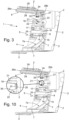
- the reflector body 7 is preferably provided with one or more protruding fixing pins 11 advantageously substantially rectilinear and optionally also tapered towards the distal end, each of which extends parallel to an insertion direction d substantially perpendicular to the bottom of the casing 2, and is adapted to engage a corresponding receiving seat 12 preferably with cup-shaped or similar structure, which is realized directly on rear casing 2, or rather on the bottom of casing 2.
- said receiving seat 12 furthermore has a shape substantially complementary to the distal end of the fixing pin 11.
- distal end of the/each fixing pin 11 is preferably structured so as to rest stably on the bottom of the relative receiving seat 12.
- the reflector body 7 is preferably made of opaque polycarbonate (PC) (a polymeric material suitable for mirror metallization), and is preferably provided with a number of concave reflecting surfaces 7a advantageously arranged aligned side by side to one another.
- PC opaque polycarbonate
- the reflector body 7 is preferably provided with a pair of reciprocally parallel and substantially frustoconical in shape, fixing pins 11 that are arranged on opposite sides of the row of concave reflecting surfaces 7a, locally substantially perpendicular to the bottom of the rear casing 2.
- Each fixing pin 11 is preferably adapted to engage a corresponding receiving seat 12 with cup-shaped structure, advantageously realized on the bottom of rear casing 2.
- each fixing pin 11 is furthermore shaped so to arrange its own distal end in abutment against the bottom of the receiving seat 12.
- the laser-transparent sector 13 is made of a polymeric material transparent to the wavelength of the laser beam used to create the laser welding joint 10.
- the laser beam used to create the laser welding joint 10 is able to reach the contact area 9 passing through the laser-transparent sector 13 of the rear half-shell 2, and there directly heat the distal end of the fixing pin 11.
- the/each laser-transparent sector 13 is furthermore made in one single piece with the rear casing 2 by means of an injection moulding process of known type, such as over-injection moulding (also known as overmoulding) or bi-injection moulding.
- injection moulding process of known type, such as over-injection moulding (also known as overmoulding) or bi-injection moulding.
- the laser-transparent sector 13 is preferably made of transparent acrylonitrile-butadiene-styrene (ABS) or transparent polycarbonate (PC).
- ABS transparent acrylonitrile-butadiene-styrene
- PC transparent polycarbonate
- each laser-transparent sector 13 can be incorporated in the rear casing 2 by means of an injection moulding process with insert.
- the reflector body 7 is one of the internal components made of opaque polymeric material, which are rigidly fixed to the rear casing 2 via a laser welding joint.
- the light-emitting device 8 preferably includes one or more LEDs 14 (acronym of Light Emitting Diode) that are located beside the reflector body 7, preferably adjacent to the bottom of rear casing 2, and are oriented so as to direct the light produced towards the concave reflecting surface(s) 7a of the same reflector body 7.
- LEDs 14 ascronym of Light Emitting Diode
- the light-emitting device 8 preferably comprises: at least one printed circuit board 15, which is arranged grazing or abutting on the reflector body 7, beside the concave reflecting surface(s) 7a; and a series of LEDs 14, which are arranged on the printed circuit board 15 so as to directly face the concave reflecting surface(s) 7a of the reflector body 7.
- the printed circuit board 15 is furthermore rigidly fixed to the reflector body 7 in a known manner, and optionally also accomodates the electronics adapted to power and/or drive the LED(s) 14.
- the lighting assembly 5 preferably comprises: a shielding mask 16 with substantially rigid and opaque structure, which is preferably shaped substantially in the form of an oblong basin, and is located inside the rear casing 2, preferably adjacent the back of the latter and preferably so as to be locally substantially parallel or in any case facing the opposite transparent or semi-transparent sector of front half-shell 3; an oblong light-guide bar 17 made of material transparent to visible light, which is preferably U-bent and is at least partially recessed in a corresponding receiving seat provided on the front or visible face of the shielding mask 16; and an electrically-powered light-emitting device 18, preferably with plate-like structure, which emits light on command and is located inside the rear casing 2, beside the shielding mask 16 and advantageously also adjacent the bottom of rear casing 2, so as to direct the light produced towards at least one and more expediently both ends of the light-guide bar 17.
- a shielding mask 16 with substantially rigid and opaque structure which is preferably shaped substantially in the form of an oblong basin, and is
- the light-emitting device 18 directs the light produced towards at least one and more conveniently both ends of the light-guide bar 17, so that the light can enter into the light-guide bar 17 at the end of the bar, and can then freely travel within the body of light-guide bar 17 by total internal reflection.
- the light-guide bar 17 is preferably structured so as to let the light produced by the light-emitting device 18 progressively come out from its lateral side directly facing the front half-shell 3, in order to backlight the facing transparent or semi-transparent sector of front half-shell 3.
- the shielding mask 16 is made of an opaque polymeric material, advantageously via injection moulding.
- the shielding mask 16 is structured so as to rest on the inner surface of the rear casing 2 at at least one contact area 19, and is rigidly fixed/anchored to the rear casing 2 by means of at least one, preferably substantially spotlike, laser welding joint 20 realized at contact area 19.
- the rear casing 2 and the shielding mask 16 are furthermore shaped/structured so as to realize, in the area of mutual contact 19, a male-female coupling.
- the shielding mask 16 is preferably one of the internal components made of opaque polymeric material, which are rigidly fixed to the rear casing 2 via a laser welding joint.
- the shielding mask 16 is preferably provided with one or more protruding fixing pins 21 advantageously substantially rectilinear and optionally also tapered towards the distal end, each of which extends parallel to a given insertion direction d, and is adapted to engage a corresponding receiving seat 22 preferably with cup-shaped or similar structure, which is realized directly on the rear casing 2, or rather on the bottom of casing 2.
- said receiving seat 22 furthermore has a shape substantially complementary to the distal end of the fixing pin 21.
- distal end of the/each fixing pin 21 is preferably structured so as to stably rest on the bottom of the relative receiving seat 22.
- the area of mutual contact 19 is preferably located on the bottom of the receiving seat 22.
- the shielding mask 16 is preferably made of white-coloured opaque polycarbonate (PC), while the light-guide bar is preferably made of transparent polycarbonate (PC) or transparent polymethylmethacrylate (PMMA).
- PC white-coloured opaque polycarbonate
- PMMA transparent polymethylmethacrylate
- the shielding mask 16 is preferably provided with four reciprocally parallel and substantially frustoconical in shape, fixing pins 11 that are arranged spaced side by side, along the perimeter edge of the shielding mask 16, so as to be locally substantially perpendicular to the bottom of the rear casing 2.
- Each protruding pin 21, moreover, is preferably adapted to engage a corresponding receiving seat 22 with cup-shaped structure, advantageously realized on the bottom of the rear casing 2, so as to bring the distal end of the fixing 21 in abutment on the bottom of the receiving seat 22.
- the rear casing 2 has, on the back of the/each receiving seat 22, a small sector made of laser-transparent material 23 that takes up the entire thickness of the rear casing 2 and allows the welding laser beam to reach the contact area 19 substantially without energy loss.
- the laser-transparent sector 23 is made of a polymeric material transparent to the wavelength of the laser beam used to realize the laser welding joint 20.
- the laser beam used to realize the laser welding joint 20 reaches the contact area 19 passing through the laser-transparent sector 23 of rear half-shell 2, and directly heats the distal end of the fixing pin 21.
- the/each laser-transparent sector 23 is preferably also made in one single piece with the rear casing 2 via an injection moulding process of known type, such as over-injection moulding (also known as overmoulding) or bi-injection moulding.
- the laser-transparent sector 23 is preferably made of transparent acrylonitrile-butadiene-styrene (ABS).
- each laser-transparent sector 23 may be incorporated in the rear casing 2 by means of an injection moulding process with insert.
- the light-emitting device 18 preferably includes a pair of LEDs (not visible in the figures), which are arranged beside the shielding mask 16, preferably adjacent the two ends of the light-guide bar 17, and are oriented so as to direct the light produced towards the ends of the light-guide bar 17.
- the light-emitting device 18 preferably comprises: at least one printed circuit board 25, which is arranged grazing or abutting on the lateral side of the shielding mask 16, against the two ends of the light-guide bar 17; and a pair of LEDs 14 (not visible in the figures) that are located on the printed circuit board 25 so as to each directly face a respective end of light-guide bar 17.
- the printed circuit board 25 is moreover rigidly fixed to the shielding mask 16 in a known manner, and optionally also accommodates the electronics adapted to power and/or command the LED(s) provided on said printed circuit board 25.
- the lighting assembly 6 preferably comprises: a light-guide plate 26 substantially flat and made of material transparent to visible light, which is arranged inside the rear casing 2 with its front sidewall 26a directly facing, and more conveniently substantially grazing the corresponding transparent or semi-transparent sector of front half-shell 3, and with its rear sidewall 26b, opposite to front sidewall 26a, facing the bottom of the rear casing 2; and an electrically-powered light-emitting device 27, preferably oblong in shape, which emits light on command and is located inside the rear casing 2, adjacent the rear sidewall 26b of light-guide plate 26 and advantageously also adjacent the bottom of rear casing 2, so as to direct the light produced towards the rear sidewall 26b of light-guide plate 26.
- the light-emitting device 27 directs the light produced towards the rear sidewall 26b of light-guide plate 26, so that the light can enter the light-guide plate 26, freely travel within the body of light-guide plate 26 by total internal reflection up to reach the front sidewall 26a of said plate, and lastly freely come out from the front sidewall 26a of light-guide plate 26 in the direction of the front half-shell 3.
- the lighting assembly 6 preferably also comprises a supporting bracket 28 with substantially rigid and opaque structure, which is firmly fixed to the rear casing 2 and supports the light-guide plate 26 and advantageously also the light-emitting device 27.
- the light-guide plate 26 is made of a polymeric material transparent to visible light advantageously via injection moulding, and is fixed in known manner to the support bracket 28.
- the support bracket 28 is made of an opaque polymeric material advantageously via injection moulding.
- the support bracket 28 is structured so as to rest on the inner surface of rear casing 2 in at least one contact area 29, and is rigidly fixed to the rear casing 2 via a preferably substantially spotlike, laser welding joint 30 realized at the contact area 29.
- the rear casing 2 and the support bracket 28 are furthermore shaped/structured so as to create, in the area of mutual contact 29, a male-female coupling.
- the support bracket 28 is preferably one of the internal components made of opaque polymeric material, which are rigidly fixed to the rear casing 2 via a laser welding joint.
- the support bracket 28 is preferably provided with one or more protruding fixing pins 31, advantageously substantially rectilinear and optionally also tapered towards the distal end, each of which extends parallel to a given insertion direction, and is adapted to engage a corresponding receiving seat 32 preferably with cup-shaped or similar structure, which is realized directly on the rear casing 2, or rather on the bottom of casing 2.
- said receiving seat 32 furthermore has a shape substantially complementary to the distal end of the fixing pin 31.
- the distal end of the/each fixing pin 31 is preferably structured so as to stably rest on the bottom of the relative receiving seat 32.
- the contact area 29 is therefore located on the bottom of receiving seat 32.
- the light-guide plate 26 is preferably made of transparent polycarbonate (PC) or transparent polymethylmethacrylate (PMMA).
- the supporting bracket 28 is preferably made of opaque polycarbonate (PC), advantageously white-coloured, and is provided with four, reciprocally parallel and substantially frustoconical in shape, fixing pins 31 each of which extends perpendicular to the bottom of rear casing 2, and is adapted to engage a corresponding receiving seat 32 with cup-shaped structure, which is advantageously realized on the bottom of rear casing 2.
- Each fixing pin 31, furthermore, is shaped/structured so as to bring its distal end in abutment against the bottom of the receiving seat 32.
- the rear casing 2 has, on the bottom of the/each receiving seat 32, a small sector made of laser-transparent material 33, which locally takes up the entire thickness of rear casing 2 and allows the welding laser beam to reach the contact area 29 substantially without energy loss.
- the laser-transparent sector 33 is made of a polymeric material transparent to the wavelength of the laser beam which is used to realize the laser welding joint 30.
- the laser beam used to realize the laser welding joint 30 reaches the contact area 29 passing through the laser-transparent sector 33 of rear half-shell 2, and directly heats the distal end of the fixing pin 31.
- the/each laser-transparent sector 33 is preferably made in one single piece with the rear casing 2 via an injection moulding process of known type, such as over-injection moulding (also known as overmoulding) or bi-injection moulding.
- the laser-transparent sector 33 is preferably made of transparent acrylonitrile-butadiene-styrene (ABS).
- each laser-transparent sector 33 may be incorporated in the rear casing 2 via an injection moulding process with insert.
- the light-emitting device 27 preferably comprises a series of LEDs 34 that are arranged adjacent the rear sidewall 26b of light-guide plate 26, preferably suitably spaced throughout the length of the rear sidewall 26b, and are oriented so as to direct the light produced towards the rear sidewall 26b.
- the light-emitting device 27 preferably comprises: at least one, substantially ribbon-like, namely having a narrow and elongated shape, printed circuit board 35 that is arranged beneath the light-guide plate 26, substantially grazing the rear sidewall 26b of the light-guide plate 26; and a row of LEDs 34 that are arranged on the printed circuit board 35 so as to be directly facing the rear sidewall 26b of light-guide plate 26.
- the printed circuit board 35 is moreover rigidly fixed to the supporting bracket 28 in known manner, and optionally also accommodates the electronics that are adapted to power and/or command the LED(s) 34 provided on said printed circuit board 35.
- the laser-transparent sectors 13, 23 and/or 33 instead of being located on the rear casing 2, may be located on the fixing pin 11, 21 and/or 31.
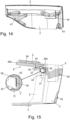
- the/each fixing pin 21 of shielding mask 16 preferably has a longitudinal blind hole 36, which ends close to the distal end of said fixing pin 21.
- the fixing pin 21 is again made of opaque polymeric material but is preferably provided with a small sector made of laser-transparent material 37, which is arranged on the bottom of the blind hole 36, or rather on the distal end of fixing pin 21, and locally takes up the entire thickness of the fixing pin 21, so as to allow the laser beam to reach the contact area 19 substantially without energy loss.
- the laser-transparent sector 37 is made of a polymeric material transparent to the wavelength of the laser beam used to realize the laser welding joint 20.
- the laser beam used to create the laser welding joint 20 reaches the contact area 19 travelling through the blind hole 36 present in the centre of the fixing pin 21. Once it has reached the bottom of the blind hole 36, the laser beam crosses the laser-transparent sector 37 of the fixing pin 21 and directly heats the rear casing 2 so as to create the laser welding joint 20.
- the laser-transparent sector 37 is furthermore made in one single piece with the fixing pin 21, or rather the shielding mask 16, via an injection moulding process of known type, such as over-injection moulding (also known as overmoulding) or bi-injection moulding.
- injection moulding process of known type, such as over-injection moulding (also known as overmoulding) or bi-injection moulding.
- the laser-transparent sector 37 is preferably made of transparent polycarbonate (PC).
- each laser-transparent sector 37 may be incorporated in the distal end of the fixing pin 21 via an injection moulding process with insert.
- the internal components of the automotive lighting device 1 include, or may include, also one or more retroreflectors, coloured lenticular filters, diffusion filters, corrective lenses, fixing bezels and/or other structural and/or support components that is/are at least partially made of opaque polymeric material, is/are arranged resting on the inner surface of rear casing 2 in at least one contact area, and is/are rigidly and non-removably fixed to the rear casing 2 via a laser welding joint realized in said contact area.
- production of the automotive lighting device 1 firstly comprises the step of producing, preferably via injection moulding, a rear casing 2 made of polymeric material opaque to visible light; and the step of producing, preferably via injection moulding, at least one lighting internal component made of polymeric material opaque to visible light (namely the reflector body 7 and/or the shielding mask 16 and/or the light-guide plate 26 and/or other components that are made of opaque polymeric material and preferably contribute to forming any one of the lighting assemblies of the lighting device).
- the casing 2 or the lighting internal component has at least one portion made of laser-transparent polymeric material which locally takes up the entire thickness of the piece.
- production of the automotive lighting device 1 comprises the step of placing said lighting internal component(s) made of opaque polymeric material (namely the reflector body 7 and/or the shielding mask 16 and/or the light-guide plate 26 and/or other components, which are made of opaque polymeric material and preferably contribute to forming any one of the lighting assemblies of the lighting device) inside the rear casing 2, resting on the inner surface of the rear casing 2 at one or more contact areas or zones; and then the step of fixing via laser welding the internal component(s) made of opaque polymeric material directly on the rear casing 2 by realizing a laser welding joint at said contact area(s).
- opaque polymeric material namely the reflector body 7 and/or the shielding mask 16 and/or the light-guide plate 26 and/or other components, which are made of opaque polymeric material and preferably contribute to forming any one of the lighting assemblies of the lighting device
- each contact area or zone between the casing 2 and the lighting internal component made of opaque polymeric material is arranged at a said portion made of laser-transparent polymeric material that locally takes up the entire thickness of the piece.
- the step of fixing via laser welding entails temporarily directing a laser beam r on the contact/ support area between the rear casing 2 and said lighting internal component made of opaque polymeric material, passing through the portion/sector made of laser-transparent polymeric material, which is adjacent/beside the contact area and it is present, on choice, on the casing 2 or on the internal component, so as to realize a laser welding joint at said contact area or zone.
- the laser beam r passes through the portion/ sector made of laser-transparent polymeric material substantially without energy loss, and reaches the opaque polymeric material at the contact area, which in turn absorbs the energy of laser beam r and heats locally up to melting temperature. More or less simultaneously the heat produced by the laser beam r is transmitted by conduction also to the polymeric material that forms the adjacent laser-transparent portion, causing the localized melting also of this second polymeric material.
- the laser beam r has a wavelength advantageously higher than 400 nm (nanometres) and more conveniently higher than 900 nm (nanometres).
- the step of fixing via laser welding preferably also comprises pressing/compressing, at the contact area, the internal component made of opaque polymeric material against the rear casing 2 and/or vice versa.
- production of automotive lighting device 1 moreover comprises the step of placing the front half-shell 3 on the mouth of the rear casing 2, and then the step of welding the front half-shell 3 to the rear casing 2 along the perimeter edge of said mouth.
- production of automotive lighting device 1 preferably also comprises the step of placing the rear casing 2 on a workpiece-carrying fixture 100, which is structured so as to accommodate and firmly retain the rear casing 2 in a given assembly position in which the mouth of the rear casing 2 advantageously faces upwards.
- the production of automotive lighting device 1 preferably entails to place the shielding mask 16 into the rear casing 2, inserting the various fixing pins 21 each inside a respective receiving seat 22 provided on the bottom of the rear casing 2; and then to direct a laser beam r onto the contact area 19, passing through the laser-transparent sector 23, so as to realize the laser welding joint 20 at said contact area 19.
- automotive lighting device 1 preferably also entails to press the/each fixing pin 21 against the bottom of the relative receiving seat 22 and/or vice versa.
- Production of the automotive lighting device 1 continues with insertion and fixing of the other components of the lighting assembly 5 and the lighting assembly 6, and ends with the welding of front half-shell 3 on the mouth of rear casing 2.
- the production method described above allows the assembly line of the automotive lighting device to be simplified and speeded up, with all advantages that this entails.
- the automatic screwdriver is one of the most delicate and problematic tools currently used in assembly lines for automotive lighting devices.
- the rear casing 2 may be provided with one or more macro-sectors made of laser-transparent material, each of which incorporates a plurality of receiving seats 12, 22 and/or 32.
- each laser-transparent macro-sector of rear casing 2 is again made of a polymeric material transparent to the wavelength of the laser beam that is used to realize the laser welding joint inside the receiving seat 12, 22 and/or 32.
- said macro-sector(s) made of laser-transparent material furthermore form the entire structure of the various receiving seats 12, 22 and/or 32.
- the rear casing 2 is advantageously provided with three laser-transparent macro-sectors 41, 42 and 43.
- the laser-transparent macro-sector 41 preferably incorporates one of the two receiving seats 12, a part of the receiving seats 22, and a part of the receiving seats 32, preferably also forming the entire structure of each of said receiving seats 12, 22, 32.
- the laser-transparent macro-sector 42 preferably incorporates a part of the receiving seats 22 and a part of the receiving seats 32, preferably also forming the entire structure of each of said receiving seats 22, 32.
- the laser-transparent macro-sectors 43 preferably incorporates one of the two receiving seats 12 and one of the receiving seats 22, preferably also forming the entire structure of each of said receiving seats 12, 22.
- the lighting assembly 6 can lack the supporting bracket 28 and the fixing pin(s) 31 are preferably made in one single piece with the light-guide plate 26, clearly again in opaque polymeric material.
- the four fixing pins 31 are arranged spaced from and beside one another, along the rear sidewall 26b of light-guide plate 26, and are made in one single piece with the light-guide plate 26 by means of an over-injection or bi-injection moulding process.
Landscapes
- Engineering & Computer Science (AREA)
- Mechanical Engineering (AREA)
- Physics & Mathematics (AREA)
- General Engineering & Computer Science (AREA)
- Electromagnetism (AREA)
- Optics & Photonics (AREA)
- Health & Medical Sciences (AREA)
- Toxicology (AREA)
- Lighting Device Outwards From Vehicle And Optical Signal (AREA)
Priority Applications (1)
| Application Number | Priority Date | Filing Date | Title |
|---|---|---|---|
| EP23199301.5A EP4528150A1 (fr) | 2023-09-25 | 2023-09-25 | Dispositif d'éclairage automobile et procédé de production associé |
Applications Claiming Priority (1)
| Application Number | Priority Date | Filing Date | Title |
|---|---|---|---|
| EP23199301.5A EP4528150A1 (fr) | 2023-09-25 | 2023-09-25 | Dispositif d'éclairage automobile et procédé de production associé |
Publications (1)
| Publication Number | Publication Date |
|---|---|
| EP4528150A1 true EP4528150A1 (fr) | 2025-03-26 |
Family
ID=88837135
Family Applications (1)
| Application Number | Title | Priority Date | Filing Date |
|---|---|---|---|
| EP23199301.5A Pending EP4528150A1 (fr) | 2023-09-25 | 2023-09-25 | Dispositif d'éclairage automobile et procédé de production associé |
Country Status (1)
| Country | Link |
|---|---|
| EP (1) | EP4528150A1 (fr) |
Citations (6)
| Publication number | Priority date | Publication date | Assignee | Title |
|---|---|---|---|---|
| US20110317443A1 (en) * | 2010-06-24 | 2011-12-29 | Kazuaki Hokoda | Vehicle lighting fitting and method for manufacturing vehicle lighting fitting |
| JP2012187897A (ja) * | 2011-03-14 | 2012-10-04 | Stanley Electric Co Ltd | 樹脂部品の製造方法及び樹脂部品同士の固定構造 |
| CN207702382U (zh) * | 2017-04-26 | 2018-08-07 | 上海小糸车灯有限公司 | 一种用于车灯的光导安装结构 |
| DE102018105567A1 (de) * | 2018-03-12 | 2019-09-12 | HELLA GmbH & Co. KGaA | Beleuchtungsvorrichtung für ein Kraftfahrzeug sowie Verfahren zu ihrer Herstellung |
| US20220107066A1 (en) * | 2020-10-02 | 2022-04-07 | Koito Manufacturing Co., Ltd. | Lamp unit |
| EP4006410A1 (fr) * | 2020-11-25 | 2022-06-01 | Marelli Automotive Lighting Italy S.p.A. | Dispositif d'éclairage et/ou de signalisation automobile et son procédé d'assemblage |
-
2023
- 2023-09-25 EP EP23199301.5A patent/EP4528150A1/fr active Pending
Patent Citations (6)
| Publication number | Priority date | Publication date | Assignee | Title |
|---|---|---|---|---|
| US20110317443A1 (en) * | 2010-06-24 | 2011-12-29 | Kazuaki Hokoda | Vehicle lighting fitting and method for manufacturing vehicle lighting fitting |
| JP2012187897A (ja) * | 2011-03-14 | 2012-10-04 | Stanley Electric Co Ltd | 樹脂部品の製造方法及び樹脂部品同士の固定構造 |
| CN207702382U (zh) * | 2017-04-26 | 2018-08-07 | 上海小糸车灯有限公司 | 一种用于车灯的光导安装结构 |
| DE102018105567A1 (de) * | 2018-03-12 | 2019-09-12 | HELLA GmbH & Co. KGaA | Beleuchtungsvorrichtung für ein Kraftfahrzeug sowie Verfahren zu ihrer Herstellung |
| US20220107066A1 (en) * | 2020-10-02 | 2022-04-07 | Koito Manufacturing Co., Ltd. | Lamp unit |
| EP4006410A1 (fr) * | 2020-11-25 | 2022-06-01 | Marelli Automotive Lighting Italy S.p.A. | Dispositif d'éclairage et/ou de signalisation automobile et son procédé d'assemblage |
Similar Documents
| Publication | Publication Date | Title |
|---|---|---|
| EP2548769B1 (fr) | Feu arrière automatique | |
| US7815354B2 (en) | Vehicle lamp housing with transparent cover welded thereon, and method | |
| US11649939B2 (en) | Automotive lighting and/or signaling device and assembly method thereof | |
| CN104943159B (zh) | 汽车灯的制造方法以及相应的汽车灯 | |
| US20120033408A1 (en) | Design panel and method for producing the same | |
| JP7146956B2 (ja) | 自動車投光装置用照明装置 | |
| JP5514496B2 (ja) | エアバッグカバーを、溶接用スタッドを備えた発射通路と溶接するための装置、および、発射通路を備えたエアバッグカバーの製造方法 | |
| EP3463980B1 (fr) | Ensemble lampe pour véhicule | |
| EP3869092A1 (fr) | Procédé de fabrication de réflecteur rotatif et réflecteur rotatif | |
| US7287877B2 (en) | Vehicular lighting device and beam welding method | |
| US12202181B2 (en) | Method for injection molding a light module for a lighting device of a motor vehicle | |
| JP2026076351A (ja) | 外部装飾要素を備える自動車用照明及び/または信号装置及び関連する組み立て方法 | |
| CN216814034U (zh) | 用于车辆的贯穿灯和具有它的车辆 | |
| CN109664020B (zh) | 车灯的同步激光焊接设备和车灯的同步激光焊接方法 | |
| US20040170847A1 (en) | Method of realizing an optical function on a component of a motor vehicle indicating or lighting device | |
| EP3297869B1 (fr) | Dispositif de conducteur lumineux doté d'un couvercle amélioré | |
| EP4527593A1 (fr) | Unité d'éclairage automobile et procédé de production associé | |
| EP4296564B1 (fr) | Feu automobile | |
| EP4527594A1 (fr) | Procédé d'assemblage d'une unité d'éclairage automobile et machine mettant en oeuvre ledit procédé | |
| US20250102129A1 (en) | Assembly Method of an Automotive Lighting Unit and Machine Implementing Such Method | |
| EP4527596A1 (fr) | Procédé d'assemblage d'une unité d'éclairage automobile et machine mettant en oeuvre ledit procédé | |
| EP4527595A1 (fr) | Procédé d'assemblage d'une unité d'éclairage automobile et machine mettant en oeuvre un tel procédé | |
| EP4612017A1 (fr) | Dispositif d'éclairage pour un dispositif de rétroviseur d'un véhicule | |
| KR101515751B1 (ko) | 차량용 휠 휀더 사이드램프 | |
| US6523983B2 (en) | Automotive lamp closeout and method of constructing same |
Legal Events
| Date | Code | Title | Description |
|---|---|---|---|
| PUAI | Public reference made under article 153(3) epc to a published international application that has entered the european phase |
Free format text: ORIGINAL CODE: 0009012 |
|
| STAA | Information on the status of an ep patent application or granted ep patent |
Free format text: STATUS: THE APPLICATION HAS BEEN PUBLISHED |
|
| AK | Designated contracting states |
Kind code of ref document: A1 Designated state(s): AL AT BE BG CH CY CZ DE DK EE ES FI FR GB GR HR HU IE IS IT LI LT LU LV MC ME MK MT NL NO PL PT RO RS SE SI SK SM TR |
|
| STAA | Information on the status of an ep patent application or granted ep patent |
Free format text: STATUS: REQUEST FOR EXAMINATION WAS MADE |
|
| 17P | Request for examination filed |
Effective date: 20250925 |