EP1837868A2 - Procédé d'enregistrement sur disque optique réinscriptible et appareil de commande du disque optique - Google Patents
Procédé d'enregistrement sur disque optique réinscriptible et appareil de commande du disque optique Download PDFInfo
- Publication number
- EP1837868A2 EP1837868A2 EP07005497A EP07005497A EP1837868A2 EP 1837868 A2 EP1837868 A2 EP 1837868A2 EP 07005497 A EP07005497 A EP 07005497A EP 07005497 A EP07005497 A EP 07005497A EP 1837868 A2 EP1837868 A2 EP 1837868A2
- Authority
- EP
- European Patent Office
- Prior art keywords
- control data
- record
- recording
- optical disc
- zone
- Prior art date
- Legal status (The legal status is an assumption and is not a legal conclusion. Google has not performed a legal analysis and makes no representation as to the accuracy of the status listed.)
- Withdrawn
Links
Images


Classifications
-
- G—PHYSICS
- G11—INFORMATION STORAGE
- G11B—INFORMATION STORAGE BASED ON RELATIVE MOVEMENT BETWEEN RECORD CARRIER AND TRANSDUCER
- G11B7/00—Recording or reproducing by optical means, e.g. recording using a thermal beam of optical radiation by modifying optical properties or the physical structure, reproducing using an optical beam at lower power by sensing optical properties; Record carriers therefor
- G11B7/007—Arrangement of the information on the record carrier, e.g. form of tracks, actual track shape, e.g. wobbled, or cross-section, e.g. v-shaped; Sequential information structures, e.g. sectoring or header formats within a track
-
- G—PHYSICS
- G11—INFORMATION STORAGE
- G11B—INFORMATION STORAGE BASED ON RELATIVE MOVEMENT BETWEEN RECORD CARRIER AND TRANSDUCER
- G11B20/00—Signal processing not specific to the method of recording or reproducing; Circuits therefor
- G11B20/10—Digital recording or reproducing
- G11B20/12—Formatting, e.g. arrangement of data block or words on the record carriers
- G11B20/1217—Formatting, e.g. arrangement of data block or words on the record carriers on discs
-
- G—PHYSICS
- G11—INFORMATION STORAGE
- G11B—INFORMATION STORAGE BASED ON RELATIVE MOVEMENT BETWEEN RECORD CARRIER AND TRANSDUCER
- G11B20/00—Signal processing not specific to the method of recording or reproducing; Circuits therefor
- G11B20/10—Digital recording or reproducing
-
- G—PHYSICS
- G11—INFORMATION STORAGE
- G11B—INFORMATION STORAGE BASED ON RELATIVE MOVEMENT BETWEEN RECORD CARRIER AND TRANSDUCER
- G11B20/00—Signal processing not specific to the method of recording or reproducing; Circuits therefor
- G11B20/10—Digital recording or reproducing
- G11B20/12—Formatting, e.g. arrangement of data block or words on the record carriers
-
- G—PHYSICS
- G11—INFORMATION STORAGE
- G11B—INFORMATION STORAGE BASED ON RELATIVE MOVEMENT BETWEEN RECORD CARRIER AND TRANSDUCER
- G11B20/00—Signal processing not specific to the method of recording or reproducing; Circuits therefor
- G11B20/10—Digital recording or reproducing
- G11B20/18—Error detection or correction; Testing, e.g. of drop-outs
- G11B20/1803—Error detection or correction; Testing, e.g. of drop-outs by redundancy in data representation
-
- G—PHYSICS
- G11—INFORMATION STORAGE
- G11B—INFORMATION STORAGE BASED ON RELATIVE MOVEMENT BETWEEN RECORD CARRIER AND TRANSDUCER
- G11B27/00—Editing; Indexing; Addressing; Timing or synchronising; Monitoring; Measuring tape travel
- G11B27/10—Indexing; Addressing; Timing or synchronising; Measuring tape travel
- G11B27/19—Indexing; Addressing; Timing or synchronising; Measuring tape travel by using information detectable on the record carrier
- G11B27/24—Indexing; Addressing; Timing or synchronising; Measuring tape travel by using information detectable on the record carrier by sensing features on the record carrier other than the transducing track ; sensing signals or marks recorded by another method than the main recording
-
- G—PHYSICS
- G11—INFORMATION STORAGE
- G11B—INFORMATION STORAGE BASED ON RELATIVE MOVEMENT BETWEEN RECORD CARRIER AND TRANSDUCER
- G11B27/00—Editing; Indexing; Addressing; Timing or synchronising; Monitoring; Measuring tape travel
- G11B27/10—Indexing; Addressing; Timing or synchronising; Measuring tape travel
- G11B27/19—Indexing; Addressing; Timing or synchronising; Measuring tape travel by using information detectable on the record carrier
- G11B27/28—Indexing; Addressing; Timing or synchronising; Measuring tape travel by using information detectable on the record carrier by using information signals recorded by the same method as the main recording
- G11B27/32—Indexing; Addressing; Timing or synchronising; Measuring tape travel by using information detectable on the record carrier by using information signals recorded by the same method as the main recording on separate auxiliary tracks of the same or an auxiliary record carrier
- G11B27/327—Table of contents
- G11B27/329—Table of contents on a disc [VTOC]
-
- G—PHYSICS
- G11—INFORMATION STORAGE
- G11B—INFORMATION STORAGE BASED ON RELATIVE MOVEMENT BETWEEN RECORD CARRIER AND TRANSDUCER
- G11B7/00—Recording or reproducing by optical means, e.g. recording using a thermal beam of optical radiation by modifying optical properties or the physical structure, reproducing using an optical beam at lower power by sensing optical properties; Record carriers therefor
- G11B7/004—Recording, reproducing or erasing methods; Read, write or erase circuits therefor
- G11B7/0045—Recording
-
- G—PHYSICS
- G11—INFORMATION STORAGE
- G11B—INFORMATION STORAGE BASED ON RELATIVE MOVEMENT BETWEEN RECORD CARRIER AND TRANSDUCER
- G11B7/00—Recording or reproducing by optical means, e.g. recording using a thermal beam of optical radiation by modifying optical properties or the physical structure, reproducing using an optical beam at lower power by sensing optical properties; Record carriers therefor
- G11B7/004—Recording, reproducing or erasing methods; Read, write or erase circuits therefor
- G11B7/006—Overwriting
-
- G—PHYSICS
- G11—INFORMATION STORAGE
- G11B—INFORMATION STORAGE BASED ON RELATIVE MOVEMENT BETWEEN RECORD CARRIER AND TRANSDUCER
- G11B7/00—Recording or reproducing by optical means, e.g. recording using a thermal beam of optical radiation by modifying optical properties or the physical structure, reproducing using an optical beam at lower power by sensing optical properties; Record carriers therefor
- G11B7/007—Arrangement of the information on the record carrier, e.g. form of tracks, actual track shape, e.g. wobbled, or cross-section, e.g. v-shaped; Sequential information structures, e.g. sectoring or header formats within a track
- G11B7/00736—Auxiliary data, e.g. lead-in, lead-out, Power Calibration Area [PCA], Burst Cutting Area [BCA], control information
-
- G—PHYSICS
- G11—INFORMATION STORAGE
- G11B—INFORMATION STORAGE BASED ON RELATIVE MOVEMENT BETWEEN RECORD CARRIER AND TRANSDUCER
- G11B7/00—Recording or reproducing by optical means, e.g. recording using a thermal beam of optical radiation by modifying optical properties or the physical structure, reproducing using an optical beam at lower power by sensing optical properties; Record carriers therefor
- G11B7/12—Heads, e.g. forming of the optical beam spot or modulation of the optical beam
- G11B7/125—Optical beam sources therefor, e.g. laser control circuitry specially adapted for optical storage devices; Modulators, e.g. means for controlling the size or intensity of optical spots or optical traces
- G11B7/126—Circuits, methods or arrangements for laser control or stabilisation
- G11B7/1267—Power calibration
-
- G—PHYSICS
- G11—INFORMATION STORAGE
- G11B—INFORMATION STORAGE BASED ON RELATIVE MOVEMENT BETWEEN RECORD CARRIER AND TRANSDUCER
- G11B20/00—Signal processing not specific to the method of recording or reproducing; Circuits therefor
- G11B20/10—Digital recording or reproducing
- G11B2020/10861—Finalising a record carrier after a recording operation, e.g. to ensure compatibility with a ROM medium
-
- G—PHYSICS
- G11—INFORMATION STORAGE
- G11B—INFORMATION STORAGE BASED ON RELATIVE MOVEMENT BETWEEN RECORD CARRIER AND TRANSDUCER
- G11B20/00—Signal processing not specific to the method of recording or reproducing; Circuits therefor
- G11B20/10—Digital recording or reproducing
- G11B20/12—Formatting, e.g. arrangement of data block or words on the record carriers
- G11B20/1217—Formatting, e.g. arrangement of data block or words on the record carriers on discs
- G11B2020/1218—Formatting, e.g. arrangement of data block or words on the record carriers on discs wherein the formatting concerns a specific area of the disc
- G11B2020/122—Burst cutting area [BCA]
-
- G—PHYSICS
- G11—INFORMATION STORAGE
- G11B—INFORMATION STORAGE BASED ON RELATIVE MOVEMENT BETWEEN RECORD CARRIER AND TRANSDUCER
- G11B20/00—Signal processing not specific to the method of recording or reproducing; Circuits therefor
- G11B20/10—Digital recording or reproducing
- G11B20/12—Formatting, e.g. arrangement of data block or words on the record carriers
- G11B20/1217—Formatting, e.g. arrangement of data block or words on the record carriers on discs
- G11B2020/1218—Formatting, e.g. arrangement of data block or words on the record carriers on discs wherein the formatting concerns a specific area of the disc
- G11B2020/1222—ECC block, i.e. a block of error correction encoded symbols which includes all parity data needed for decoding
-
- G—PHYSICS
- G11—INFORMATION STORAGE
- G11B—INFORMATION STORAGE BASED ON RELATIVE MOVEMENT BETWEEN RECORD CARRIER AND TRANSDUCER
- G11B20/00—Signal processing not specific to the method of recording or reproducing; Circuits therefor
- G11B20/10—Digital recording or reproducing
- G11B20/12—Formatting, e.g. arrangement of data block or words on the record carriers
- G11B2020/1264—Formatting, e.g. arrangement of data block or words on the record carriers wherein the formatting concerns a specific kind of data
- G11B2020/1265—Control data, system data or management information, i.e. data used to access or process user data
- G11B2020/1267—Address data
-
- G—PHYSICS
- G11—INFORMATION STORAGE
- G11B—INFORMATION STORAGE BASED ON RELATIVE MOVEMENT BETWEEN RECORD CARRIER AND TRANSDUCER
- G11B20/00—Signal processing not specific to the method of recording or reproducing; Circuits therefor
- G11B20/10—Digital recording or reproducing
- G11B20/12—Formatting, e.g. arrangement of data block or words on the record carriers
- G11B2020/1264—Formatting, e.g. arrangement of data block or words on the record carriers wherein the formatting concerns a specific kind of data
- G11B2020/1265—Control data, system data or management information, i.e. data used to access or process user data
- G11B2020/1275—Calibration data, e.g. specific training patterns for adjusting equalizer settings or other recording or playback parameters
-
- G—PHYSICS
- G11—INFORMATION STORAGE
- G11B—INFORMATION STORAGE BASED ON RELATIVE MOVEMENT BETWEEN RECORD CARRIER AND TRANSDUCER
- G11B20/00—Signal processing not specific to the method of recording or reproducing; Circuits therefor
- G11B20/10—Digital recording or reproducing
- G11B20/12—Formatting, e.g. arrangement of data block or words on the record carriers
- G11B2020/1264—Formatting, e.g. arrangement of data block or words on the record carriers wherein the formatting concerns a specific kind of data
- G11B2020/1265—Control data, system data or management information, i.e. data used to access or process user data
- G11B2020/1277—Control data, system data or management information, i.e. data used to access or process user data for managing gaps between two recordings, e.g. control data in linking areas, run-in or run-out fields, guard or buffer zones
-
- G—PHYSICS
- G11—INFORMATION STORAGE
- G11B—INFORMATION STORAGE BASED ON RELATIVE MOVEMENT BETWEEN RECORD CARRIER AND TRANSDUCER
- G11B2220/00—Record carriers by type
- G11B2220/20—Disc-shaped record carriers
- G11B2220/21—Disc-shaped record carriers characterised in that the disc is of read-only, rewritable, or recordable type
- G11B2220/215—Recordable discs
- G11B2220/216—Rewritable discs
Definitions
- the present invention relates to a recording method on a rewritable optical disc that recording and reproducing operations of a data are performed by use of a fine light spot, and an apparatus for driving the same.
- CD-R Compact Disc-Recordable
- DVD-R Digital Versatile Disc-Recordable
- CD-RW Compact Disc-ReWritable
- DVD-RW DVD-Rewritable
- spiral groove tracks for tracking are formed on an optical disc substrate, and a multi-layer record layer formed of phase change material is formed thereon.
- a laser beam of high power is focused onto this record layer, and the crystal structure of the phase change material is partially changed, to form record pits.
- the data is recorded as the record pits.
- the disc After the data is recorded, the disc has the same data format as a ROM medium in which the embossed data pit sequences are formed, and a servo signal of a substantially same property can be obtained.
- the driving apparatus dedicated to the reproduction there is a merit that it can be easily reproduced even the driving apparatus dedicated to the reproduction.
- the recorded data is erased by emitting a laser beam whose power is slightly lower than a power when a data is recorded to return the crystal structure of the phase change material to the original state.
- the laser beam is generated by adding a record power of a new data to be next recorded to a record power necessary for the erasing operation and is emitted to the optical disc.
- the already-recorded data is erased, and the new data is recorded, thereby the rewrite of the data becomes possible.
- the change in the crystal structure of the phase change material is used when the data is recorded.
- the repetition of the rewrite gradually brings about the deterioration in the property of a record signal.
- this has a merit that the actual number of times of the repetition between hundred of times and thousands of times can be cheaply attained.
- Fig. 2 shows a configuration example of a record area of the rewritable optical disc.
- the record area of an optical disc 1 is divided into an inner circumference control data record area 3, a user data recording area 4 and an outer circumference control data record area 5 in a radial direction.
- the user data is recorded in the user data recording area 4, and its control data and the like are recorded in the inner circumference control data record area 3 and the outer circumference control data record area 5.
- an ending process is performed such that the reproduction is possible even in the driving apparatus dedicated to the reproduction.
- the ending process record pits in a predetermined width or more in the radial direction are formed in the inner circumference control data record area 3 close to the user data recording area 4. This is because in the driving apparatus dedicated to the reproduction, only the area where the record pits are formed is accessible in many cases, and when a search operation is performed over the user data recording area, a position address is reproduced based on the record pits formed in the ending process so that an access control is possible.
- the record pits for the ending process as mentioned above are formed over the width of several hundred ⁇ m in the radial direction.
- a control data record zone to record control data indicating the record state of the optical disc 1 is typically set in the inner circumference control data record area 3.
- This control data is a data essential for the recording/reproducing operation in the driving apparatus, such as a data record position inside a user data area, a parameter data for a servo control, and a record power data.
- its reliability is required to be reserved higher than that of the user data.
- the rewritable optical disc has a possibility that the control data is rewritten each time the user data is rewritten. Therefore, the rewriting frequency of the control data tends to be higher than that of the user data.
- the control data record zone is divided into a plurality of divisions, in order to ensure the reliability when this control data is recorded.
- the control data is repeatedly recorded in one division, and when the increase in the number of times of the rewrite causes the signal property to be deteriorated, a next division is newly used to record the control data.
- the recording of the control data through the employment of the method of changing the record division when the property is deteriorated as mentioned above, it is possible to perform the rewriting operation more than the limited number of times of the rewrite of the recording layer.
- the record property is naturally different depending on the presence or absence of the use of the division, and the used division whose property is deteriorated has a possibility that it is also difficult to reproduce a position address from a recorded signal.
- the control data record zone cannot be set for a portion, which is close to the user data recording area and requires the ending process. Therefore, there is a limit that it must be set for a portion on an inner circumferential side away from the user data recording area even inside an inner circumference control data record area. Therefore, when the recording of the user data and the recording of the control data are performed frequently and alternately, this method has a defect that the loss of the access time caused by the long distance is generated in many times.
- the using method similar to a recordable optical disc to which data can be written only one time is defined.
- the new control data is additionally recorded to the non-recorded area of the control data record zone, when the recorded user data is increased by a predetermined record capacity. It is recorded in each portion inside the control data record zone, basically only one time, and the number of times of the recording operation is limited in accordance with the zone capacity.
- this zone is erased entirely and collectively, and it is returned to the non-recorded area and then recorded.
- the additionally recordable portion of the user data area is basically limited to a portion next to the already-recorded area.
- the state of the user data area can be recognized to some degree by reproducing the previously old control data.
- JP- P2000-076786A discloses a disc still image recording method, in which a still image is recorded on a disc in which the number of times of a recording operation is limited.
- the disc is provided with a still image record area where the still image is recorded; a plurality of record position data sectors in which record position data indicating the position of the still image on the disc is recorded; and a pointer sector where the data to specify the record position data sector is recorded in which a final record position data is written.
- the still image is recorded, the still image is recorded in a particular position of the still image record area in accordance with the final record position data of the record position data sector specified by the pointer sector.
- the record position data of the still image and the number of the recordings in the record position data sector are update-recorded in the same record position data sector or a different record position data sector.
- the pointer sector is update-recorded in the data to specify this record position data sector.
- JP-P2009-103078A discloses a data record medium, which has a reproduction data area and a control data area, and which the control data is recorded as a PEP (Phase Encoded Part) signal.
- a reproduction data to be reproduced is recorded in the reproduction data area.
- the control data including a reproduction control data necessary when at least the reproduction data is reproduced is equally CAV (Constant Angular Velocity) recorded in a plurality of tracks with an amount corresponding to one rotation of a track as one unit.
- the data of the data area recorded as the PEP signal is divided into a plurality of error correction units, and an error correction code is recorded in the data area for each error correction unit.
- a BCA Breastt Cutting Area
- JP-P2005-327385A discloses a method of recording data on an optical disc.
- An optical disc medium contains a data area in which a user data is recorded; a first system area inside the data area; and a second system area outside the data area.
- the first system area includes a first learning area to set an optimal condition in the recording operation in the data area; and a management data record area to manage a data in the recording operation of the user data in the data area.
- the second system area includes a protection area to protect the user data therein; and a second learning area to set an optimal condition in the recording operation in the data area outside the protection area.
- This management data record area includes an area for a data indicating the use state of the protection area to be recorded.
- the optimal condition in the recording is determined in the second learning area and the protection area.
- a data indicating a using method of the protection area is recorded in the area to record the data indicating the using method of the protection area.
- a recording method on a rewritable optical disc is achieved by setting a control data recording zone in which a control data is recorded, to a portion of the optical disc which is close to a user data recording area in an inner circumference control data record area; wherein a spiral recordable track of the optical disc is divided into the inner circumference control data record area, the user data recording area, an outer control data record area from an inner circumference side; wherein the control data indicates record states of the inner circumference control data record area, the user data recording area, and the outer control data record area in the optical disc; by recording a new control data on one of a plurality of record divisions contained in the control data recording zone; and by setting a planned record division for the control data to be next recorded after the control data is recorded in the one record division.
- the set control data recording zone may include an ending process record area portion in which record pits have been formed until an ending process.
- the record division may include a plurality of ECC blocks, each of the plurality of ECC blocks being a minimum unit when a data is recorded on the optical disc.
- the recording is achieved by recording the control data to each of the plurality of ECC blocks of the optical disc.
- control data may have a count value in which an order for a data to be recorded in the record division is written.
- control data may further have a data indicating a defect detected in the record in the record division.
- the setting a planned record division is achieved by setting the record division on an outer circumferential side by one record division to the planned record division each time the control data has been recorded in the record division.
- the setting a planned record division may be achieved by setting the record division on an innermost circumferential side to the planned record division when the control data has been recorded in the record division on an outermost circumferential side.
- the control data recording zone may be used circulatedly.
- the recording method may be achieved by further setting a control data replica zone in which a replica of the control data is recorded on an inner circumferential side of the control data recording zone; and recording a latest the control data and a position data indicating the record division in which the latest control data has been recorded, as a replica control data in the control data replica zone.
- control data replica zone contains a plurality of ECC blocks.
- the recording a latest the control data may be achieved by recording the replica control data to one of the plurality of ECC blocks in the control data replica zone.
- control data replica zone may include the ECC blocks of a number which is less than 1/10 of a number of the record divisions in the control data recording zone.
- the recording a latest the control data may be achieved by recording the replica control data to the control data replica zone when the optical disc is ejected.
- the recording a latest the control data may be achieved by circulatedly using the plurality of ECC blocks in the control data replica zone.
- an optical disc drive apparatus includes an optical head configured to irradiate a laser beam to an optical disc to record a data, and to reproduce a reproduction signal of the recorded data based on a reflection beam reflected by the optical disc; wherein in the optical disc, a recordable spiral track is divided into an inner circumference control data record area, a user data recording area, and an outer circumference control data record area from an inner circumferential side; a signal detecting section configured to extract a signal indicating an address of the optical disc based on the reproduction signal; an address determining section configured to specify a position in the optical disc based on the signal indicating the address; and a control data recording section configured to record a control data indicating a record state of the optical disc in one of a plurality of record divisions of a control data recording zone to have been set to a portion of the optical disc close to the user data recording area in the inner circumference control data record area specified by the address determining section, and to set a planed record division where the control data
- control data recording section may circulatedly assign each of the plurality of record divisions as the planed record division.
- control data recording section may record a latest one of the control data and a data indicating a position of the record division where the latest control data has been recorded in a control data replica zone provided on a further inner circumferential side than the control data recording zone as a replica control data.
- control data replica zone may include a plurality of ECC blocks less than a number of record divisions contained in the control data recording zone.
- the control data recording section may record the replica control data to one of the plurality of ECC blocks contained in the control data replica zone.
- control data recording section ay record the replica control data when the optical disc is ejected.
- control data recording section may record the replica control data by using the plurality of ECC blocks contained in the control data replica zone circulatedly.
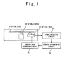
- Fig. 1 shows the configuration of the driving apparatus according to the present invention.
- the driving apparatus contains a spindle 30, an optical head 31, a signal detecting circuit 34, an address determining circuit 35 and a control data recording circuit 36.
- a portion of a rewritable optical disc 1 where a control data is recorded is described, and the description of the others are omitted.
- the spindle 30 rotates and drives the optical disc 1.
- the optical head 31 reproduces a reproduction signal corresponding to a data recorded in the optical disc 1 from a reflection light when an emitted laser beam is reflected by the rotating optical disc 1. Also, the optical head 31 emits the strong laser beam, and the data is recorded in the optical disc 1 or it is erased.
- the reproduction signal reproduced by the optical head 31 is supplied to the signal detecting circuit 34.
- the signal detecting circuit 34 extracts a signal indicative of an address of the optical disc 1 from the reproduction signal, and sends to the address determining circuit 35.
- the address determining circuit 35 specifies one of various areas and one of zones in accordance with the signal indicative of the address of the optical disc 1.
- the control data recording circuit 36 records the control data necessary for the specified control data recording zone, the specified control data replica zone and the like on the optical disc 1.
- Fig. 2 shows the configuration of the record area of the optical disc 1.
- a spiral recording track 2 is formed on the record surface of the optical disc 1.
- the lower portion of Fig. 2 shows the section of a portion AA' of the optical disc 1 for the recording track 2.
- the laser beam emitted from the optical head 31 generates a light focused spot on a record layer 6, in which the data is recorded, through a transparent layer 7 of the optical disc 1.
- the record layer 6 for example, a multi-layer film is used in which a film of the phase change material such as GeSbTe compound is sandwiched with dielectric protection layers of SiN.
- a mold shape formed by injection molding is used in which grooves for the recording track are formed on a polycarbonate substrate.
- the recording track 2 is divided into the inner circumference control data record area 3, the user data recording area 4 and the outer circumference control data record area 5 from the inner circumference side. Each area is further divided into such zones as shown in Fig. 3.
- the inner circumference control data record area 3 contains a reproduction data record zone 11, a control data record zone 12, a control data replica zone 13 and a test record zone 14, from the side of the user data recording area 4 (the outer circumference side).
- the reproduction data recording zone 11 and the control data recording zone 12 are contained in an ending process portion 8.
- the ending process portion 8 is a portion where record pits are formed through the ending process in order to reserve the compatibility with the driving apparatus dedicated to the reproduction.
- the reproduction data recording zone 11 is an area that is read-accessed by a driving apparatus dedicated to reproduction, and a data to know the record state of the user data recording area 4 is recorded.
- the reproduction data recording zone 11 may be sufficient if a recording apparatus can record a small amount of data as the ending process after a user data recording process. Thus, it is sufficient that a small area is reserved.
- the control data recording zone 12 and the control data replica zone 13 are areas where a control data is recorded when the user data is recorded in the user data recording area 4.
- the test recording zone 14 is an area used when the driving apparatus carries out a trial recording operation and searches an optimal record condition such as a record power.
- the outer circumference control data record area 5 contains a guard zone 17 and a test recording zone 16, from the side of the user data recording area 4 (the inner circumference side).
- the guard zone 17 is reserved to additionally form the record pits after the recording operation of the user data is ended, in order that a driving apparatus dedicated to reproduction can carry out the control even if it overruns the user data recording area 4.
- the test recording zone 16 is an area used when the driving apparatus carries out a trial recording operation and searches the optimal record condition such as the record power, similarly to the test recording zone 14 in the inner circumference control data record area 3.
- the area configuration of the control data recording zone 12 and the control data replica zone 13 will be described below.
- the record on the optical disc 1 and reproduction from it are usually performed in units of ECC blocks which are minimum units, and in which an error correction code is added to an original data.
- the effective data amount of this ECC block is assumed to be 32 Kbytes in a DVD standard and 64 Kbytes in an HD DVD standard.
- the ECC block has a capacity enough to store the control data.
- the recording operations in the control data recording zone 12 and the control data replica zone 13 are performed in units of ECC blocks.
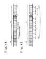
- Figs. 4A and 4B show the area configuration of the control data recording zone 12 and the control data replica zone 13 in units of ECC blocks, respectively.
- the control data replica zone 13 contains 7 ECC blocks 20
- the control data recording zone 12 contains about 100 record divisions 21, each of which is composed of 4 ECC blocks 20.
- the control data of the same content is recorded in the record division 21 four times. That is, the control data is recorded in each ECC block 20, and the 4 ECC blocks 20 in the record division 21 hold the same content. In this way, since the same control data is recorded in the plurality of ECC blocks 20, the reliability at the time of the reproduction can be improved.
- the number of the ECC blocks 20 contained in the record division 21 is determined under consideration of the reliability of the record medium and a time necessary for the recording operation.
- a proper value is between several blocks and 8 blocks.
- the 4 blocks is exemplified.
- FIG. 4B An order when the control data is recorded in the record division 21 in the control data recording zone 12 is circulated, as shown in Fig. 4B.
- the control data is recorded in an order starting from a record division 21-1 on the inner circumferential side.
- the record divisions 21 on the outer circumferential side are sequentially used, one by one, such as record divisions 21-2, 21-3, ....
- the record division 21 in which the control data is recorded arrives at the record division 21-n on the outermost circumferential side, at the time of the n-th recording operation.
- the next (n+1)-th control data is also recorded in the record division 21-1 on the innermost circumferential side.
- the record divisions 21 are circulatedly used from the inner circumferential side to the outer circumferential side.
- the number of times of the recording operation of the control data is never limited by the capacity of the control data recording zone 12.
- the number of times of the rewriting operation is substantially uniform, and the deterioration in the record property through the repetitive recording operation can be prevented from being locally generated.
- the signal reproduction is performed substantially in the entire of the control data recording zone 12 until the deterioration in the record property.
- the control data recording zone 12 can be set for an area which is located close to the user data recording area 4 and on which the ending process must be performed. Therefore, an access time when the user data recording area 4 and the control data recording zone 12 are alternately accessed is made shorter, which can reduce the recording operation time of the user data.
- the control data can be recorded in the area requiring the ending process.
- the number of record divisions 21 contained in the control data recording zone 12 may be a approximate number by which the area width requiring the ending process can be reserved.
- the newest control data is recorded in one of the non-recorded record divisions 21 in the ending process.
- the control data are recorded in the adjacent record divisions 21 one after another.
- all of the record divisions 21 in the control data recording zone 12 become the already-recorded state in a relatively short time.
- the number of non-recorded record divisions 21 in which the control data must be recorded at the time of the ending process is made smaller. That is, the time of the ending process can be reduced.
- the position of the defective record division 21-i may be contained in the control data and recorded. In this case, when the control data are circulatedly recorded in the record division 21-i of the same position, a defect control such as skipping of the division can be performed.
- the control data replica zone 13 is provided on the inner circumferential side of the control data recording zone 12, as shown in Figs. 4A and 4B.
- the replica of the newest control data is recorded together with the position data of the record division where the newest control data is recorded.
- the control data replica zone 13 is provided to increase the speed of the retrieval of the newest control data.
- the control data includes a counter value that is counted up each time it is updated to the new data.
- the retrieval of the newest control data in the control data recording zone 12 can be attained by finding out the greatest counter value. However, the retrieval from the entire of record divisions 21 composed of about 100 divisions requires a certain reasonable time.
- the replica of the newest control data together with the position data of the record division 21 where the newest control data is recorded is recorded in the control data replica zone 13.
- this control data replica zone 13 is firstly reproduced, the newest control data and its record position can be easily known.
- control data to be recorded in the control data replica zone 13 is recorded only in one of the ECC blocks 20.
- the control data replica zone 13 includes the plurality of ECC blocks 20.
- the control data is recorded in the plurality of ECC blocks 20, a method is employed which circulatedly repeats the recording operation from the inner circumferential side to the outer circumferential side one by one, similarly to the control data recording zone 12.
- the number of the blocks of the ECC blocks 20 is made smaller than the number of the record divisions 21, and it is set such that the retrieval time is reduced. As shown in Figs.
- the number of ECC blocks 20 in the control data replica zone 13 is 7 while the number of record divisions 21 is about 100.
- the number of ECC blocks is set to be 1/10 or less of the number of the record divisions 21.
- Figs. 5A to 5C are diagrams showing the change in record state of the optical disc where the user data is recorded by the driving apparatus.
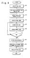
- Fig. 6 is a flowchart showing the operation of the driving apparatus.
- the driving apparatus reads the replica control data recorded in the control data replica zone 13 of the optical disc 1 (Step S12). If it is already recorded in the optical disc 1, the driving apparatus reads all of the replica control data recorded in the control data replica zone 13 of the optical disc 1. Also, in case of the non-recorded optical disc 1, there is no recorded control data. Thus, an initial value is set for the control data. In that case, the use of the record division 21 on the innermost circumferential side in the control data recording zone 12 is set when the control data is recorded. In accordance with the set control data, the driving apparatus sets the position of each area to be used.
- the replica control data includes the control data and the position data of the control data recording zone 12 where the control data is recorded, and the control data includes a counter value.
- the control data replica zone 13 contains 7 ECC blocks 20, the 7 counter values are obtained.
- the replica control data having the greatest counter value among them is the newest replica control data.
- the record division 21 of the control data recorded in the control data recording zone 12 is specified (Step S19).
- the driving apparatus uses the test recording zone 14 on the inner circumferential side and carries out the optimization adjustment of the record power.
- the test recording zone 14 is used for a trial recording operation, sequentially from an area 141 on the outer circumferential side (Step S15).
- Step S16 When the record power is adjusted, the user data is recorded from the inner circumferential side of the user data recording area 4, and a record portion 401 is then formed (Step S16). In the pause of the recording of the user data, the control data is sequentially recorded even in the record division 21 of the control data recording zone 12, and an already-recorded area 121 is formed in the control data recording zone 12 (Step S18).
- Step S21-N the driving apparatus uses the test recording zone 14 on the inner circumferential side and the test recording zone 16 on the outer circumferential side, as necessary, and adjusts the record condition.
- the user data is recorded in the user data recording area 4, and a record portion 402 is formed.
- the control data is recorded in the control data recording zone 12, and a record portion 122 is formed.
- an area 142 of the test recording zone 14 and an area 162 of the test recording zone 16 become in an already-used state. In this stage, if the recording operation of the user data has been ended (Step S21-Y), the ending process is next performed.
- the target of the ending process is an ending process portion 8 on the side of the user data recording area 4 in the inner circumference control data record area 3 and an ending process portion 403 on the outer circumferential side in the portion 402 where the user data is recorded, as shown in Fig. 5C.
- the ending process portion 8 includes the reproduction data recording zone 11 and the control data recording zone 12, and a predetermined data is recorded in the non-recorded portion in this area.
- the ending process portions 8 are all in the already-recorded state through in the ending process. If there is not the non-recorded portion, the recording operation can be omitted.
- predetermined data is recorded over the width in a predetermined radius direction.
- the width of this portion may be narrower than the ending process portion 8 on the inner circumferential side in the user data recording area 4 and can be set to about 50 ⁇ m. It should be noted that when all of the user data recording areas 4 become in the already-recorded state with the user data, this ending process portion 403 is set for the guard zone 17 on the outer circumference (Step S23).
- the replica of the newest control data together with the position data indicative of the position where the newest control data is recorded is circulatedly recorded in the control data replica zone 13 (Step S25). Either of the ending process to be recorded in the non-recorded portion and the process for recording the replica control data in the control data replica zone 13 may be earlier performed.
- the already-recorded optical disc 1 can be produced even by the driving apparatus dedicated to reproduction is created, and the optical disc 1 is taken away from the driving apparatus, and the recording process is ended (Step S26).
- the user data are assumed to be continuously recorded from the inner circumferential side.
- the user data can be randomly recorded in the user data recording area 4.
- the non-recorded area portions of the area portions where the user data are discretely recorded require a process for setting all of area portions to be in the already-recorded state until the performance of the ending process.
- an updating process of the control data namely, a process for recording the new control data in the control data recording zone 12 is usually performed when the control data is changed.
- the driving apparatus can store the changed control data in a memory of the apparatus and record it on the optical disc only when the optical disc is taken away or when the power source is turned off.
- the present invention has been described by exemplifying the rewritable optical disc of the single layer.
- the control data recording zone close to the user data area on the inner circumferential side of one record layer, it is possible to apply the similar recording method and driving apparatus.
Landscapes
- Engineering & Computer Science (AREA)
- Signal Processing (AREA)
- Physics & Mathematics (AREA)
- Optics & Photonics (AREA)
- Optical Recording Or Reproduction (AREA)
- Signal Processing For Digital Recording And Reproducing (AREA)
Applications Claiming Priority (1)
| Application Number | Priority Date | Filing Date | Title |
|---|---|---|---|
| JP2006077135A JP2007257686A (ja) | 2006-03-20 | 2006-03-20 | 書き換え型光ディスク記録方法及び光ディスクドライブ装置 |
Publications (2)
| Publication Number | Publication Date |
|---|---|
| EP1837868A2 true EP1837868A2 (fr) | 2007-09-26 |
| EP1837868A3 EP1837868A3 (fr) | 2009-07-29 |
Family
ID=38197850
Family Applications (1)
| Application Number | Title | Priority Date | Filing Date |
|---|---|---|---|
| EP07005497A Withdrawn EP1837868A3 (fr) | 2006-03-20 | 2007-03-16 | Procédé d'enregistrement sur disque optique réinscriptible et appareil de commande du disque optique |
Country Status (6)
| Country | Link |
|---|---|
| US (1) | US20070230300A1 (fr) |
| EP (1) | EP1837868A3 (fr) |
| JP (1) | JP2007257686A (fr) |
| KR (1) | KR100852530B1 (fr) |
| CN (1) | CN101042913A (fr) |
| TW (1) | TW200809813A (fr) |
Families Citing this family (5)
| Publication number | Priority date | Publication date | Assignee | Title |
|---|---|---|---|---|
| JP2007157297A (ja) * | 2005-12-08 | 2007-06-21 | Nec Corp | 記録型光ディスク装置および光ディスク媒体 |
| JP2013065370A (ja) * | 2011-09-16 | 2013-04-11 | Hitachi Consumer Electronics Co Ltd | 交替領域を有する媒体及びその記録装置並びに記録方法 |
| US11335371B2 (en) * | 2016-09-30 | 2022-05-17 | Sony Semiconductor Solutions Corporation | Reproduction apparatus and reproduction method |
| CN106652152A (zh) * | 2016-10-17 | 2017-05-10 | 深圳市穗彩科技开发有限公司 | 电子摇奖系统的数据存储方法及装置 |
| JP2019164871A (ja) * | 2018-03-20 | 2019-09-26 | 株式会社東芝 | 磁気ディスク装置及び磁気ディスク装置の制御方法 |
Family Cites Families (34)
| Publication number | Priority date | Publication date | Assignee | Title |
|---|---|---|---|---|
| US5701281A (en) * | 1995-07-13 | 1997-12-23 | Nec Corporation | Optical disk device capable of recording a control parameter on unused optical disk area |
| JPH09115246A (ja) * | 1995-10-19 | 1997-05-02 | Sony Corp | 情報記録方法及び情報記録装置並びに記録媒体 |
| US5940853A (en) * | 1996-02-23 | 1999-08-17 | Matsushita Electric Industrial Co., Ltd. | Recording and reproducing apparatus enabling modification of data recorded on a non-erasable recording medium |
| JP3991369B2 (ja) * | 1996-04-11 | 2007-10-17 | 松下電器産業株式会社 | 光ディスク |
| JPH1083658A (ja) * | 1996-09-04 | 1998-03-31 | Sony Corp | 記録装置および記録媒体 |
| JPH10112166A (ja) * | 1996-10-04 | 1998-04-28 | Sony Corp | 光ディスクのファイナライゼーション方法および光ディスクのファイナライゼーション装置 |
| KR100491233B1 (ko) * | 1996-10-07 | 2005-05-25 | 마츠시타 덴끼 산교 가부시키가이샤 | 광 디스크, 광 디스크 장치 및 광 디스크 기록 방법 |
| US6163521A (en) * | 1997-04-16 | 2000-12-19 | Matsushita Electric Industrial Co., Ltd. | Disk having read-only and read-write areas |
| MY126551A (en) * | 1997-09-17 | 2006-10-31 | Matsushita Electric Industrial Co Ltd | Video data editing apparatus and computer-readable recording medium storing an editing program |
| GB2336021B (en) * | 1998-04-01 | 2000-05-03 | Ricoh Kk | Optical-disc recording device |
| WO2000019432A1 (fr) * | 1998-09-25 | 2000-04-06 | Matsushita Electric Industrial Co., Ltd. | Support d'enregistrement d'information, procede et dispositif d'enregistrement et de reproduction d'information |
| JP3478159B2 (ja) * | 1999-03-29 | 2003-12-15 | ヤマハ株式会社 | 光ディスクのディスク情報取得方法、アクセス制御方法、記録制御方法および光ディスク記録装置 |
| JP3783909B2 (ja) * | 1999-05-20 | 2006-06-07 | パイオニア株式会社 | カッティング装置、情報記録媒体、情報記録装置及び情報記録方法並びに、カッティング方法 |
| KR100611953B1 (ko) * | 1999-07-07 | 2006-08-11 | 삼성전자주식회사 | 기본 단위 속성 정보를 저장하는 기록 매체와 이 속성 정보를 이용한 데이터 판별 방법 |
| EA003197B1 (ru) * | 1999-10-20 | 2003-02-27 | Конинклейке Филипс Электроникс Н.В. | Доступный только для чтения носитель записи и устройство считывания |
| JP2001266495A (ja) * | 2000-03-24 | 2001-09-28 | Sony Corp | 光ディスク及び光ディスク駆動装置 |
| JP2002015549A (ja) * | 2000-06-26 | 2002-01-18 | Sony Corp | 記録再生装置及び記録再生方法 |
| JP4806839B2 (ja) * | 2000-07-19 | 2011-11-02 | ソニー株式会社 | 記録装置、記録方法 |
| US6628602B2 (en) * | 2000-07-27 | 2003-09-30 | Victor Company Of Japan | Optical information recording medium |
| KR100475604B1 (ko) * | 2001-03-09 | 2005-03-10 | 엘지전자 주식회사 | 재생전용 광디스크와, 그 재생전용 광디스크 장치에서의재생방법 |
| US7023775B2 (en) * | 2001-03-22 | 2006-04-04 | Matsushita Electric Industrial Co., Ltd. | Recording apparatus and method, and reproduction apparatus and method for recording data to or reproducing data from a write once type information recording medium, and write once type information recording medium |
| RU2297678C2 (ru) * | 2001-04-24 | 2007-04-20 | Конинклейке Филипс Электроникс Н.В. | Устройство и способ для записи информации |
| KR100716962B1 (ko) * | 2001-09-29 | 2007-05-10 | 삼성전자주식회사 | 광디스크 |
| JP3797191B2 (ja) * | 2001-10-25 | 2006-07-12 | 株式会社日立製作所 | 情報記録装置 |
| JP2004030860A (ja) | 2002-04-30 | 2004-01-29 | Pioneer Electronic Corp | 記録ディスク及び記録情報再生装置並びに記録情報再生方法 |
| EP1506545B1 (fr) * | 2002-05-20 | 2008-05-28 | Samsung Electronics Co., Ltd. | Disque optique et procede d'enregistrement de donnees sur ce disque |
| JP2004022069A (ja) * | 2002-06-17 | 2004-01-22 | Ricoh Co Ltd | 情報記録装置と情報記録方法とプログラムと記録媒体と情報記録システム |
| JP4606693B2 (ja) * | 2002-11-22 | 2011-01-05 | ソニー株式会社 | 光ディスク、記録装置、再生装置、記録方法、再生方法 |
| RU2321080C2 (ru) * | 2003-03-13 | 2008-03-27 | Самсунг Электроникс Ко. Лтд | Однократно записываемый диск, способ распределения области данных однократно записываемого диска и способ воспроизведения данных с такого диска |
| US20060176787A1 (en) * | 2003-03-19 | 2006-08-10 | Koninklijke Philips Electronics N. V. | Method of storing information on an optical disc |
| JP2005122774A (ja) * | 2003-10-14 | 2005-05-12 | Nec Corp | 記録型光ディスク装置および光ディスク媒体 |
| JP2005209322A (ja) * | 2003-12-26 | 2005-08-04 | Nec Corp | 光ディスク装置、光ディスク情報記録方法及び光ディスク媒体 |
| JP2005196904A (ja) * | 2004-01-09 | 2005-07-21 | Hitachi Ltd | データ記録方法 |
| JP4237092B2 (ja) | 2004-04-23 | 2009-03-11 | 日本電気株式会社 | 光ディスク装置、光ディスク情報記録方法及び光ディスク媒体 |
-
2006
- 2006-03-20 JP JP2006077135A patent/JP2007257686A/ja active Pending
-
2007
- 2007-03-16 TW TW096109112A patent/TW200809813A/zh unknown
- 2007-03-16 EP EP07005497A patent/EP1837868A3/fr not_active Withdrawn
- 2007-03-19 KR KR1020070026743A patent/KR100852530B1/ko not_active Expired - Fee Related
- 2007-03-19 US US11/723,259 patent/US20070230300A1/en not_active Abandoned
- 2007-03-19 CN CNA2007100878232A patent/CN101042913A/zh active Pending
Also Published As
| Publication number | Publication date |
|---|---|
| EP1837868A3 (fr) | 2009-07-29 |
| CN101042913A (zh) | 2007-09-26 |
| JP2007257686A (ja) | 2007-10-04 |
| TW200809813A (en) | 2008-02-16 |
| US20070230300A1 (en) | 2007-10-04 |
| KR20070095225A (ko) | 2007-09-28 |
| KR100852530B1 (ko) | 2008-08-14 |
Similar Documents
| Publication | Publication Date | Title |
|---|---|---|
| JP5496495B2 (ja) | 情報保存媒体及びその記録及び/または再生方法 | |
| JPH0127491B2 (fr) | ||
| KR100662672B1 (ko) | 광학적으로 재기록가능한 형태를 갖는 디스크 형태의기록물 상의 영역을 숨기는 방법 | |
| US7474599B2 (en) | Optical disc medium, and apparatus and method for recording data on the same | |
| JP2003168221A (ja) | 多層光記録媒体、記録データの記録方法、および記録装置 | |
| KR100746735B1 (ko) | 데이터 기록장치, 데이터 기록방법 및 광기록매체 | |
| EP1837868A2 (fr) | Procédé d'enregistrement sur disque optique réinscriptible et appareil de commande du disque optique | |
| US8264926B2 (en) | Information recording medium with power calibration area | |
| US7215626B2 (en) | Optical disk recording apparatus, optical disk recording method, optical disk reproducing apparatus, and optical disk capable of interlayer crosstalk reduction | |
| US7411880B2 (en) | Method of recording erase pattern information on an optical recording medium, erasing information on the optical recording medium based on the erase pattern information, and optical recording medium therefor | |
| JP4885450B2 (ja) | 記録及び/又は再生する方法、記録及び/又は再生装置 | |
| KR20030089989A (ko) | 소거 패턴의 파워 정보가 저장된 광 기록 매체 | |
| US7471602B2 (en) | Recording/reproducing method and recording/reproducing apparatus and optical disk | |
| EP0991061B1 (fr) | Méthode d'enregistrement optique et appareil pour enregistrer une partie de liaison | |
| EP1804246A2 (fr) | Support d'enregistrement d'informations et procédé d'enregistrement d'informations | |
| JP2000048370A (ja) | 光ディスク | |
| JP3092708B2 (ja) | 光ディスク | |
| US20090073841A1 (en) | Method and apparatus for recording data onto an optical disc | |
| US8018817B2 (en) | Method of recording erase pattern information on an optical recording medium, erasing information on the optical recording medium based on the erase pattern information, and optical recording medium therefor | |
| WO2008132649A1 (fr) | Nombre augmenté d'écrasements directs lors de l'enregistrement sur des disques optiques | |
| JP2001155342A (ja) | 光ディスク記録再生装置 |
Legal Events
| Date | Code | Title | Description |
|---|---|---|---|
| PUAI | Public reference made under article 153(3) epc to a published international application that has entered the european phase |
Free format text: ORIGINAL CODE: 0009012 |
|
| AK | Designated contracting states |
Kind code of ref document: A2 Designated state(s): AT BE BG CH CY CZ DE DK EE ES FI FR GB GR HU IE IS IT LI LT LU LV MC MT NL PL PT RO SE SI SK TR |
|
| AX | Request for extension of the european patent |
Extension state: AL BA HR MK YU |
|
| PUAL | Search report despatched |
Free format text: ORIGINAL CODE: 0009013 |
|
| AK | Designated contracting states |
Kind code of ref document: A3 Designated state(s): AT BE BG CH CY CZ DE DK EE ES FI FR GB GR HU IE IS IT LI LT LU LV MC MT NL PL PT RO SE SI SK TR |
|
| AX | Request for extension of the european patent |
Extension state: AL BA HR MK RS |
|
| RIC1 | Information provided on ipc code assigned before grant |
Ipc: G11B 7/006 20060101ALI20090619BHEP Ipc: G11B 20/18 20060101ALI20090619BHEP Ipc: G11B 20/12 20060101AFI20090619BHEP |
|
| AKX | Designation fees paid |
Designated state(s): DE FR GB |
|
| STAA | Information on the status of an ep patent application or granted ep patent |
Free format text: STATUS: THE APPLICATION IS DEEMED TO BE WITHDRAWN |
|
| 18D | Application deemed to be withdrawn |
Effective date: 20100201 |