EP1838005A1 - Multifrequenzband, Radioempfänger mit mehreren Betriebsarten und entsprechendes Verfahren mit gemeinsam genutzten Schaltelementen - Google Patents
Multifrequenzband, Radioempfänger mit mehreren Betriebsarten und entsprechendes Verfahren mit gemeinsam genutzten Schaltelementen Download PDFInfo
- Publication number
- EP1838005A1 EP1838005A1 EP07013025A EP07013025A EP1838005A1 EP 1838005 A1 EP1838005 A1 EP 1838005A1 EP 07013025 A EP07013025 A EP 07013025A EP 07013025 A EP07013025 A EP 07013025A EP 1838005 A1 EP1838005 A1 EP 1838005A1
- Authority
- EP
- European Patent Office
- Prior art keywords
- receive
- chain portion
- receive chain
- indications
- operable
- Prior art date
- Legal status (The legal status is an assumption and is not a legal conclusion. Google has not performed a legal analysis and makes no representation as to the accuracy of the status listed.)
- Withdrawn
Links
Images


Classifications
-
- H—ELECTRICITY
- H04—ELECTRIC COMMUNICATION TECHNIQUE
- H04B—TRANSMISSION
- H04B1/00—Details of transmission systems, not covered by a single one of groups H04B3/00 - H04B13/00; Details of transmission systems not characterised by the medium used for transmission
- H04B1/38—Transceivers, i.e. devices in which transmitter and receiver form a structural unit and in which at least one part is used for functions of transmitting and receiving
- H04B1/40—Circuits
-
- H—ELECTRICITY
- H04—ELECTRIC COMMUNICATION TECHNIQUE
- H04B—TRANSMISSION
- H04B1/00—Details of transmission systems, not covered by a single one of groups H04B3/00 - H04B13/00; Details of transmission systems not characterised by the medium used for transmission
- H04B1/005—Details of transmission systems, not covered by a single one of groups H04B3/00 - H04B13/00; Details of transmission systems not characterised by the medium used for transmission adapting radio receivers, transmitters andtransceivers for operation on two or more bands, i.e. frequency ranges
- H04B1/0064—Details of transmission systems, not covered by a single one of groups H04B3/00 - H04B13/00; Details of transmission systems not characterised by the medium used for transmission adapting radio receivers, transmitters andtransceivers for operation on two or more bands, i.e. frequency ranges with separate antennas for the more than one band
-
- H—ELECTRICITY
- H04—ELECTRIC COMMUNICATION TECHNIQUE
- H04B—TRANSMISSION
- H04B1/00—Details of transmission systems, not covered by a single one of groups H04B3/00 - H04B13/00; Details of transmission systems not characterised by the medium used for transmission
- H04B1/005—Details of transmission systems, not covered by a single one of groups H04B3/00 - H04B13/00; Details of transmission systems not characterised by the medium used for transmission adapting radio receivers, transmitters andtransceivers for operation on two or more bands, i.e. frequency ranges
- H04B1/0067—Details of transmission systems, not covered by a single one of groups H04B3/00 - H04B13/00; Details of transmission systems not characterised by the medium used for transmission adapting radio receivers, transmitters andtransceivers for operation on two or more bands, i.e. frequency ranges with one or more circuit blocks in common for different bands
- H04B1/0075—Details of transmission systems, not covered by a single one of groups H04B3/00 - H04B13/00; Details of transmission systems not characterised by the medium used for transmission adapting radio receivers, transmitters andtransceivers for operation on two or more bands, i.e. frequency ranges with one or more circuit blocks in common for different bands using different intermediate frequencied for the different bands
-
- H—ELECTRICITY
- H04—ELECTRIC COMMUNICATION TECHNIQUE
- H04B—TRANSMISSION
- H04B1/00—Details of transmission systems, not covered by a single one of groups H04B3/00 - H04B13/00; Details of transmission systems not characterised by the medium used for transmission
- H04B1/06—Receivers
- H04B1/16—Circuits
- H04B1/26—Circuits for superheterodyne receivers
- H04B1/28—Circuits for superheterodyne receivers the receiver comprising at least one semiconductor device having three or more electrodes
Definitions
- the present invention relates generally to a radio device, such as a multi-mode mobile station selectively operable in more than one mobile communication system. More particularly, the present invention relates to a multi-mode radio receiver and an associated method, in which circuitry portions required for operation of the radio receiver in its different modes of operation are shared. By sharing the circuitry portions, cost-savings and size- savings are achieved.
- Information is communicated in a communication system between two or more communications stations. Information which is to be communicated between the communication stations is transmitted upon a communication channel formed to extend between the communication stations.
- a communication station includes both a transmitter and a receiver operable to transmit and to receive, respectively, communication signals. Thereby in a two-way communication system, information is both transmitted and received at a single communication station.
- a radio communication system is a communication system in which the communication channel formed between the communication channels is a radio channel defined upon a portion of the electromagnetic spectrum.
- a radio communication system inherently increases communication mobility as communication channels defined in such a system are formed of radio channels and do not require wireline connections to form the communication channels.
- a radio communication system typically is bandwidth-limited. That is to say, regulatory bodies which allocate usage of the electromagnetic spectrum allocate only a limited amount of the electromagnetic spectrum for communications in a particular radio communication system. Because the spectrum allocation for use by a particular system is limited, communication capacity increase of a radio communication system is limited by such allocation. Efforts are made, therefore, to construct a radio communication system in manners which efficiently utilize the allocated spectrum.
- a PCS, or other mobile communication system is exemplary of a radio communication system.
- Mobile communication systems make relatively efficient use of the spectrum allocated thereto. Signals generated during operation of the mobile communication system are of relatively low power levels. Because of the use of low-power signals, the same channels can be reused throughout a mobile communication system according to a cell reuse plan. Concurrent use of the same channels is permitted according to the cell reuse plan, thereby to effectuate concurrent communications on the same channels by different communication station pairs at different locations throughout the area encompassed by the mobile communication system.
- the mobile communication systems of such increased capacities require the installation of separate network infrastructures and the construction of separate mobile stations to be operable to communicate therewith.
- the separate network infrastructure are commonly overlaid upon existing mobile communication systems.
- mobile systems constructed according to different communication standards have been installed also in non-overlapping geographical areas. That is to say, different types of mobile communication systems are installed in different geographical areas.
- a mobile station operable pursuant in only one of the systems is operable only in the geographical area encompassed by such system.
- Dual-mode mobile stations are available to permit a user to communicate alternately by way of two different mobile communication systems. More generally, multi-mode mobile stations have been developed to permit their operation in multiple different mobile communication systems. Such dual- and multi-mode mobile stations typically must include circuitry specifically constructed for each of the different mobile communication systems in which the mobile station is operable. The various communication systems, for instance, are operable at different frequency bands, with different modulation schemes, with different coding schemes, etc. Therefore, conventional dual- and multi-mode mobile stations are sometimes to include separate, but functionally redundant, circuit paths for each of the communication systems in which the mobile station is to be operable.
- an analog system such as AMPS (Advanced Mobile Phone System) is operable at a frequency range located about 800 MHz and utilizes an FDMA (Frequency Division Multiple Access) method.
- This system utilizes frequency modulation techniques to modulate information which is to be communicated during its operation.
- a digital systems such as PCS (Personal Communication System) which is operable at a frequency range of about 1.9 GHz utilizes various access methods, including a CDMA (code division, multiple-access).
- CDMA systems generally utilize QPSK (Quadrature Phase Shift Keying) modulation technique. Therefore, this same modulation technique is also utilized for CDMA systems operable at the cellular band of frequencies, i.e., the range located at about 800 MHz.
- the present invention accordingly, advantageously provides a manner by which to share circuitry portions required for operation of a multi-mode radio receiver.
- Circuitry portions which conventionally form separate circuit chain portions, are shared in an embodiment of the present invention.
- the radio receiver is of less costly construction.
- sharing of the circuitry portions results in a reduction of parts required of the radio receiver, a reduction in the physical dimensions required of the radio receiver is also provided.
- radio-frequency receive chain portions are used to act upon first receive signals and second receive signals generated during operation of a first mobile communication system and a second mobile communication system, respectively.
- the first and second mobile communication systems are operable over a common frequency band, thereby to permit the RF receive chain portion to be shared, operable to receive either the first receive signal or the second receive signal.
- a lower-frequency receive chain portion for example, an IF (intermediate frequency) level or baseband level receive chain portion, is operable alternately to act upon indications of a first receive signal generated during operation of a first mobile communication system and a second receive signal generated during operation of a second mobile communication system.
- the first and second mobile communication systems are operable pursuant to a common modulation scheme, thereby to permit the lower-frequency receive chain portion to be used to act upon the indications of either the first or the second radio signals.
- a radio receiver of a tri-mode radio device is provided.
- the radio receiver is operable to receive and to act upon, a first radio signal generated by a first radio communication system, a second radio signal generated by a second radio communication system, and a third radio signal generated by a third mobile communication system.
- An RF receive chain portion is operable to act upon the radio signals generated by at least two of the radio communication systems. Thereby, a reduction in the required number of RF receive chain portions required of the tri-mode device is reduced.
- a lower-frequency receive chain portion is selectively operable to act further upon indications of a receive signal generated by more than one of the radio communication systems. Thereby, the required number of lower-frequency, receive chain portions required of the tri-mode device is also reduced.
- a dual-frequency band, tri-mode mobile station is provided.
- the mobile station is selectably operable in a PCS-CDMA communication system, an AMPS system, and a cellular-CDMA system.
- a first, RF receive chain portion is operable to act upon receive signals generated during operation of the PCS-CDMA system.
- the first, RF receive chain portion is operable also to down-convert such signal to an IF frequency.
- a second receive chain portion is operable to receive and to act upon receive signals generated during operation of the cellular-CDMA system and the AMPS system.
- the second RF receive chain portion is operable also to down-convert in frequency receive signals acted upon thereat to an IF frequency.
- the mobile station further includes a common receive chain portion coupled to both the first and second RF receive chain portions.
- the common receive chain portion acts upon indications of a selected one of the receive signals applied to, and acted upon, the first and second RF receive chain portions.
- the common receive chain portion includes a CDMA demodulator to demodulate the signals generated, alternatively, by the PCS-CDMA system and the cellular-CDMA system. Because the common receive chain portion acts upon signals generated by two separate communication systems, a reduction in circuitry is again achieved.
- the mobile station further includes a third receive chain portion coupled to the second RF receive chain portion, and selectably operable to act upon indications of the receive signal generated during operation of the AMPS system.
- biasing and switching circuitry is shared between the first and second RF receive chain portions. Because only one or the other of the RF receive chain portions is selected to be operable at a particular time period, such biasing and switching circuitry need only be coupled to the operable one of the RF receive chain portions. Additional reduction in circuitry required of the mobile station is thereby further achieved.
- a multi-mode radio receiver and an associated method.
- the multi-mode radio receiver is operable to receive first receive signals generated during operation of a first radio communication system and to receive at least second receive signals generated during operation of at least a second radio communication system.
- a first receive chain portion has a front end side and a back end side. The front end side of the first receive chain portion is coupled to receive indications of the first receive signal. The first receive chain portion is selectably operable to act upon the indications of the first receive signal.
- a second receive chain portion has a front end side and a back end side. The front end side of the second receive chain portion is coupled to receive indications of the second receive signal. The second receive chain portion is selectably operable to act upon the indications of the second receive signal.
- Either one, but not both, of the first receive chain portion and the second receive chain portion are selected to be operable during a selected period.
- a common receive chain portion is coupled both to the back end side of the first receive chain and to the back end side of the second receive chain.
- the common receive chain acts further upon a selected one of the indications of the first receive signal and the indications of the second receive signal. The selected one corresponds to which of the first receive chain portion and the second receive chain portion is selected to be operable during the selected period.
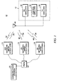
- a communication arrangement shown generally at 10, includes a multi-mode mobile station 12 capable of transceiving communication signals with a plurality, here three, radio communication systems.
- the mobile station 12 forms a dual-band, tri-mode, cellular mobile station selectably operable in three separate mobile communication systems. While the following description shall describe the mobile station 12 with respect to such an implementation, it should be understood that other embodiments of the present invention can analogously be implemented to be operable in other types of communication systems.
- a first network infrastructure 14, second network infrastructure 16, and a third network infrastructure 18 are installed and are permitting of radio communications with the mobile station 12 when the mobile station is positioned in a geographical area encompassed by the network infrastructure of the respective communication systems.
- the separate network infrastructures may be overlaid, or partially overlaid, upon one another.
- the network infrastructure may be installed at separate geographical areas, and the mobile station communicates with the respective one of the separate radio communication systems when the mobile station is positioned in the geographical area encompassed by such respective communication system.
- the network infrastructure 14 is here representative of a PCS-band, CDMA (code division, multiple-access) mobile communication system operable at approximately 1.9 GHz.
- the network infrastructure 16 is representative of a cellular-band, CDMA mobile communication system operable at about 800 MHz.
- the network infrastructure 18 is representative of the network infrastructure of a cellular-band, AMPS (advanced mobile phone service) mobile communication system operable also at about 800 MHz. It should be noted that the terminology of cellular and mobile shall be, at times, used interchangeably herein.
- the network infrastructure 14-18 of the respective communication systems are coupled to a PSTN (public-switched, telephonic network) 22, in conventional manner.
- a communication station 24 is also shown to be coupled to the PSTN.
- the communication station 24 is exemplary of a communication station with which communications can be effectuated with the mobile station.
- first downlink communication signals 28 and first uplink signals 32 are representative of the signals communicated between the network infrastructure and the mobile station.
- first downlink communication signals 28 and first uplink signals 32 are representative of the signals communicated between the network infrastructure and the mobile station.
- second downlink communication signals 34 and second uplink communication signals 36 are representative of communication of the signals between the network infrastructure and the mobile station.
- third downlink communication signals 38 and third uplink communication signals 42 are representative of signals communicated during operation of the third cellular communication system.
- the mobile station 12 is here shown to include transmitter circuitry 44 and receiver circuitry 46.
- Information sourced at the mobile station is acted upon by the transmitter circuitry and transduced by an antenna transducer 48 to form, selectably, the uplink communication signals, 32, 36, and 42, as appropriate.
- the receiver circuitry is selectably operable to act upon the signals applied thereto.
- the mobile station 12 is further shown to include control circuitry 52 operable to control operation of the transmitter and receiver circuitry 44 and 46, respectively.
- the control circuitry controls operation of the respective circuitry to cause operation of the mobile station in a selected one of the different cellular communication systems with which the mobile station 12 is operable. By appropriate control over which of the communication systems with which the mobile station is operable, an available one, or a desired one, of the cellular communication systems, is caused to be utilized by the mobile station.
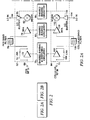
- FIG. 2 illustrates the receiver circuitry 46 of an embodiment of the present invention.
- the receiver circuitry 46 forms a portion of the mobile station 12 of a dual-band, tri-mode mobile station. While the circuitry 46 of the exemplary implementation shown in the Figure is representative of the circuitry of such a device, in other implementations, the receiver circuitry is alternately configured to be operable in selected communication systems, as appropriate.
- the receiver circuitry 46 here includes a first receive chain portion 62, a second receive chain portion 64, a common receive chain portion 66, and a third receive chain portion 68.
- the first receive chain portion 62 includes a front end side coupled to the antenna transducer 48 (shown in Figure 1), thereby to receive indications of the first downlink communication signal 28 (shown in Figure 1), when detected at the mobile station of which the receiver circuitry forms a portion.
- the indications are applied to the portion 62 on the line 69, here indicated as "PCS RF In.”
- the second receive chain portion 64 also includes a front end side, also coupled to the antenna transducer (shown in Figure 1), thereby to receive indications of the second downlink communication signal 34 (shown in Figure 1).
- the indications are applied to the portion 64 on the line 71, here indicated as "CELLULAR RF In.”
- the first and second receive chain portions 62 and 64 further define back end sides to which the common receive chain portion 66 is coupled.
- the first and second receive chain portions are coupled to the common receive chain portion in a wired-OR configuration in which indications of either the first receive signal, once acted upon by the first receive chain portion, or indications of the second receive chain portion once acted upon by the second receive chain portion are provided to the common receive chain portion to be acted further upon thereat.
- the third receive chain portion 68 is also coupled to the back end side of the second receive chain portion 64 and is selectably operable, alternate to operation of the common receive chain portion.
- the first receive chain portion 62 forms an RF (radio frequency)-stage of a PCS-band receive operable at about 1.9 GHz.
- Indications of the first receive signal, detected at the antenna transducer 48 and converted into electrical form thereat, are provided to a low-noise amplifier (LNA) 72.
- the LNA 72 is a switched amplifier which permits bypassing of the amplifier if determinations are made that amplification at the LNA is unnecessary. Such switching is performed by a switch element 74. Selection of the switch position of the switch element 74 is made by biasing and switching circuitry 75 to position the switch element 74 in a desired switch position.
- the LNA 72 is coupled to a PCS-band filter 76 which has a passband to pass signal frequency within the PCS passband.
- Signal frequencies passed by the filter 76 are applied to an RF amplifier 78 to be amplified thereat.
- the amplifier 78 is biased by shared biasing circuitry 80.
- the signal is provided to a first input of a mixer 82.
- a down mixing signal, the "LO In" signal, generated on the line 84 is applied to a second input of the mixer 82 by way of an isolating buffer 85.
- the buffer 85 is biased by shared biasing circuitry 86.
- the mixer operates as a down-mixer to down-convert in frequency the amplified signal applied to the first input of the mixer to form an IF (intermediate frequency)-frequency signal on the line 87 extending from an output of the mixer.
- the IF signal is applied to an IF-stage amplifier 88, here a differential amplifier.
- the amplifier is biased by shared biasing circuitry 90.
- Differential, amplified signals are generated on the lines 92, and the lines 92 are connected to the common receive chain portion 66.
- the second receive chain portion 64 forms an RF-stage of a cellular-band receiver operable at cellular frequencies of about 800 MHz.
- Indications of the second downlink signals detected at the antenna transducer 48 and converted into electrical form thereat are applied to an input of a low-noise amplifier (LNA) 102.
- the LNA 102 is a switched amplifier which permits bypassing of the amplifier if determinations are made that amplification at the LNA is unnecessary. Such switching is performed by a switch element 104. Selection of the switch position of the switch element 104 is made by the shared biasing and switching circuitry 75.
- the LNA 102 is coupled to a cellular band filter 106 having a passband to pass signal frequencies within a cellular band of approximately 800 MHz.
- Signal frequencies passed by the filter 106 are amplified by an RF amplifier 108.
- the amplifier 108 is biased by biasing circuitry 80.
- Amplified signals are applied to a first input of a mixer 112.
- a down-mixing signal, the "LO In" signal, generated on the line 114 is applied to a second input of the mixer 112 by way of an isolating buffer 115.
- the buffer 115 is biased by shared biasing circuitry 86.
- the mixer 112 is operable to down-convert the indications of the second receive signal applied to the first input of the mixer in frequency to an IF frequency.
- An IF signal is formed on the line 116 at an output of the mixer 112.
- the line 116 is coupled to an input of a differential amplifier 118 operable to generate amplified signals on the line 92.
- the amplifier is biased by the shared biasing circuitry 90.
- the lines 92 are connected to the common receive chain portion 66.
- the line 116 is also coupled to an input of an amplifier 122.
- the amplifier 122 an output line of which is coupled to the third receive chain portion 68.
- the amplifier is selectably operable to amplify the IF signal formed on the line 116 and to apply such signal, once amplified, to an IF filter 124.
- Signal frequencies within the passband of the filter 124 are applied to a receiver backend FM Demodulation element 126.
- the element 126 performs functions such as baseband down conversion and demodulation operations.
- the FM demodulation can be performed by digital or analog methods.
- the lines 92 connected to the differential outputs of the IF amplifiers 88 and 118 of the first and second receive chain portions 62 and 64, respectively, are coupled to an IF filter 144 which forms a portion of the common receive chain portion 66.
- the filter 144 exhibits a passband corresponding to the passband to pass signal frequencies of CDMA signals generated during operation of a cellular, CDMA system, either of those operable at a PCS-band frequency or operable at a cellular-band frequency.
- Signal frequencies passed by the filter 144 are applied to a receiver backend I/Q Demodulation element 146.
- the element 146 performs functions such as baseband down conversion and demodulation operations.
- the receiver circuitry 46 shown in the Figure is of reduced circuit element count relative to conventional such constructions because circuit paths are shared amongst the circuit paths required for operation of the different mode of which the mobile station is operable. Advantage is taken of the fact that the mobile station is operable in a single mode at a time. That is to say, when the mobile station is operable to communicate pursuant to the first communication network, here a PCS-band, CDMA system, only the circuit path relating to that communication system is operable.
- the IF-stage amplifiers 88, 118, and 122 are selectably powered. Such selective powering of the amplifiers is determinative of operation of the receiver circuitry.
- the IF-stage amplifier 88 When the mobile station of which the receiver circuitry forms a portion is to be operable in a PCS-band, CDMA mode, the IF-stage amplifier 88 is powered while the amplifiers 118 and 122 are not powered. Thereby, a receive chain, formed of the receive chain portion 62 and the common receive chain portion 66 acts upon signals received at the mobile station.
- the amplifier 118 When, conversely, the mobile station is to be operable in the cellular-band, CDMA mode, the amplifier 118 is caused to be powered while the amplifiers 88 and 122 are caused not to be powered.
- the second receive chain portion 64 and the common receive chain portion 66 form a receive chain which acts upon the signals received at the mobile station.
- the amplifier 122 is caused to be powered, and the amplifiers 88 and 118 are caused not to be powered.
- the second receive chain portion 64 and the third receive chain portion 68 form a receive chain for acting upon signals received at the mobile station.
- other manners are used by which to selectably connect the different portions 62, 64, 66, and 68 to form a receive chain, operable as desired.
- the shared circuitry 75, 80, 86, and 90 is operable with a selected one of the first receive chain portion with a second receive chain portion. Circuit element-count is thereby reduced, relative to conventional constructions of the receiver circuitry 48.
- Figure 3 illustrates a method, shown generally at 172, of an embodiment of the present invention.
- the method selectably acts upon a first receive signal and at least a second receive signal when received at a multi-mode radio receiver operable to receive first receive signals generated during operation of a first radio communication system and to receive at least second receive signals generated during operation of at least a second radio communication system.
- indications of the first receive signal, if received at the multi-mode receiver are applied to a first receive chain portion.
- indications of the second receive signal, if received at the multi-mode receiver, are applied to a second receive chain portion.
- the indications of the first receive signal are selectably acted upon at the first receive chain portion, and the indications of the second receive signal are selectably acted upon at the second receive chain portion. Either one, but not both, of the first receive chain portion and the second receive chain portion are operable during the selected period.
- indications of a selected one of the indications of the receive signal and the indication of the second receive signal are applied to a common receive chain portion.
- the indications of the selected one of the indications of the first and second receive signal, applied to the common receive chain portion are further acted upon.
Landscapes
- Engineering & Computer Science (AREA)
- Computer Networks & Wireless Communication (AREA)
- Signal Processing (AREA)
- Mobile Radio Communication Systems (AREA)
- Superheterodyne Receivers (AREA)
- Circuits Of Receivers In General (AREA)
- Transceivers (AREA)
Applications Claiming Priority (2)
| Application Number | Priority Date | Filing Date | Title |
|---|---|---|---|
| US09/317,660 US6292474B1 (en) | 1999-05-24 | 1999-05-24 | Multi-frequency band nyktu-mode radio receiver and associated method having shared circuit elements |
| EP00936226A EP1181779B1 (de) | 1999-05-24 | 2000-05-23 | Verfahren und vorrichtung zum multiband und multimode funkempfäng mit gemeinsamen schaltungselementen |
Related Parent Applications (1)
| Application Number | Title | Priority Date | Filing Date |
|---|---|---|---|
| EP00936226A Division EP1181779B1 (de) | 1999-05-24 | 2000-05-23 | Verfahren und vorrichtung zum multiband und multimode funkempfäng mit gemeinsamen schaltungselementen |
Publications (1)
| Publication Number | Publication Date |
|---|---|
| EP1838005A1 true EP1838005A1 (de) | 2007-09-26 |
Family
ID=23234702
Family Applications (2)
| Application Number | Title | Priority Date | Filing Date |
|---|---|---|---|
| EP00936226A Expired - Lifetime EP1181779B1 (de) | 1999-05-24 | 2000-05-23 | Verfahren und vorrichtung zum multiband und multimode funkempfäng mit gemeinsamen schaltungselementen |
| EP07013025A Withdrawn EP1838005A1 (de) | 1999-05-24 | 2000-05-23 | Multifrequenzband, Radioempfänger mit mehreren Betriebsarten und entsprechendes Verfahren mit gemeinsam genutzten Schaltelementen |
Family Applications Before (1)
| Application Number | Title | Priority Date | Filing Date |
|---|---|---|---|
| EP00936226A Expired - Lifetime EP1181779B1 (de) | 1999-05-24 | 2000-05-23 | Verfahren und vorrichtung zum multiband und multimode funkempfäng mit gemeinsamen schaltungselementen |
Country Status (7)
| Country | Link |
|---|---|
| US (1) | US6292474B1 (de) |
| EP (2) | EP1181779B1 (de) |
| KR (1) | KR100435276B1 (de) |
| CN (2) | CN1332510C (de) |
| AU (1) | AU5157400A (de) |
| DE (1) | DE60036208C5 (de) |
| WO (1) | WO2000072456A1 (de) |
Cited By (1)
| Publication number | Priority date | Publication date | Assignee | Title |
|---|---|---|---|---|
| US8150361B2 (en) | 2004-08-13 | 2012-04-03 | Nokia Corporation | Single chip amplifier and oscillator having similar resonant circuit topology |
Families Citing this family (37)
| Publication number | Priority date | Publication date | Assignee | Title |
|---|---|---|---|---|
| US6542481B2 (en) | 1998-06-01 | 2003-04-01 | Tantivy Communications, Inc. | Dynamic bandwidth allocation for multiple access communication using session queues |
| US6081536A (en) | 1997-06-20 | 2000-06-27 | Tantivy Communications, Inc. | Dynamic bandwidth allocation to transmit a wireless protocol across a code division multiple access (CDMA) radio link |
| JP3601950B2 (ja) * | 1997-09-16 | 2004-12-15 | 株式会社東芝 | 通信装置およびネットワーク情報提示方法 |
| US9525923B2 (en) | 1997-12-17 | 2016-12-20 | Intel Corporation | Multi-detection of heartbeat to reduce error probability |
| US7394791B2 (en) | 1997-12-17 | 2008-07-01 | Interdigital Technology Corporation | Multi-detection of heartbeat to reduce error probability |
| US7936728B2 (en) | 1997-12-17 | 2011-05-03 | Tantivy Communications, Inc. | System and method for maintaining timing of synchronization messages over a reverse link of a CDMA wireless communication system |
| US6222832B1 (en) | 1998-06-01 | 2001-04-24 | Tantivy Communications, Inc. | Fast Acquisition of traffic channels for a highly variable data rate reverse link of a CDMA wireless communication system |
| US8134980B2 (en) | 1998-06-01 | 2012-03-13 | Ipr Licensing, Inc. | Transmittal of heartbeat signal at a lower level than heartbeat request |
| US7773566B2 (en) | 1998-06-01 | 2010-08-10 | Tantivy Communications, Inc. | System and method for maintaining timing of synchronization messages over a reverse link of a CDMA wireless communication system |
| US7327775B1 (en) * | 1999-12-23 | 2008-02-05 | Nokia Corporation | CDMA receiver |
| WO2001058044A2 (en) | 2000-02-07 | 2001-08-09 | Tantivy Communications, Inc. | Minimal maintenance link to support synchronization |
| US7054290B1 (en) * | 2000-03-07 | 2006-05-30 | Telefonaktiebolaget Lm Ericsson (Publ) | Methods and apparatus for dual mode operation in a wireless communication system |
| WO2002009378A1 (en) * | 2000-07-24 | 2002-01-31 | Matsushita Electric Industrial Co., Ltd. | Radio communication apparatus and radio communication method |
| US6665284B1 (en) * | 2000-07-31 | 2003-12-16 | Nokia Mobile Phones, Ltd. | Apparatus, and associated method, for receiving data at a radio device |
| US8155096B1 (en) | 2000-12-01 | 2012-04-10 | Ipr Licensing Inc. | Antenna control system and method |
| US7551663B1 (en) | 2001-02-01 | 2009-06-23 | Ipr Licensing, Inc. | Use of correlation combination to achieve channel detection |
| US6954448B2 (en) | 2001-02-01 | 2005-10-11 | Ipr Licensing, Inc. | Alternate channel for carrying selected message types |
| EP2479904B1 (de) | 2001-06-13 | 2017-02-15 | Intel Corporation | Vorrichtungen zur Senden eines Herzschlagsignals mit einem niedrigeren Pegel als eine Herzschlaganforderung |
| US6985698B2 (en) * | 2001-11-14 | 2006-01-10 | Koninklijke Philips Electronics N.V. | Impedeance matching circuit for a multi-band radio frequency device |
| AU2003286365A1 (en) * | 2002-12-30 | 2004-07-22 | Koninklijke Philips Electronics N.V. | Multimode receiver. |
| US7003274B1 (en) | 2003-03-05 | 2006-02-21 | Cisco Systems Wireless Networking (Australia) Pty Limited | Frequency synthesizer and synthesis method for generating a multiband local oscillator signal |
| US20040218683A1 (en) * | 2003-05-01 | 2004-11-04 | Texas Instruments Incorporated | Multi-mode wireless devices having reduced-mode receivers |
| US7483682B2 (en) * | 2004-04-08 | 2009-01-27 | Clearcalm Inc. | Dual-band radio enabled lapel mounted audio and signal handling system and method |
| WO2006105010A1 (en) * | 2005-03-25 | 2006-10-05 | Neocific, Inc. | Methods and apparatus for cellular broadcasting and communication system |
| CN100380829C (zh) * | 2005-01-17 | 2008-04-09 | 英华达(南京)科技有限公司 | 一种采用单天线的gsm及phs双模手机 |
| US7796956B2 (en) * | 2005-05-03 | 2010-09-14 | Telefonaktiebolaget L M Ericsson (Publ) | Receiver for a multi-antenna, multi-band radio |
| US8155098B2 (en) | 2005-06-09 | 2012-04-10 | Neocific, Inc. | Methods and apparatus for power efficient broadcasting and communication systems |
| CN101303403B (zh) * | 2007-06-11 | 2011-01-26 | 杭州中科微电子有限公司 | 多模式卫星导航接收射频前端芯片 |
| KR101149869B1 (ko) * | 2007-08-10 | 2012-05-25 | 삼성전자주식회사 | 이동통신 단말기에서 멀티 주파수를 지원하기 위한 동기획득 방법 및 장치 |
| WO2012050838A1 (en) | 2010-09-28 | 2012-04-19 | Neocific, Inc. | Methods and apparatus for flexible use of frequency bands |
| CN102291840A (zh) * | 2011-08-29 | 2011-12-21 | 中兴通讯股份有限公司 | 一种gsm与lte基带单元、双模系统及频谱调度方法 |
| US9246436B2 (en) * | 2012-07-16 | 2016-01-26 | Linear Technology Corporation | Low power radio receiver |
| KR101413970B1 (ko) * | 2012-12-28 | 2014-07-04 | 주식회사 레이믹스 | 다중 대역 rf 수신기 |
| US9496840B2 (en) | 2014-05-16 | 2016-11-15 | Linear Technology Corporation | Radio receiver |
| US9893752B2 (en) * | 2014-10-31 | 2018-02-13 | Skyworks Solutions, Inc. | Diversity receiver front end system with variable-gain amplifiers |
| US10181870B2 (en) | 2015-08-27 | 2019-01-15 | Telefonaktiebolaget Lm Ericsson (Publ) | Method and dual band radio receiver for handling analog dual band radio signal |
| US10063318B2 (en) | 2016-12-01 | 2018-08-28 | Corning Optical Communications Wireless Ltd | Combining uplink radio frequency (RF) communications signals in a remote unit in a wireless distribution system (WDS) using a differential mixer |
Citations (5)
| Publication number | Priority date | Publication date | Assignee | Title |
|---|---|---|---|---|
| WO1997030523A1 (en) * | 1996-02-16 | 1997-08-21 | Northern Telecom Limited | A dual-mode radio architecture |
| DE19705752A1 (de) * | 1996-02-14 | 1997-10-30 | Sony Corp | Sendesignal-Empfangsgerät und Impulszähldemodulatoren |
| EP0813312A2 (de) * | 1996-06-10 | 1997-12-17 | Matsushita Electric Industrial Co., Ltd. | Multibandkommunikationsgerät |
| EP0823790A2 (de) * | 1996-08-07 | 1998-02-11 | Nokia Mobile Phones Ltd. | Mobiles Zweibandfunkgerät mit kreuzverbundenen Sender- und Empfänger-Schaltungen |
| EP0823788A2 (de) * | 1996-08-08 | 1998-02-11 | Matsushita Electric Industrial Co., Ltd. | Empfangsmischer für ein mobiles Funkgerät mit mehreren Modulationsmoden und Frequenzbereichen |
Family Cites Families (2)
| Publication number | Priority date | Publication date | Assignee | Title |
|---|---|---|---|---|
| US5054114A (en) * | 1988-09-27 | 1991-10-01 | Rockwell International Corporation | Broadband RF transmit/receive switch |
| FR2664447B1 (fr) * | 1990-07-04 | 1992-09-18 | Matra Communication | Dispositif de couplage d'une antenne a des organes de radio communication. |
-
1999
- 1999-05-24 US US09/317,660 patent/US6292474B1/en not_active Expired - Lifetime
-
2000
- 2000-05-23 AU AU51574/00A patent/AU5157400A/en not_active Abandoned
- 2000-05-23 KR KR10-2001-7015053A patent/KR100435276B1/ko not_active Expired - Lifetime
- 2000-05-23 CN CNB008107289A patent/CN1332510C/zh not_active Expired - Lifetime
- 2000-05-23 CN CN2007101280245A patent/CN101098153B/zh not_active Expired - Lifetime
- 2000-05-23 EP EP00936226A patent/EP1181779B1/de not_active Expired - Lifetime
- 2000-05-23 WO PCT/US2000/014184 patent/WO2000072456A1/en not_active Ceased
- 2000-05-23 DE DE60036208.6T patent/DE60036208C5/de not_active Expired - Lifetime
- 2000-05-23 EP EP07013025A patent/EP1838005A1/de not_active Withdrawn
Patent Citations (5)
| Publication number | Priority date | Publication date | Assignee | Title |
|---|---|---|---|---|
| DE19705752A1 (de) * | 1996-02-14 | 1997-10-30 | Sony Corp | Sendesignal-Empfangsgerät und Impulszähldemodulatoren |
| WO1997030523A1 (en) * | 1996-02-16 | 1997-08-21 | Northern Telecom Limited | A dual-mode radio architecture |
| EP0813312A2 (de) * | 1996-06-10 | 1997-12-17 | Matsushita Electric Industrial Co., Ltd. | Multibandkommunikationsgerät |
| EP0823790A2 (de) * | 1996-08-07 | 1998-02-11 | Nokia Mobile Phones Ltd. | Mobiles Zweibandfunkgerät mit kreuzverbundenen Sender- und Empfänger-Schaltungen |
| EP0823788A2 (de) * | 1996-08-08 | 1998-02-11 | Matsushita Electric Industrial Co., Ltd. | Empfangsmischer für ein mobiles Funkgerät mit mehreren Modulationsmoden und Frequenzbereichen |
Cited By (1)
| Publication number | Priority date | Publication date | Assignee | Title |
|---|---|---|---|---|
| US8150361B2 (en) | 2004-08-13 | 2012-04-03 | Nokia Corporation | Single chip amplifier and oscillator having similar resonant circuit topology |
Also Published As
| Publication number | Publication date |
|---|---|
| EP1181779B1 (de) | 2007-08-29 |
| AU5157400A (en) | 2000-12-12 |
| KR100435276B1 (ko) | 2004-06-11 |
| WO2000072456A8 (en) | 2008-02-28 |
| WO2000072456A9 (en) | 2002-05-02 |
| CN1332510C (zh) | 2007-08-15 |
| US6292474B1 (en) | 2001-09-18 |
| WO2000072456A1 (en) | 2000-11-30 |
| DE60036208T2 (de) | 2007-12-20 |
| EP1181779A1 (de) | 2002-02-27 |
| CN101098153A (zh) | 2008-01-02 |
| DE60036208D1 (de) | 2007-10-11 |
| CN101098153B (zh) | 2012-02-22 |
| KR20020012238A (ko) | 2002-02-15 |
| CN1364343A (zh) | 2002-08-14 |
| DE60036208C5 (de) | 2017-01-26 |
Similar Documents
| Publication | Publication Date | Title |
|---|---|---|
| US6292474B1 (en) | Multi-frequency band nyktu-mode radio receiver and associated method having shared circuit elements | |
| EP0829970B1 (de) | Zweimodusfunkgerät für TDMA und FDD | |
| JP4494650B2 (ja) | 共有機能ブロックcdma/gsm通信トランシーバ用システム及びプロセス | |
| US6535748B1 (en) | Wireless communication transceiver having a dual mode of operation | |
| US6208844B1 (en) | System and process for shared functional block communication transceivers with GPS capability | |
| US6195563B1 (en) | Radio receiver and radio transmitter | |
| KR101047158B1 (ko) | 소프트웨어 정의 다중 전송 아키텍처 | |
| US8060082B2 (en) | Ancillary terrestrial component services using multiple frequency bands | |
| US8792395B2 (en) | Wireless transceiver system for supporting dual mode | |
| JPH07221684A (ja) | 移動体通信の無線端末装置 | |
| US20020123306A1 (en) | Channelized booster amplifier for cellular communications | |
| CA2420077C (en) | Block communication transceivers with gps capability | |
| HK1113442A (en) | Multi-frequency band, multi-mode radio receiver, and associated method, having shared circuit elements | |
| CN121150793B (zh) | 卫星通信导航一体化的射频系统、配置方法、设备及介质 | |
| KR100237446B1 (ko) | 한국형 개인 휴대통신 서비스 단말기 | |
| WO2000031886A1 (en) | A transceiver |
Legal Events
| Date | Code | Title | Description |
|---|---|---|---|
| PUAI | Public reference made under article 153(3) epc to a published international application that has entered the european phase |
Free format text: ORIGINAL CODE: 0009012 |
|
| AC | Divisional application: reference to earlier application |
Ref document number: 1181779 Country of ref document: EP Kind code of ref document: P |
|
| AK | Designated contracting states |
Kind code of ref document: A1 Designated state(s): DE FR GB IT |
|
| 17P | Request for examination filed |
Effective date: 20080326 |
|
| AKX | Designation fees paid |
Designated state(s): DE FR GB IT |
|
| 17Q | First examination report despatched |
Effective date: 20080603 |
|
| REG | Reference to a national code |
Ref country code: HK Ref legal event code: DE Ref document number: 1113442 Country of ref document: HK |
|
| STAA | Information on the status of an ep patent application or granted ep patent |
Free format text: STATUS: THE APPLICATION IS DEEMED TO BE WITHDRAWN |
|
| 18D | Application deemed to be withdrawn |
Effective date: 20081216 |
|
| REG | Reference to a national code |
Ref country code: HK Ref legal event code: WD Ref document number: 1113442 Country of ref document: HK |