EP1839785A2 - Dispositif destiné à la fixation de tiges et tour doté d'un tel dispositif - Google Patents
Dispositif destiné à la fixation de tiges et tour doté d'un tel dispositif Download PDFInfo
- Publication number
- EP1839785A2 EP1839785A2 EP07102902A EP07102902A EP1839785A2 EP 1839785 A2 EP1839785 A2 EP 1839785A2 EP 07102902 A EP07102902 A EP 07102902A EP 07102902 A EP07102902 A EP 07102902A EP 1839785 A2 EP1839785 A2 EP 1839785A2
- Authority
- EP
- European Patent Office
- Prior art keywords
- sleeve
- rod
- fluid
- hose
- lathe
- Prior art date
- Legal status (The legal status is an assumption and is not a legal conclusion. Google has not performed a legal analysis and makes no representation as to the accuracy of the status listed.)
- Withdrawn
Links
Images



Classifications
-
- B—PERFORMING OPERATIONS; TRANSPORTING
- B23—MACHINE TOOLS; METAL-WORKING NOT OTHERWISE PROVIDED FOR
- B23B—TURNING; BORING
- B23B13/00—Arrangements for automatically conveying or chucking or guiding stock
- B23B13/02—Arrangements for automatically conveying or chucking or guiding stock for turning-machines with a single working-spindle
-
- B—PERFORMING OPERATIONS; TRANSPORTING
- B23—MACHINE TOOLS; METAL-WORKING NOT OTHERWISE PROVIDED FOR
- B23B—TURNING; BORING
- B23B13/00—Arrangements for automatically conveying or chucking or guiding stock
- B23B13/08—Arrangements for reducing vibrations in feeding-passages or for damping noise
-
- B—PERFORMING OPERATIONS; TRANSPORTING
- B23—MACHINE TOOLS; METAL-WORKING NOT OTHERWISE PROVIDED FOR
- B23B—TURNING; BORING
- B23B31/00—Chucks; Expansion mandrels; Adaptations thereof for remote control
- B23B31/02—Chucks
- B23B31/24—Chucks characterised by features relating primarily to remote control of the gripping means
- B23B31/30—Chucks characterised by features relating primarily to remote control of the gripping means using fluid-pressure means in the chuck
- B23B31/305—Chucks characterised by features relating primarily to remote control of the gripping means using fluid-pressure means in the chuck the gripping means is a deformable sleeve
-
- B—PERFORMING OPERATIONS; TRANSPORTING
- B23—MACHINE TOOLS; METAL-WORKING NOT OTHERWISE PROVIDED FOR
- B23B—TURNING; BORING
- B23B2270/00—Details of turning, boring or drilling machines, processes or tools not otherwise provided for
- B23B2270/02—Use of a particular power source
- B23B2270/027—Pneumatics
Definitions
- the present invention relates to a device for supporting rods, in particular for lathes, with at least one sleeve which can be inserted into a hollow spindle, wherein in the sleeve, a rod is clamped, according to the preamble of claim 1. Furthermore, the invention relates to a Lathe according to the preamble of claim 12.
- the DE 7 339 154 shows a rod guide device on a clamping device of a lathe, in which a rod guide tube has an inner clothing for reducing vibrations.
- a rod guide tube has an inner clothing for reducing vibrations.
- radially resilient support units are provided at regular intervals.
- the disadvantage of such tensioning devices is that they can only be adapted poorly to different diameters of the fixed workpieces.
- rod holders are only bad for an automatic longitudinal promotion of the rod, since the clamping means are permanently applied to the rod.
- a similar device for holding rod material on a lathe is in the DE 7 607 386 shown.
- this holder sleeves are arranged with spring elements in a machine spindle, which fix the rod material should. These sleeves are effective only for certain diameters of rod material and also the vibration behavior of rods of different lengths is considered only poorly.
- the DE 28 22 569 C2 discloses a device for feeding material bars for automatic lathes, in which a rod is supported on stands outside of the lathe to prevent sagging.
- a sleeve is provided, on which an oil-impingable tube membrane is formed for pressing against the rod.
- An insert of the device within the automatic lathe is not provided.
- the sleeve for fixing the rod on the inside of elastic means which can be clamped by pressurizing a fluid against the rod.
- the elastic means can be pressed individually against the rod, wherein a certain tolerance compensation with respect to the diameter and the outer contour of the rod can be done.
- the elastic means of the sleeve can be moved further inward and also the contact pressure can be adjusted by the pressure.
- this device for holding rods is also suitable for automatic rod conveying means, since after releasing the pressure, the rod is again smoothly displaceable within a hollow spindle and then an automatic centering can be done by the pressurization with the fluid.
- the fluid-loaded chamber of the radially outer side has at least one elastic wall section, which is movable against the surrounding spindle.
- the pressurization with the fluid is switchable.
- the duration of the fixation can be adjusted manually or automatically via a controller as required.
- an inwardly movable elastic hose section is arranged on the at least one sleeve.
- the rod may be annularly surrounded by the elastic tube portion and is automatically centered when setting. It also ensures that the same contact pressure prevails over the entire circumference.
- the hose section can be protected inside via a fabric hose, preferably made of a stainless steel mesh.
- the tube portion may be fixed at opposite ends of the sleeve, so that the effective area of the tube portion is reduced to a reasonable degree.
- an annular clamping cone can be used at the end to fix the hose section and / or the fabric hose.
- the elastic wall portion may preferably be formed as a displaceable rubber block, wherein preferably distributed over the circumference of several such rubber blocks are arranged.
- a plurality of sleeves are provided, whose fluid can be acted upon chambers are interconnected. Then, the desired length of the device for holding rods can be assembled as needed.
- a stop is arranged on one of the sleeves in the interior. This allows the user to insert a rod into the device to a desired length and then fix the rod manually or automatically without having to take a measurement.
- compressed air is preferably used to act on the chamber.
- gaseous or liquid fluids which are harmless in compressed air minor leaks.
- a rotary feedthrough is provided on a sleeve end, to which a conduit for supplying the fluid is connected. Because the sleeve is rotatable together with the spindle, so that for the pressurization a rotary feedthrough with a rotatable inner part and a fixed outer part with a line connection is required, which may be arranged for example on the opposite side to the lining.
- a lathe for machining rod-shaped workpieces equipped with a device for supporting rods.
- a schematically shown headstock 1 a lathe comprises a spindle motor 2, on one side of a chuck 3 is provided for clamping workpieces. On the chuck 3 movable jaws 4 are arranged for this purpose. On the opposite side, a clamping cylinder 5 is provided, at the end a rotary feedthrough 6 is fixed with a compressed air connection.
- a hollow spindle or a pull tube is arranged, in which a workpiece to be machined can be inserted. So that the inserted workpieces, preferably rods or other round profiles are not exposed to unnecessary vibrations, a device for supporting rods within the spindle motor 2 and the clamping cylinder 5 is arranged, which has a plurality of adjacently arranged sleeves 7.
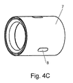
- a plurality of sleeves 7 are connected to each other, wherein at the periphery a plurality of rubber blocks 8 are provided which can be applied to the inside of a tubular spindle.
- FIGS. 4A to 4C Such a sleeve 7 is shown in detail in FIGS. 4A to 4C.
- the sleeve 7 made of metal has a front side formed by a plurality of holes 9 channel for supplying a fluid, preferably compressed air.
- a transition 10 is formed to a chamber 11 which is disposed on the outboard side adjacent to a rubber block 8.
- the chamber 11 is surrounded by a rubber tube 12, on the inside of a fabric tube 16, preferably made of stainless steel is arranged.
- the rubber tube 12 is fixed on opposite sides of the sleeve 7, for which purpose a clamping cone 13 and a threaded ring 14 are provided. As a result, one end of the tube section 12 is respectively clamped to a wall of the sleeve 7.
- a guide cone 15 is arranged, which has an inwardly pointing tip 17 which abuts a portion of the fabric tube 16, so that the fabric tube 16 is fixed independently of the rubber tube 12, wherein it is possible, the fabric tube sixteenth movable between tip 17 and clamping cone 13 to hold.
- the fastening mechanism is identical on both sides of the sleeve 7.
- a rod is disposed within a sleeve 7, by applying the device for supporting rods with compressed air, the compressed air can pass through the channels 9, the transitions 10 in the respective chambers 11, wherein by the pressure in the chamber 11 of the rubber tube 12th is moved radially inwardly while also moving the protective fabric tube 16 inwardly against the rod arranged there.
- the rubber block 8 is pushed slightly outwards, so that it bears against the inside of the tubular spindle. As a result, the rod is clamped within the spindle and can no longer vibrate.
- the application of compressed air can be turned off and due to the elasticity of the rubber tube 12 and the fabric tube 16, they move radially outward again and release the rod. This can then be moved manually or automatically in the next position, in which then the admission of the chamber 11 can be done with compressed air to fix the rod again.
- FIG. 5A and 5B Shown in Figures 5A and 5B is a modified embodiment of the invention in which the rod holding device comprises only three adjacent sleeves 7 arranged on a chuck 3 of a lathe.
- the shorter design of the device for holding rods has the advantage that an application of compressed air must be made via fewer sleeves 7.
- the length of the device for supporting rods can be adapted to the desired application.
- the device for supporting rods can be processed particularly well and non-round material rods, as they are held fixed in the interior of the spindle. Due to the flexible design of the rubber hose and the fabric hose, the device can also be adapted well to different diameters of rods.
- a wire mesh is provided which has the necessary flexibility.
- the rubber hose it is also possible only set the rubber hose to the sleeve 7, in which case the wear is slightly larger.
- other elastic hose material can be used instead of the rubber hose.
- another mechanism can be used to define a tube section, wherein the length of the individual tube sections is dimensioned so that they have sufficient flexibility but also move back to the outside after the application of pressure of the fluid.
- the application of compressed air can be done both automatically by a controller and manually by valves.
Landscapes
- Engineering & Computer Science (AREA)
- Mechanical Engineering (AREA)
- Turning (AREA)
Applications Claiming Priority (1)
| Application Number | Priority Date | Filing Date | Title |
|---|---|---|---|
| DE200610010359 DE102006010359B4 (de) | 2006-03-07 | 2006-03-07 | Vorrichtung zur Halterung von Stangen und Drehmaschinen mit solch einer Vorrichtung |
Publications (2)
| Publication Number | Publication Date |
|---|---|
| EP1839785A2 true EP1839785A2 (fr) | 2007-10-03 |
| EP1839785A3 EP1839785A3 (fr) | 2008-05-14 |
Family
ID=38137335
Family Applications (1)
| Application Number | Title | Priority Date | Filing Date |
|---|---|---|---|
| EP07102902A Withdrawn EP1839785A3 (fr) | 2006-03-07 | 2007-02-22 | Dispositif destiné à la fixation de tiges et tour doté d'un tel dispositif |
Country Status (2)
| Country | Link |
|---|---|
| EP (1) | EP1839785A3 (fr) |
| DE (1) | DE102006010359B4 (fr) |
Cited By (2)
| Publication number | Priority date | Publication date | Assignee | Title |
|---|---|---|---|---|
| CN111822447A (zh) * | 2020-06-28 | 2020-10-27 | 济南金威刻科技发展有限公司 | 基于光纤激光器的激光清洗设备 |
| CN113059204A (zh) * | 2021-03-30 | 2021-07-02 | 中国兵器装备集团自动化研究所有限公司 | 一种软性棒料夹持工装及夹持系统 |
Families Citing this family (2)
| Publication number | Priority date | Publication date | Assignee | Title |
|---|---|---|---|---|
| DE202010002666U1 (de) * | 2010-02-23 | 2010-06-10 | LÖFFLER, Kai | Stangenlademagazin |
| DE102021110637B4 (de) | 2021-04-26 | 2023-02-23 | Anton Heiß | Automatische Drehmaschine |
Family Cites Families (6)
| Publication number | Priority date | Publication date | Assignee | Title |
|---|---|---|---|---|
| GB1277096A (en) * | 1968-06-13 | 1972-06-07 | Hydra Lock Corp | Improvements in or relating to hydrostatic work-holding devices |
| DE7339154U (de) * | 1973-11-02 | 1979-04-26 | Pittler Maschinenfabrik Ag, 6070 Langen | Stangenfuehrungsvorrichtung an einer eine spannvorrichtung aufweisenden drehmaschine |
| DE7607386U1 (de) * | 1976-03-11 | 1976-08-19 | Labor, Kurt, 7778 Markdorf | Vorrichtung zur halterung von stangenmaterial |
| DE2822569A1 (de) * | 1978-05-24 | 1979-11-29 | Hans Eisinger | Vorrichtung zum zufuehren von werkstoffstangen fuer bearbeitungsmaschinen |
| US4406190A (en) * | 1980-05-16 | 1983-09-27 | White-Bsa Tools Limited | Bar stock feed apparatus for a machine tool |
| JPH078441B2 (ja) * | 1985-10-24 | 1995-02-01 | 中村留精密工業株式会社 | 工作機械の棒材供給装置 |
-
2006
- 2006-03-07 DE DE200610010359 patent/DE102006010359B4/de not_active Expired - Fee Related
-
2007
- 2007-02-22 EP EP07102902A patent/EP1839785A3/fr not_active Withdrawn
Cited By (2)
| Publication number | Priority date | Publication date | Assignee | Title |
|---|---|---|---|---|
| CN111822447A (zh) * | 2020-06-28 | 2020-10-27 | 济南金威刻科技发展有限公司 | 基于光纤激光器的激光清洗设备 |
| CN113059204A (zh) * | 2021-03-30 | 2021-07-02 | 中国兵器装备集团自动化研究所有限公司 | 一种软性棒料夹持工装及夹持系统 |
Also Published As
| Publication number | Publication date |
|---|---|
| DE102006010359A1 (de) | 2007-09-13 |
| EP1839785A3 (fr) | 2008-05-14 |
| DE102006010359B4 (de) | 2007-11-29 |
Similar Documents
| Publication | Publication Date | Title |
|---|---|---|
| EP2429748B1 (fr) | Dispositif de serrage d'un porte-pièce sur un mandrin pouvant être fixé sur une machine d'usinage | |
| EP1125675B1 (fr) | Dispositif pour remplir de gaz de deux tubes à souder | |
| DE10357061B4 (de) | Schneidsystem, Vorrichtung und Verfahren zum Zerteilen von Rohren | |
| EP1839785A2 (fr) | Dispositif destiné à la fixation de tiges et tour doté d'un tel dispositif | |
| WO2001039926A1 (fr) | Tete de pierrage | |
| DE2434859C3 (de) | Spannvorrichtung zum Spannen eines Werkstückes | |
| DE2217505A1 (de) | Vorrichtung zum konifizieren von rohren kreisrunden querschnitts | |
| EP0939683B1 (fr) | Dispositif de serrage | |
| DE102016119752A1 (de) | Hydraulische Dehnspanneinrichtung | |
| DE2651889C3 (de) | Einziehwerkzeug | |
| DE3333813C1 (de) | Werkstückspannvorrichtung | |
| DE3235318C2 (de) | Spanneinrichtung zum Innenspannen von Rohrköpern | |
| DE2822569C2 (fr) | ||
| DE102018100965B4 (de) | Spannvorrichtung zum Einspannen eines stangenförmigen Werkstücks in einem Lademagazin, mit welchem das Werkstück einer Werkzeugmaschine zum Bearbeiten des Werkstücks zuführbar ist, sowie Lademagazin, umfassend eine derartige Spannvorrichtung | |
| DE19826885A1 (de) | Werkstückträger, insbesondere zur Aufnahme runder oder symmetrischer Formteile | |
| EP0255019B1 (fr) | Centrage automatique pour un appareil de mise en tension | |
| DE2646490C3 (de) | Einrichtung zum Bearbeiten des Außenumfangs eines dünnwandigen Rohrs | |
| DE29903418U1 (de) | Werkstück-Spannvorrichtung | |
| EP0876860B1 (fr) | Procédé et dispositif de fabrication de profilés creux bombés | |
| DE10049051A1 (de) | Automatische Rundnahtschweißmaschine | |
| DE102016107244B4 (de) | Hydraulische Dehnspanneinrichtung | |
| EP3939726A1 (fr) | Dispositif de serrage interne permettant de serrer une pluralité de pièces | |
| DE1120841B (de) | Vorrichtung zum Zentrieren von Drehkoerpern auf Aufnahmedornen | |
| CH460484A (de) | Spannfutter zum Spannen hohlzylindrischer, dünnwandiger Drehteile | |
| DE20319290U1 (de) | Spannvorrichtung für ein Lademagazin zur Beschickung einer Drehmaschine |
Legal Events
| Date | Code | Title | Description |
|---|---|---|---|
| PUAI | Public reference made under article 153(3) epc to a published international application that has entered the european phase |
Free format text: ORIGINAL CODE: 0009012 |
|
| AK | Designated contracting states |
Kind code of ref document: A2 Designated state(s): AT BE BG CH CY CZ DE DK EE ES FI FR GB GR HU IE IS IT LI LT LU LV MC NL PL PT RO SE SI SK TR |
|
| AX | Request for extension of the european patent |
Extension state: AL BA HR MK YU |
|
| PUAL | Search report despatched |
Free format text: ORIGINAL CODE: 0009013 |
|
| AK | Designated contracting states |
Kind code of ref document: A3 Designated state(s): AT BE BG CH CY CZ DE DK EE ES FI FR GB GR HU IE IS IT LI LT LU LV MC NL PL PT RO SE SI SK TR |
|
| AX | Request for extension of the european patent |
Extension state: AL BA HR MK RS |
|
| AKX | Designation fees paid | ||
| STAA | Information on the status of an ep patent application or granted ep patent |
Free format text: STATUS: THE APPLICATION IS DEEMED TO BE WITHDRAWN |
|
| 18D | Application deemed to be withdrawn |
Effective date: 20081115 |
|
| REG | Reference to a national code |
Ref country code: DE Ref legal event code: 8566 |