EP1839905B1 - Autonomes System zum Reifenwechseln - Google Patents
Autonomes System zum Reifenwechseln Download PDFInfo
- Publication number
- EP1839905B1 EP1839905B1 EP07101670A EP07101670A EP1839905B1 EP 1839905 B1 EP1839905 B1 EP 1839905B1 EP 07101670 A EP07101670 A EP 07101670A EP 07101670 A EP07101670 A EP 07101670A EP 1839905 B1 EP1839905 B1 EP 1839905B1
- Authority
- EP
- European Patent Office
- Prior art keywords
- frame
- wheel
- tyre
- wheels
- housed
- Prior art date
- Legal status (The legal status is an assumption and is not a legal conclusion. Google has not performed a legal analysis and makes no representation as to the accuracy of the status listed.)
- Not-in-force
Links
- 238000002485 combustion reaction Methods 0.000 claims description 6
- 230000008901 benefit Effects 0.000 description 3
- 230000009471 action Effects 0.000 description 1
- 230000005540 biological transmission Effects 0.000 description 1
- 230000015556 catabolic process Effects 0.000 description 1
- 230000008859 change Effects 0.000 description 1
- 230000001419 dependent effect Effects 0.000 description 1
- 238000010586 diagram Methods 0.000 description 1
- 230000001747 exhibiting effect Effects 0.000 description 1
- 230000005484 gravity Effects 0.000 description 1
- 230000004048 modification Effects 0.000 description 1
- 238000012986 modification Methods 0.000 description 1
- 238000002360 preparation method Methods 0.000 description 1
- 230000002035 prolonged effect Effects 0.000 description 1
- 230000008439 repair process Effects 0.000 description 1
- 230000000630 rising effect Effects 0.000 description 1
Images



Classifications
-
- B—PERFORMING OPERATIONS; TRANSPORTING
- B60—VEHICLES IN GENERAL
- B60B—VEHICLE WHEELS; CASTORS; AXLES FOR WHEELS OR CASTORS; INCREASING WHEEL ADHESION
- B60B29/00—Apparatus or tools for mounting or dismounting wheels
Definitions
- the invention relates to an autonomous system equipped for tyre replacement.
- Mobile service vehicles are known in the prior art, such as those which generally travel up and down motorways, highways and metropolitan ring-roads; they are aimed at aiding lorry-drivers and motorists having experienced a breakdown due to a tyre puncture or blow-out.
- the prior art describes, in application no. RE2005A000051 , by the same applicant, use of a vertically-mobile frame, which is hinged to a portal rising above the posterior part of a tyre-changer housed in a truck.
- the frame includes a rack which can contain a series of tyres of various sizes, and enables the wheel to be repaired to be raised onto the truck, where the tyre-changing operations are carried out.
- a further drawback is due to the fact that large wheels are very difficult to move around inside the truck.
- US 2005/074316 discloses an handling device for articles such as tyres having a base with wheels to be moved and a frame provided with means for handling and moving articles.
- the base has moreover a first couple of articulated arms that extend from a central portion of the base.
- the frame has a central portion from which a second couple of articulated arms are extended, the second arms having at their extremities, have gripping means for the article to be manipulated, said means being movable by means of hydraulic cylinders.
- a central portion of the frame is movable vertically and carries with itself the second arms.
- FR 2 764 240 shows an handling device for articles such as wheels, tyres and similar.
- the device is mounted on a movable frame having pivotable wheels.
- the device has a vertical axis on which an articulation assembly is mounted and is vertically movable and drives a bar that in turn holds a tool able to grip different kinds of wheels.
- the device can be motorized and is able to orient the wheel along a first axis in order to put it horizontally or vertically and according to a second axis that coincides with the axis of the wheel.
- US 6 237 206 discloses a wheel pulling and transporting device having a frame movable with the aid of wheels.
- the frame has a threaded shaft that presents retaining means for engagement with a wheel's hub.
- the device has moreover a plurality of fasteners that do not transmit torque, specifically disclosed as chains provided with hooks for hooking to rings on the frame device.
- the threaded shaft can be rotated to distance the frame of the device from the wheel's hub thereby exercising a force on the wheel by means of the chains.
- the prior art does not provide for a positioning system for a screwing/unscrewing device on the same frame on which the tyre-removing device is mounted.
- the aim of the present invention is to make available an autonomous system equipped for replacing tyres, having structural and functional characteristics such as to satisfy the above-described requirements and such as at the same time to obviate the cited drawbacks with reference to the prior art.
- 1 denotes in its entirety an autonomous system equipped for the replacement of tyres of the present invention.
- the system 1 comprises a tyre-removing device 2, of known type, entirely housed on a mobile frame 3, or trolley, provided with wheels 4, three wheels in the illustrated embodiment, of which one centrally-located back drive wheel, and two side-mounted front wheels.
- the trolley 3 is destined to be entirely housed internally of a chamber of a vehicle, not illustrated, on a floor of which the wheels 4 are directly rested.
- the tyre-removing device 2 exhibits a horizontal-axis self-centring group 5 located in proximity of the front edge of the trolley 3.
- the tyre-removing device 2 is powered by a motor housed on the trolley 3.
- the motor comprises an internal-combustion engine 6 connected by a chain 12 to a generator 11 of current, which generator supplies the electrical apparatus of the tyre-removing device 2 and any other necessary auxiliary users ( figure 4 ).
- the generator 11 also supplies a small electric motor 10 which powers the back wheel 4, preferably via an electrical accumulator.
- the internal combustion engine 6 by means of a clutch, drives the shaft of an electric motor 7 connected by a chain 13 to a compressor 9 which provides the compressed air needed for the tyre-removing device 2 to function, and any other required auxiliary accessory users.
- the tyre-removing device 2 and the any other auxiliary users, as well as the electric motor 10 can be supplied directly by the mains electrical supply, should this be available at the place of operations.
- the electric motor 7 too can be supplied directly from the mains supply, by connecting up the clutch 8 connecting the internal combustion engine 6.
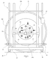
- system 1 is further provided with a tyre-removing frame 20 fixed articulatedly to the trolley 3 by an articulated system 23.
- the articulated system 23 is a pair of hinged arms 23a, 23b controlled by a manoeuvring actuator.
- the articulated system 23 enables the frame 20 to be neared to the wheel 100 in order that the wheel 100 can be raised once removed from the vehicle.
- the frame 20 is provided with a base 21 from which a pair of fixed lateral uprights 22 rise, located opposite one another, one of which being hinged, by the articulated system 23, to a free end of the trolley 3 in proximity of the self-centring group 5 of the tyre-removing device 2.
- Two vertically-slidable cross-bars are mounted to the pair of uprights 22, respectively a lower crossbar 26a and a higher crossbar 26b.
- Two horizontally-slidable rollers 24 are mounted at opposite ends of the lower crossbar 26a, which rollers 24 can be arranged at sides of the wheel 100 to be removed and having axes which are parallel to an axis of the wheel 100 in order to support the wheel 100.
- a hook 25 is hinged to the centre of the supper crossbar 26b, which hook 25 grips the upper portion of the wheel 100, in order to prevent the wheel 100 from tipping over once removed from the vehicle.
- the base 21 can be provided with wheels 30 which facilitate transport of the frame 20 on the ground.
- the frame 20 is further provided with a positioning structure.
- the positioning structure comprises a pair of vertical guides 27 arranged parallel to and internally of the uprights 22 of the frame 20 and fixed to the base 21 of the frame 20.
- a transversal bar 28 is slidably mounted on the guides 27, on which a screwing/unscrewing device 29 is free to slide horizontally.
- This configuration enables operating with greater precision.
- the operator can correctly position the screwing/unscrewing device 29 before the bolt 101 simply by sliding the screwing/unscrewing device 29 on the bar 28 and/or sliding the bar 28 on the guides 27.
- This configuration effectively prevents transmission of torque from the screwing/unscrewing device 29 to the user, which torque is typically present during the first unscrewing stage of each bolt 101, in particular when dealing with lorry wheel bolts,
- the screwing/unscrewing device 29 is provided with a sensor for enabling screwing-up of the bolts 101 during the wheel 100 remounting stage after tyre repair, with a predetermined tightening force.
- the tyre-removing device can be removed from the trolley 3 and located on a special platform, fixed to the ground, should there be particular applicational needs demanding this.
- the autonomous system equipped for replacement of tyres of the present invention satisfies the needs and obviates the drawbacks mentioned in the introductory part of the present description, with reference to the prior art.
- the system is easily transportable thanks to the wheels bearing it, one of which is powered.
- the use of the frame for removing the wheel means that the removal operation is done automatically and with extreme simplicity.
Landscapes
- Engineering & Computer Science (AREA)
- Mechanical Engineering (AREA)
- Tires In General (AREA)
- Automatic Assembly (AREA)
- Vehicle Cleaning, Maintenance, Repair, Refitting, And Outriggers (AREA)
- Automobile Manufacture Line, Endless Track Vehicle, Trailer (AREA)
- Steering Control In Accordance With Driving Conditions (AREA)
- Vehicle Body Suspensions (AREA)
Claims (9)
- Ein autonomes System (1), ausgestattet zur Reifenersetzung (100), unterbringbar in einer Ladekammer eines Fahrzeugs, wobei das System (1) eine Vorrichtung zur Reifenentfernung (2) enthält, das vollständig auf einem beweglichen Rahmen (3) sitzt, ausgestattet mit Rädern (4), die Vorrichtung zur Reifenentfernung (2) wird von einem Motor (6) betätigt, der auf dem Rahmen (3) sitzt, gekennzeichnet durch die Tatsache, dass es außerdem einen Rahmen (20) für die Entfernung des Rads aufweist, wobei der besagte Rahmen mit einem Positionierungsystem für eine Anschraub- und Abschraubvorrichtung (29) ausgestattet ist.
- Das System von Anspruch 1, wobei der Motor (6) einen internen Verbrennungsmotor (6) umfasst.
- Das System von Anspruch 2, wobei der interne Verbrennungsmotor (6) an einen Generator (11) angeschlossen ist, wobei der Generator die Elektrik der Vorrichtung zur Reifenentfernung (2) speist und der Generator (11) auf dem Rahmen (3) sitzt.
- Das System (1) von Anspruch 3, wobei der Generator (11) über einen Akkumulator einen Elektromotor (10) speist, der zumindest eins der Räder (4) des Rahmens (3) antreibt.
- Das System von Anspruch 2, wobei der interne Verbrennungsmotor (6) über eine abnehmbare Kupplung (8) eine Welle eines Elektromotors (7) antreibt, der an einen Verdichter (9) angeschlossen ist, wobei der Elektromotor (7) und der Verdichter (9) auf dem beweglichen Rahmen (3) sitzen.
- Das System (1) von Anspruch 1, wobei der besagte Rahmen (20) für die Entfernung eines Rads mit einem Gelenk am beweglichen Rahmen (3) befestigt ist.
- Das System (1) von Anspruch 6, wobei der Rahmen (20) Räder (30) und Vorrichtungen (24, 25) zum Halten des Rads (100) aufweist.
- Das System (1) von Anspruch 7, wobei die Vorrichtungen zum Halten des Rads ein Paar Rollen (24) umfassen, die seitlich des zu entfernenden Rads (100) positioniert werden, wobei sich die Achsen der Rollen (24) parallel zu einer Achse des Rads (100) befinden, sowie einen Haken (25) zum Greifen zumindest eines Teils des Rads (100).
- Das System (1) von Anspruch 6, wobei der Rahmen (20) ein Positionierungssystem aufweist, das mit einer Anschraub- und Abschraubvorrichtung (29) ausgestattet ist, wobei das Positionierungssystem dazu dient, die Anschraub- und Abschraubvorrichtung (29) in einer bestimmten Position zu halten.
Applications Claiming Priority (1)
| Application Number | Priority Date | Filing Date | Title |
|---|---|---|---|
| IT000042A ITRE20060042A1 (it) | 2006-03-28 | 2006-03-28 | Sistema autonomo attrezzato per la sostituzione di pneumatici |
Publications (2)
| Publication Number | Publication Date |
|---|---|
| EP1839905A1 EP1839905A1 (de) | 2007-10-03 |
| EP1839905B1 true EP1839905B1 (de) | 2009-05-27 |
Family
ID=38229598
Family Applications (1)
| Application Number | Title | Priority Date | Filing Date |
|---|---|---|---|
| EP07101670A Not-in-force EP1839905B1 (de) | 2006-03-28 | 2007-02-02 | Autonomes System zum Reifenwechseln |
Country Status (4)
| Country | Link |
|---|---|
| EP (1) | EP1839905B1 (de) |
| AT (1) | ATE432177T1 (de) |
| DE (1) | DE602007001159D1 (de) |
| IT (1) | ITRE20060042A1 (de) |
Families Citing this family (2)
| Publication number | Priority date | Publication date | Assignee | Title |
|---|---|---|---|---|
| CN101148158B (zh) * | 2007-11-09 | 2010-08-11 | 朱戈宇 | 移动式轮胎更换系统 |
| CN104354548B (zh) * | 2014-10-31 | 2017-01-25 | 成都众易通科技有限公司 | 一种自动更换车胎的装置 |
Family Cites Families (3)
| Publication number | Priority date | Publication date | Assignee | Title |
|---|---|---|---|---|
| FR2764240B1 (fr) * | 1997-06-09 | 1999-11-05 | Mangin Jacques Celerier | Chariot manipulateur de roues pour maintenance de vehicules industriels, transports en commun, travaux publics, agricoles et materiels speciaux et militaires |
| US6237206B1 (en) * | 1998-03-12 | 2001-05-29 | Kiene Diesel Accessories, Inc. | Wheel pulling and transporting device |
| CA2480376C (en) * | 2003-09-04 | 2013-04-09 | Justoy Pty Ltd | Article handling apparatus |
-
2006
- 2006-03-28 IT IT000042A patent/ITRE20060042A1/it unknown
-
2007
- 2007-02-02 AT AT07101670T patent/ATE432177T1/de not_active IP Right Cessation
- 2007-02-02 EP EP07101670A patent/EP1839905B1/de not_active Not-in-force
- 2007-02-02 DE DE602007001159T patent/DE602007001159D1/de active Active
Also Published As
| Publication number | Publication date |
|---|---|
| DE602007001159D1 (de) | 2009-07-09 |
| EP1839905A1 (de) | 2007-10-03 |
| ITRE20060042A1 (it) | 2007-09-29 |
| ATE432177T1 (de) | 2009-06-15 |
Similar Documents
| Publication | Publication Date | Title |
|---|---|---|
| US4133572A (en) | Utility trailer | |
| US20080048161A1 (en) | Trailer hitch installation support | |
| CN201275985Y (zh) | 车轮拆卸安装装置 | |
| MX2014014916A (es) | Aparato de transporte y manejo del tambor de cable. | |
| CN203282964U (zh) | 车轮总成安装拆卸装置 | |
| CN105209271B (zh) | 用于安装/拆卸重型货车轮胎的板载设备 | |
| EP1839905B1 (de) | Autonomes System zum Reifenwechseln | |
| US7172083B1 (en) | Mobile hydraulic hoist | |
| CN211364149U (zh) | 车轮维护装置 | |
| CN111070981A (zh) | 自行走式折叠轮胎快换车 | |
| CN205525030U (zh) | 飞机牵引智能机器人 | |
| CN108860267B (zh) | 电力设备二次搬运平台工具 | |
| CN105416608A (zh) | 飞机牵引智能机器人 | |
| CN206394371U (zh) | 车载轮胎拆装机 | |
| JPH07117672A (ja) | 車輪ジャッキと運搬車の組合せ体 | |
| CN1313303C (zh) | 汽车横向转移装置 | |
| CN216684250U (zh) | 遥控全地形运输车 | |
| CA2936166A1 (en) | A multi-functional carriage | |
| CN102311067B (zh) | 可用于防滑的变形千斤顶 | |
| CN211468084U (zh) | 一种自行走式折叠轮胎快换车 | |
| CN205259670U (zh) | 一种车库停车专用平台 | |
| CN201300668Y (zh) | 汽车防滑装置 | |
| US20100166532A1 (en) | Apparatus for manipulating and recovering wheels | |
| CN210113141U (zh) | 公路救援运输车 | |
| CN112477510B (zh) | 车轮维护装置 |
Legal Events
| Date | Code | Title | Description |
|---|---|---|---|
| PUAI | Public reference made under article 153(3) epc to a published international application that has entered the european phase |
Free format text: ORIGINAL CODE: 0009012 |
|
| AK | Designated contracting states |
Kind code of ref document: A1 Designated state(s): AT BE BG CH CY CZ DE DK EE ES FI FR GB GR HU IE IS IT LI LT LU LV MC NL PL PT RO SE SI SK TR |
|
| AX | Request for extension of the european patent |
Extension state: AL BA HR MK YU |
|
| 17P | Request for examination filed |
Effective date: 20080319 |
|
| AKX | Designation fees paid |
Designated state(s): AT BE BG CH CY CZ DE DK EE ES FI FR GB GR HU IE IS IT LI LT LU LV MC NL PL PT RO SE SI SK TR |
|
| GRAP | Despatch of communication of intention to grant a patent |
Free format text: ORIGINAL CODE: EPIDOSNIGR1 |
|
| GRAS | Grant fee paid |
Free format text: ORIGINAL CODE: EPIDOSNIGR3 |
|
| GRAA | (expected) grant |
Free format text: ORIGINAL CODE: 0009210 |
|
| AK | Designated contracting states |
Kind code of ref document: B1 Designated state(s): AT BE BG CH CY CZ DE DK EE ES FI FR GB GR HU IE IS IT LI LT LU LV MC NL PL PT RO SE SI SK TR |
|
| REG | Reference to a national code |
Ref country code: GB Ref legal event code: FG4D |
|
| REG | Reference to a national code |
Ref country code: CH Ref legal event code: EP |
|
| REG | Reference to a national code |
Ref country code: IE Ref legal event code: FG4D |
|
| REF | Corresponds to: |
Ref document number: 602007001159 Country of ref document: DE Date of ref document: 20090709 Kind code of ref document: P |
|
| PG25 | Lapsed in a contracting state [announced via postgrant information from national office to epo] |
Ref country code: PT Free format text: LAPSE BECAUSE OF FAILURE TO SUBMIT A TRANSLATION OF THE DESCRIPTION OR TO PAY THE FEE WITHIN THE PRESCRIBED TIME-LIMIT Effective date: 20090927 Ref country code: LT Free format text: LAPSE BECAUSE OF FAILURE TO SUBMIT A TRANSLATION OF THE DESCRIPTION OR TO PAY THE FEE WITHIN THE PRESCRIBED TIME-LIMIT Effective date: 20090527 Ref country code: AT Free format text: LAPSE BECAUSE OF FAILURE TO SUBMIT A TRANSLATION OF THE DESCRIPTION OR TO PAY THE FEE WITHIN THE PRESCRIBED TIME-LIMIT Effective date: 20090527 Ref country code: FI Free format text: LAPSE BECAUSE OF FAILURE TO SUBMIT A TRANSLATION OF THE DESCRIPTION OR TO PAY THE FEE WITHIN THE PRESCRIBED TIME-LIMIT Effective date: 20090527 |
|
| NLV1 | Nl: lapsed or annulled due to failure to fulfill the requirements of art. 29p and 29m of the patents act | ||
| PG25 | Lapsed in a contracting state [announced via postgrant information from national office to epo] |
Ref country code: PL Free format text: LAPSE BECAUSE OF FAILURE TO SUBMIT A TRANSLATION OF THE DESCRIPTION OR TO PAY THE FEE WITHIN THE PRESCRIBED TIME-LIMIT Effective date: 20090527 Ref country code: SI Free format text: LAPSE BECAUSE OF FAILURE TO SUBMIT A TRANSLATION OF THE DESCRIPTION OR TO PAY THE FEE WITHIN THE PRESCRIBED TIME-LIMIT Effective date: 20090527 Ref country code: LV Free format text: LAPSE BECAUSE OF FAILURE TO SUBMIT A TRANSLATION OF THE DESCRIPTION OR TO PAY THE FEE WITHIN THE PRESCRIBED TIME-LIMIT Effective date: 20090527 Ref country code: IS Free format text: LAPSE BECAUSE OF FAILURE TO SUBMIT A TRANSLATION OF THE DESCRIPTION OR TO PAY THE FEE WITHIN THE PRESCRIBED TIME-LIMIT Effective date: 20090927 Ref country code: SE Free format text: LAPSE BECAUSE OF FAILURE TO SUBMIT A TRANSLATION OF THE DESCRIPTION OR TO PAY THE FEE WITHIN THE PRESCRIBED TIME-LIMIT Effective date: 20090827 Ref country code: NL Free format text: LAPSE BECAUSE OF FAILURE TO SUBMIT A TRANSLATION OF THE DESCRIPTION OR TO PAY THE FEE WITHIN THE PRESCRIBED TIME-LIMIT Effective date: 20090527 |
|
| PG25 | Lapsed in a contracting state [announced via postgrant information from national office to epo] |
Ref country code: RO Free format text: LAPSE BECAUSE OF FAILURE TO SUBMIT A TRANSLATION OF THE DESCRIPTION OR TO PAY THE FEE WITHIN THE PRESCRIBED TIME-LIMIT Effective date: 20090527 Ref country code: DK Free format text: LAPSE BECAUSE OF FAILURE TO SUBMIT A TRANSLATION OF THE DESCRIPTION OR TO PAY THE FEE WITHIN THE PRESCRIBED TIME-LIMIT Effective date: 20090527 Ref country code: CZ Free format text: LAPSE BECAUSE OF FAILURE TO SUBMIT A TRANSLATION OF THE DESCRIPTION OR TO PAY THE FEE WITHIN THE PRESCRIBED TIME-LIMIT Effective date: 20090527 Ref country code: EE Free format text: LAPSE BECAUSE OF FAILURE TO SUBMIT A TRANSLATION OF THE DESCRIPTION OR TO PAY THE FEE WITHIN THE PRESCRIBED TIME-LIMIT Effective date: 20090527 Ref country code: ES Free format text: LAPSE BECAUSE OF FAILURE TO SUBMIT A TRANSLATION OF THE DESCRIPTION OR TO PAY THE FEE WITHIN THE PRESCRIBED TIME-LIMIT Effective date: 20090907 |
|
| PG25 | Lapsed in a contracting state [announced via postgrant information from national office to epo] |
Ref country code: BE Free format text: LAPSE BECAUSE OF FAILURE TO SUBMIT A TRANSLATION OF THE DESCRIPTION OR TO PAY THE FEE WITHIN THE PRESCRIBED TIME-LIMIT Effective date: 20090527 Ref country code: SK Free format text: LAPSE BECAUSE OF FAILURE TO SUBMIT A TRANSLATION OF THE DESCRIPTION OR TO PAY THE FEE WITHIN THE PRESCRIBED TIME-LIMIT Effective date: 20090527 |
|
| PG25 | Lapsed in a contracting state [announced via postgrant information from national office to epo] |
Ref country code: BG Free format text: LAPSE BECAUSE OF FAILURE TO SUBMIT A TRANSLATION OF THE DESCRIPTION OR TO PAY THE FEE WITHIN THE PRESCRIBED TIME-LIMIT Effective date: 20090827 |
|
| PLBE | No opposition filed within time limit |
Free format text: ORIGINAL CODE: 0009261 |
|
| STAA | Information on the status of an ep patent application or granted ep patent |
Free format text: STATUS: NO OPPOSITION FILED WITHIN TIME LIMIT |
|
| 26N | No opposition filed |
Effective date: 20100302 |
|
| PG25 | Lapsed in a contracting state [announced via postgrant information from national office to epo] |
Ref country code: MC Free format text: LAPSE BECAUSE OF NON-PAYMENT OF DUE FEES Effective date: 20100301 Ref country code: GR Free format text: LAPSE BECAUSE OF FAILURE TO SUBMIT A TRANSLATION OF THE DESCRIPTION OR TO PAY THE FEE WITHIN THE PRESCRIBED TIME-LIMIT Effective date: 20090828 |
|
| PG25 | Lapsed in a contracting state [announced via postgrant information from national office to epo] |
Ref country code: IE Free format text: LAPSE BECAUSE OF NON-PAYMENT OF DUE FEES Effective date: 20100202 |
|
| REG | Reference to a national code |
Ref country code: CH Ref legal event code: PL |
|
| PG25 | Lapsed in a contracting state [announced via postgrant information from national office to epo] |
Ref country code: LI Free format text: LAPSE BECAUSE OF NON-PAYMENT OF DUE FEES Effective date: 20110228 Ref country code: CH Free format text: LAPSE BECAUSE OF NON-PAYMENT OF DUE FEES Effective date: 20110228 |
|
| PGFP | Annual fee paid to national office [announced via postgrant information from national office to epo] |
Ref country code: FR Payment date: 20120307 Year of fee payment: 6 |
|
| PGFP | Annual fee paid to national office [announced via postgrant information from national office to epo] |
Ref country code: DE Payment date: 20120204 Year of fee payment: 6 |
|
| PGFP | Annual fee paid to national office [announced via postgrant information from national office to epo] |
Ref country code: GB Payment date: 20120216 Year of fee payment: 6 |
|
| PG25 | Lapsed in a contracting state [announced via postgrant information from national office to epo] |
Ref country code: CY Free format text: LAPSE BECAUSE OF FAILURE TO SUBMIT A TRANSLATION OF THE DESCRIPTION OR TO PAY THE FEE WITHIN THE PRESCRIBED TIME-LIMIT Effective date: 20090527 |
|
| PG25 | Lapsed in a contracting state [announced via postgrant information from national office to epo] |
Ref country code: LU Free format text: LAPSE BECAUSE OF NON-PAYMENT OF DUE FEES Effective date: 20100202 Ref country code: HU Free format text: LAPSE BECAUSE OF FAILURE TO SUBMIT A TRANSLATION OF THE DESCRIPTION OR TO PAY THE FEE WITHIN THE PRESCRIBED TIME-LIMIT Effective date: 20091128 |
|
| PG25 | Lapsed in a contracting state [announced via postgrant information from national office to epo] |
Ref country code: TR Free format text: LAPSE BECAUSE OF FAILURE TO SUBMIT A TRANSLATION OF THE DESCRIPTION OR TO PAY THE FEE WITHIN THE PRESCRIBED TIME-LIMIT Effective date: 20090527 |
|
| GBPC | Gb: european patent ceased through non-payment of renewal fee |
Effective date: 20130202 |
|
| REG | Reference to a national code |
Ref country code: FR Ref legal event code: ST Effective date: 20131031 |
|
| REG | Reference to a national code |
Ref country code: DE Ref legal event code: R119 Ref document number: 602007001159 Country of ref document: DE Effective date: 20130903 |
|
| PG25 | Lapsed in a contracting state [announced via postgrant information from national office to epo] |
Ref country code: GB Free format text: LAPSE BECAUSE OF NON-PAYMENT OF DUE FEES Effective date: 20130202 Ref country code: DE Free format text: LAPSE BECAUSE OF NON-PAYMENT OF DUE FEES Effective date: 20130903 Ref country code: FR Free format text: LAPSE BECAUSE OF NON-PAYMENT OF DUE FEES Effective date: 20130228 |
|
| PGFP | Annual fee paid to national office [announced via postgrant information from national office to epo] |
Ref country code: IT Payment date: 20181128 Year of fee payment: 13 |
|
| PG25 | Lapsed in a contracting state [announced via postgrant information from national office to epo] |
Ref country code: IT Free format text: LAPSE BECAUSE OF NON-PAYMENT OF DUE FEES Effective date: 20200202 |