EP1840219B1 - Système et procédé de distinguer une solution de contrôle d'un échantillon physiologique de sang - Google Patents
Système et procédé de distinguer une solution de contrôle d'un échantillon physiologique de sang Download PDFInfo
- Publication number
- EP1840219B1 EP1840219B1 EP07251388.0A EP07251388A EP1840219B1 EP 1840219 B1 EP1840219 B1 EP 1840219B1 EP 07251388 A EP07251388 A EP 07251388A EP 1840219 B1 EP1840219 B1 EP 1840219B1
- Authority
- EP
- European Patent Office
- Prior art keywords
- sample
- test
- current
- potential
- control solution
- Prior art date
- Legal status (The legal status is an assumption and is not a legal conclusion. Google has not performed a legal analysis and makes no representation as to the accuracy of the status listed.)
- Not-in-force
Links
- 210000004369 blood Anatomy 0.000 title claims description 85
- 239000008280 blood Substances 0.000 title claims description 85
- 238000000034 method Methods 0.000 title claims description 46
- 238000012360 testing method Methods 0.000 claims description 173
- 239000000523 sample Substances 0.000 claims description 92
- 238000006243 chemical reaction Methods 0.000 claims description 69
- 230000001052 transient effect Effects 0.000 claims description 43
- 239000003153 chemical reaction reagent Substances 0.000 claims description 19
- 239000012491 analyte Substances 0.000 claims description 17
- 239000003963 antioxidant agent Substances 0.000 claims description 4
- 239000013068 control sample Substances 0.000 claims description 4
- 238000013500 data storage Methods 0.000 claims description 2
- 230000003078 antioxidant effect Effects 0.000 claims 2
- 230000013011 mating Effects 0.000 claims 1
- 239000000243 solution Substances 0.000 description 79
- WQZGKKKJIJFFOK-GASJEMHNSA-N Glucose Natural products OC[C@H]1OC(O)[C@H](O)[C@@H](O)[C@@H]1O WQZGKKKJIJFFOK-GASJEMHNSA-N 0.000 description 47
- WQZGKKKJIJFFOK-VFUOTHLCSA-N beta-D-glucose Chemical compound OC[C@H]1O[C@@H](O)[C@H](O)[C@@H](O)[C@@H]1O WQZGKKKJIJFFOK-VFUOTHLCSA-N 0.000 description 47
- 239000008103 glucose Substances 0.000 description 45
- 239000012530 fluid Substances 0.000 description 32
- 108010050375 Glucose 1-Dehydrogenase Proteins 0.000 description 19
- 238000005534 hematocrit Methods 0.000 description 18
- 230000002829 reductive effect Effects 0.000 description 11
- 239000000758 substrate Substances 0.000 description 10
- 230000006870 function Effects 0.000 description 8
- KDLHZDBZIXYQEI-UHFFFAOYSA-N Palladium Chemical compound [Pd] KDLHZDBZIXYQEI-UHFFFAOYSA-N 0.000 description 6
- 210000004027 cell Anatomy 0.000 description 5
- -1 for example Substances 0.000 description 5
- 230000000670 limiting effect Effects 0.000 description 5
- 238000005259 measurement Methods 0.000 description 5
- 230000003647 oxidation Effects 0.000 description 5
- 238000007254 oxidation reaction Methods 0.000 description 5
- 230000008569 process Effects 0.000 description 5
- WXTMDXOMEHJXQO-UHFFFAOYSA-N 2,5-dihydroxybenzoic acid Chemical compound OC(=O)C1=CC(O)=CC=C1O WXTMDXOMEHJXQO-UHFFFAOYSA-N 0.000 description 4
- 238000003556 assay Methods 0.000 description 4
- 238000004364 calculation method Methods 0.000 description 4
- HNEGQIOMVPPMNR-IHWYPQMZSA-N citraconic acid Chemical compound OC(=O)C(/C)=C\C(O)=O HNEGQIOMVPPMNR-IHWYPQMZSA-N 0.000 description 4
- YAGKRVSRTSUGEY-UHFFFAOYSA-N ferricyanide Chemical compound [Fe+3].N#[C-].N#[C-].N#[C-].N#[C-].N#[C-].N#[C-] YAGKRVSRTSUGEY-UHFFFAOYSA-N 0.000 description 4
- LXCFILQKKLGQFO-UHFFFAOYSA-N methylparaben Chemical compound COC(=O)C1=CC=C(O)C=C1 LXCFILQKKLGQFO-UHFFFAOYSA-N 0.000 description 4
- 239000012476 oxidizable substance Substances 0.000 description 4
- 125000006850 spacer group Chemical group 0.000 description 4
- 238000004422 calculation algorithm Methods 0.000 description 3
- 238000001514 detection method Methods 0.000 description 3
- 238000011161 development Methods 0.000 description 3
- 239000010432 diamond Substances 0.000 description 3
- PCHJSUWPFVWCPO-UHFFFAOYSA-N gold Chemical compound [Au] PCHJSUWPFVWCPO-UHFFFAOYSA-N 0.000 description 3
- 229910052737 gold Inorganic materials 0.000 description 3
- 239000010931 gold Substances 0.000 description 3
- 239000000203 mixture Substances 0.000 description 3
- 229910052763 palladium Inorganic materials 0.000 description 3
- 239000003755 preservative agent Substances 0.000 description 3
- 230000002335 preservative effect Effects 0.000 description 3
- MMXZSJMASHPLLR-UHFFFAOYSA-N pyrroloquinoline quinone Chemical compound C12=C(C(O)=O)C=C(C(O)=O)N=C2C(=O)C(=O)C2=C1NC(C(=O)O)=C2 MMXZSJMASHPLLR-UHFFFAOYSA-N 0.000 description 3
- 238000012552 review Methods 0.000 description 3
- 239000000126 substance Substances 0.000 description 3
- CIWBSHSKHKDKBQ-JLAZNSOCSA-N Ascorbic acid Chemical compound OC[C@H](O)[C@H]1OC(=O)C(O)=C1O CIWBSHSKHKDKBQ-JLAZNSOCSA-N 0.000 description 2
- 229920002307 Dextran Polymers 0.000 description 2
- 108090000790 Enzymes Proteins 0.000 description 2
- 102000004190 Enzymes Human genes 0.000 description 2
- 235000006708 antioxidants Nutrition 0.000 description 2
- 230000008901 benefit Effects 0.000 description 2
- 239000000872 buffer Substances 0.000 description 2
- 239000008364 bulk solution Substances 0.000 description 2
- 239000013626 chemical specie Substances 0.000 description 2
- HVYWMOMLDIMFJA-DPAQBDIFSA-N cholesterol Chemical compound C1C=C2C[C@@H](O)CC[C@]2(C)[C@@H]2[C@@H]1[C@@H]1CC[C@H]([C@H](C)CCCC(C)C)[C@@]1(C)CC2 HVYWMOMLDIMFJA-DPAQBDIFSA-N 0.000 description 2
- 229940018560 citraconate Drugs 0.000 description 2
- 229940018557 citraconic acid Drugs 0.000 description 2
- 150000001875 compounds Chemical class 0.000 description 2
- 239000004020 conductor Substances 0.000 description 2
- 239000008367 deionised water Substances 0.000 description 2
- 229910021641 deionized water Inorganic materials 0.000 description 2
- 238000009792 diffusion process Methods 0.000 description 2
- KCIDZIIHRGYJAE-YGFYJFDDSA-L dipotassium;[(2r,3r,4s,5r,6r)-3,4,5-trihydroxy-6-(hydroxymethyl)oxan-2-yl] phosphate Chemical compound [K+].[K+].OC[C@H]1O[C@H](OP([O-])([O-])=O)[C@H](O)[C@@H](O)[C@H]1O KCIDZIIHRGYJAE-YGFYJFDDSA-L 0.000 description 2
- 238000000840 electrochemical analysis Methods 0.000 description 2
- 229940088598 enzyme Drugs 0.000 description 2
- 210000003743 erythrocyte Anatomy 0.000 description 2
- KTWOOEGAPBSYNW-UHFFFAOYSA-N ferrocene Chemical compound [Fe+2].C=1C=C[CH-]C=1.C=1C=C[CH-]C=1 KTWOOEGAPBSYNW-UHFFFAOYSA-N 0.000 description 2
- 229960005219 gentisic acid Drugs 0.000 description 2
- 229910052738 indium Inorganic materials 0.000 description 2
- APFVFJFRJDLVQX-UHFFFAOYSA-N indium atom Chemical compound [In] APFVFJFRJDLVQX-UHFFFAOYSA-N 0.000 description 2
- 238000007726 management method Methods 0.000 description 2
- 239000000463 material Substances 0.000 description 2
- 235000010270 methyl p-hydroxybenzoate Nutrition 0.000 description 2
- 239000004292 methyl p-hydroxybenzoate Substances 0.000 description 2
- 229960002216 methylparaben Drugs 0.000 description 2
- BASFCYQUMIYNBI-UHFFFAOYSA-N platinum Chemical compound [Pt] BASFCYQUMIYNBI-UHFFFAOYSA-N 0.000 description 2
- 229920001983 poloxamer Polymers 0.000 description 2
- 238000007650 screen-printing Methods 0.000 description 2
- XOLBLPGZBRYERU-UHFFFAOYSA-N tin dioxide Chemical compound O=[Sn]=O XOLBLPGZBRYERU-UHFFFAOYSA-N 0.000 description 2
- 229910001887 tin oxide Inorganic materials 0.000 description 2
- XLYOFNOQVPJJNP-UHFFFAOYSA-N water Chemical compound O XLYOFNOQVPJJNP-UHFFFAOYSA-N 0.000 description 2
- WKMPTBDYDNUJLF-UHFFFAOYSA-N 2-fluoroadenine Chemical compound NC1=NC(F)=NC2=C1N=CN2 WKMPTBDYDNUJLF-UHFFFAOYSA-N 0.000 description 1
- BSYNRYMUTXBXSQ-UHFFFAOYSA-N Aspirin Chemical class CC(=O)OC1=CC=CC=C1C(O)=O BSYNRYMUTXBXSQ-UHFFFAOYSA-N 0.000 description 1
- 238000012935 Averaging Methods 0.000 description 1
- SGHZXLIDFTYFHQ-UHFFFAOYSA-L Brilliant Blue Chemical compound [Na+].[Na+].C=1C=C(C(=C2C=CC(C=C2)=[N+](CC)CC=2C=C(C=CC=2)S([O-])(=O)=O)C=2C(=CC=CC=2)S([O-])(=O)=O)C=CC=1N(CC)CC1=CC=CC(S([O-])(=O)=O)=C1 SGHZXLIDFTYFHQ-UHFFFAOYSA-L 0.000 description 1
- OKTJSMMVPCPJKN-UHFFFAOYSA-N Carbon Chemical compound [C] OKTJSMMVPCPJKN-UHFFFAOYSA-N 0.000 description 1
- RGHNJXZEOKUKBD-UHFFFAOYSA-N D-gluconic acid Natural products OCC(O)C(O)C(O)C(O)C(O)=O RGHNJXZEOKUKBD-UHFFFAOYSA-N 0.000 description 1
- RGHNJXZEOKUKBD-SQOUGZDYSA-N Gluconic acid Natural products OC[C@@H](O)[C@@H](O)[C@H](O)[C@@H](O)C(O)=O RGHNJXZEOKUKBD-SQOUGZDYSA-N 0.000 description 1
- 108010015776 Glucose oxidase Proteins 0.000 description 1
- 239000004366 Glucose oxidase Substances 0.000 description 1
- BAWFJGJZGIEFAR-NNYOXOHSSA-N NAD zwitterion Chemical compound NC(=O)C1=CC=C[N+]([C@H]2[C@@H]([C@H](O)[C@@H](COP([O-])(=O)OP(O)(=O)OC[C@@H]3[C@H]([C@@H](O)[C@@H](O3)N3C4=NC=NC(N)=C4N=C3)O)O2)O)=C1 BAWFJGJZGIEFAR-NNYOXOHSSA-N 0.000 description 1
- 239000004642 Polyimide Substances 0.000 description 1
- 239000004793 Polystyrene Substances 0.000 description 1
- BQCADISMDOOEFD-UHFFFAOYSA-N Silver Chemical compound [Ag] BQCADISMDOOEFD-UHFFFAOYSA-N 0.000 description 1
- LEHOTFFKMJEONL-UHFFFAOYSA-N Uric Acid Chemical compound N1C(=O)NC(=O)C2=C1NC(=O)N2 LEHOTFFKMJEONL-UHFFFAOYSA-N 0.000 description 1
- TVWHNULVHGKJHS-UHFFFAOYSA-N Uric acid Natural products N1C(=O)NC(=O)C2NC(=O)NC21 TVWHNULVHGKJHS-UHFFFAOYSA-N 0.000 description 1
- 238000010521 absorption reaction Methods 0.000 description 1
- 230000009471 action Effects 0.000 description 1
- 239000000853 adhesive Substances 0.000 description 1
- 230000001070 adhesive effect Effects 0.000 description 1
- 238000013459 approach Methods 0.000 description 1
- 239000007864 aqueous solution Substances 0.000 description 1
- 235000010323 ascorbic acid Nutrition 0.000 description 1
- 229960005070 ascorbic acid Drugs 0.000 description 1
- 239000011668 ascorbic acid Substances 0.000 description 1
- 230000002238 attenuated effect Effects 0.000 description 1
- 239000004161 brilliant blue FCF Substances 0.000 description 1
- 235000012745 brilliant blue FCF Nutrition 0.000 description 1
- 239000007853 buffer solution Substances 0.000 description 1
- 229910052799 carbon Inorganic materials 0.000 description 1
- 239000000919 ceramic Substances 0.000 description 1
- 239000003795 chemical substances by application Substances 0.000 description 1
- 235000012000 cholesterol Nutrition 0.000 description 1
- 239000011248 coating agent Substances 0.000 description 1
- 238000000576 coating method Methods 0.000 description 1
- 238000004891 communication Methods 0.000 description 1
- 238000012937 correction Methods 0.000 description 1
- 238000003869 coulometry Methods 0.000 description 1
- 230000001351 cycling effect Effects 0.000 description 1
- 238000009795 derivation Methods 0.000 description 1
- 206010012601 diabetes mellitus Diseases 0.000 description 1
- 238000003745 diagnosis Methods 0.000 description 1
- 201000010099 disease Diseases 0.000 description 1
- 208000037265 diseases, disorders, signs and symptoms Diseases 0.000 description 1
- 238000004090 dissolution Methods 0.000 description 1
- 230000002526 effect on cardiovascular system Effects 0.000 description 1
- 230000005518 electrochemistry Effects 0.000 description 1
- 238000007772 electroless plating Methods 0.000 description 1
- 238000002474 experimental method Methods 0.000 description 1
- 230000004907 flux Effects 0.000 description 1
- 238000009472 formulation Methods 0.000 description 1
- 239000011521 glass Substances 0.000 description 1
- 235000012208 gluconic acid Nutrition 0.000 description 1
- 239000000174 gluconic acid Substances 0.000 description 1
- 229940116332 glucose oxidase Drugs 0.000 description 1
- 235000019420 glucose oxidase Nutrition 0.000 description 1
- 125000002791 glucosyl group Chemical group C1([C@H](O)[C@@H](O)[C@H](O)[C@H](O1)CO)* 0.000 description 1
- 238000002347 injection Methods 0.000 description 1
- 239000007924 injection Substances 0.000 description 1
- 238000007641 inkjet printing Methods 0.000 description 1
- 239000011810 insulating material Substances 0.000 description 1
- 230000003993 interaction Effects 0.000 description 1
- 229910052741 iridium Inorganic materials 0.000 description 1
- GKOZUEZYRPOHIO-UHFFFAOYSA-N iridium atom Chemical compound [Ir] GKOZUEZYRPOHIO-UHFFFAOYSA-N 0.000 description 1
- 238000012417 linear regression Methods 0.000 description 1
- 239000007788 liquid Substances 0.000 description 1
- 238000004519 manufacturing process Methods 0.000 description 1
- 238000012544 monitoring process Methods 0.000 description 1
- 229950006238 nadide Drugs 0.000 description 1
- 229930027945 nicotinamide-adenine dinucleotide Natural products 0.000 description 1
- 229910052762 osmium Inorganic materials 0.000 description 1
- 230000036961 partial effect Effects 0.000 description 1
- 239000004033 plastic Substances 0.000 description 1
- 229920003023 plastic Polymers 0.000 description 1
- 229910052697 platinum Inorganic materials 0.000 description 1
- 239000004417 polycarbonate Substances 0.000 description 1
- 229920000515 polycarbonate Polymers 0.000 description 1
- 229920000139 polyethylene terephthalate Polymers 0.000 description 1
- 229920005644 polyethylene terephthalate glycol copolymer Polymers 0.000 description 1
- 229920001721 polyimide Polymers 0.000 description 1
- 229920002223 polystyrene Polymers 0.000 description 1
- 238000002360 preparation method Methods 0.000 description 1
- 150000004059 quinone derivatives Chemical class 0.000 description 1
- 230000001172 regenerating effect Effects 0.000 description 1
- 238000005204 segregation Methods 0.000 description 1
- 238000000926 separation method Methods 0.000 description 1
- 239000010703 silicon Substances 0.000 description 1
- 229910052710 silicon Inorganic materials 0.000 description 1
- 229910052709 silver Inorganic materials 0.000 description 1
- 239000004332 silver Substances 0.000 description 1
- 239000002904 solvent Substances 0.000 description 1
- 238000004544 sputter deposition Methods 0.000 description 1
- 238000007619 statistical method Methods 0.000 description 1
- 239000012085 test solution Substances 0.000 description 1
- 229940116269 uric acid Drugs 0.000 description 1
- 239000004034 viscosity adjusting agent Substances 0.000 description 1
Images




Classifications
-
- G—PHYSICS
- G01—MEASURING; TESTING
- G01N—INVESTIGATING OR ANALYSING MATERIALS BY DETERMINING THEIR CHEMICAL OR PHYSICAL PROPERTIES
- G01N27/00—Investigating or analysing materials by the use of electric, electrochemical, or magnetic means
- G01N27/26—Investigating or analysing materials by the use of electric, electrochemical, or magnetic means by investigating electrochemical variables; by using electrolysis or electrophoresis
- G01N27/28—Electrolytic cell components
- G01N27/30—Electrodes, e.g. test electrodes; Half-cells
- G01N27/327—Biochemical electrodes, e.g. electrical or mechanical details for in vitro measurements
- G01N27/3271—Amperometric enzyme electrodes for analytes in body fluids, e.g. glucose in blood
-
- C—CHEMISTRY; METALLURGY
- C12—BIOCHEMISTRY; BEER; SPIRITS; WINE; VINEGAR; MICROBIOLOGY; ENZYMOLOGY; MUTATION OR GENETIC ENGINEERING
- C12Q—MEASURING OR TESTING PROCESSES INVOLVING ENZYMES, NUCLEIC ACIDS OR MICROORGANISMS; COMPOSITIONS OR TEST PAPERS THEREFOR; PROCESSES OF PREPARING SUCH COMPOSITIONS; CONDITION-RESPONSIVE CONTROL IN MICROBIOLOGICAL OR ENZYMOLOGICAL PROCESSES
- C12Q1/00—Measuring or testing processes involving enzymes, nucleic acids or microorganisms; Compositions therefor; Processes of preparing such compositions
- C12Q1/001—Enzyme electrodes
-
- C—CHEMISTRY; METALLURGY
- C12—BIOCHEMISTRY; BEER; SPIRITS; WINE; VINEGAR; MICROBIOLOGY; ENZYMOLOGY; MUTATION OR GENETIC ENGINEERING
- C12Q—MEASURING OR TESTING PROCESSES INVOLVING ENZYMES, NUCLEIC ACIDS OR MICROORGANISMS; COMPOSITIONS OR TEST PAPERS THEREFOR; PROCESSES OF PREPARING SUCH COMPOSITIONS; CONDITION-RESPONSIVE CONTROL IN MICROBIOLOGICAL OR ENZYMOLOGICAL PROCESSES
- C12Q1/00—Measuring or testing processes involving enzymes, nucleic acids or microorganisms; Compositions therefor; Processes of preparing such compositions
- C12Q1/001—Enzyme electrodes
- C12Q1/005—Enzyme electrodes involving specific analytes or enzymes
- C12Q1/006—Enzyme electrodes involving specific analytes or enzymes for glucose
-
- G—PHYSICS
- G01—MEASURING; TESTING
- G01N—INVESTIGATING OR ANALYSING MATERIALS BY DETERMINING THEIR CHEMICAL OR PHYSICAL PROPERTIES
- G01N27/00—Investigating or analysing materials by the use of electric, electrochemical, or magnetic means
- G01N27/26—Investigating or analysing materials by the use of electric, electrochemical, or magnetic means by investigating electrochemical variables; by using electrolysis or electrophoresis
- G01N27/28—Electrolytic cell components
- G01N27/30—Electrodes, e.g. test electrodes; Half-cells
- G01N27/327—Biochemical electrodes, e.g. electrical or mechanical details for in vitro measurements
- G01N27/3271—Amperometric enzyme electrodes for analytes in body fluids, e.g. glucose in blood
- G01N27/3274—Corrective measures, e.g. error detection, compensation for temperature or hematocrit, calibration
Definitions
- Analyte concentration determination in physiological fluids is of ever increasing importance to today's society.
- Such assays find use in a variety of applications and settings, including clinical laboratory testing, home testing, etc., where the results of such testing play a prominent role in the diagnosis and management of a variety of disease conditions.
- Analytes of interest include glucose for diabetes management, cholesterol for monitoring cardiovascular conditions, and the like.
- a common method for analyte concentration determination assays is based on electrochemistry.
- an aqueous liquid sample is placed into a sample reaction chamber in an electrochemical cell made up of at least two electrodes, i.e., a reference and working electrode, where the electrodes have an impedance which renders them suitable for amperometric or coulometric measurement.
- the component to be analyzed is allowed to react directly with an electrode, or directly or indirectly with a reagent to form an oxidizable (or reducible) substance in an amount corresponding to the concentration of the component to be analyzed, i.e., analyte.
- the quantity of the oxidizable (or reducible) substance present is then estimated electrochemically and related to the amount of analyte present in the initial sample.
- An automated device e.g., an electrochemical test meter is typically employed for determining the concentration of the analyte in the sample.
- Many test meters advantageously allow for an analyte concentration, and usually a plurality of analyte concentrations, to be stored in the memory of the meter. This feature provides the user with the ability to review analyte concentration levels over a period of time, often times as an average of previously collected analyte levels, where such averaging is performed according to an algorithm associated with the meter.
- control fluids also referred to as control solutions
- control solutions are generally aqueous solutions having a known concentration of glucose.
- the user can perform a test with the control solution and compare the displayed results with the known concentration to determine if the system is functioning properly.
- the glucose concentration level of the control fluid is stored in the memory of the meter.
- the results may be skewed to the concentration of the control fluid analyte level.
- the present invention generally provides systems and methods for distinguishing between a control solution and a blood sample, as defined in method claim 1 and system claim 13.
- the subject systems and methods are suitable for use in the determination of a wide variety of analytes in a wide variety of samples, and are particularly suited for use in the determination of analytes in whole blood or derivatives thereof, where an analyte of particular interest is glucose.
- the disclosure provides methods for a test meter to determine whether control solution or blood has been applied to a test strip.
- at least two characteristics are used to distinguish between a blood sample and a control solution.
- Described herein are structures of an exemplary test strip which can be used with the methods and systems disclosed herein.
- methods for calculating a discrimination criterion based upon at least two characteristics.
- systems for distinguishing between a blood sample and a control solution are described herein.
- an electrochemical cell can be in the form of a test strip.
- the test strip includes two opposing electrodes separated by a thin spacer layer, where these components define a sample reaction chamber or zone in which is located a reagent layer.
- test strips including, for example, test strips with co-planar electrodes could also be used with the methods described herein.
- Test strip 62 can include an elongate body extending from a proximal end 80 to a distal end 82, and having lateral edges 56, 58.
- the proximal portion of body 59 can include a reaction chamber 61 having electrodes and a reagent, while the distal portion of test strip body 59 can include features adapted for electrically communicating with a test meter.
- Physiological fluid or control solution can be delivered to reaction chamber 61 and electrochemically analyzed.
- Test strip 62 comprises a first electrode layer 66 and a second electrode layer 64, with a spacer layer 60 positioned therebetween.
- the first electrode layer 66 can provide a first electrode 166 and a first connection track 76 for electrically connecting the first electrode 166 to a first electrical contact 67.
- second electrode layer 64 can provide a second electrode 164 and a second connection track for electrically connecting the second electrode 164 with a second electrical contact 63.
- Sample reaction chamber 61 is defined by first electrode 166, second electrode 164, and spacer 60 as shown in Figures 1A to 4B .
- first electrode 166 and second electrode 164 define, respectively, the bottom and top of sample reaction chamber 61.
- a cutout area 68 of spacer 60 can define the side walls of sample reaction chamber 61.
- reaction chamber 61 can further include ports 70 that provide a sample inlet and/or a vent.
- one of the ports can provide a fluid sample ingress and the other port can act as a vent.
- Reaction chamber 61 can have a small volume, ranging from about 0.1 microliters to 5 microliters, preferably about 0.2 microliters to about 3 microliters, and more preferably about 0.3 microliters to about 1 microliter.
- To provide the small sample volume cutout 68 can have an area ranging from about 0.01 cm 2 to about 0.2 cm 2 , preferably about 0.02 cm 2 to about 0.15 cm 2 , and more preferably about 0.03 cm 2 to about 0.08 cm 2 .
- first and second electrode 166, 164 can be spaced in the range of about 1 micron to 500 microns, preferably between about 10 microns and 400 microns, and more preferably between about 40 microns and 200 microns. The close spacing of the electrodes can also allow redox cycling to occur, where oxidized mediator generated at first electrode 166, can diffuse to second electrode 164 to become reduced, and subsequently diffuse back to first electrode 166 to become oxidized again.
- first electrical contact 67 can be used to establish an electrical connection to a test meter.
- Second electrical contact 63 can be accessed by the test meter through U-shaped notch 65 as illustrated in Figure 2 .
- test strip 62 can include a variety of alternative electrical contact configured for electrically connecting to a test meter.
- U.S. Patent No. 6,379,513 discloses an electrochemical cell connection means.
- first electrode layer 66 and/or second electrode layer 64 can be a conductive material formed from materials such as gold, palladium, carbon, silver, platinum, tin oxide, iridium, indium, and combinations thereof (e.g., indium doped tin oxide).
- the electrodes can be formed by disposing a conductive material onto an insulating sheet (not shown) by a sputtering, electroless plating, or a screen printing process.
- Second electrode layer 64 can be a sputtered gold electrode and first electrode layer 66 can be a sputtered palladium electrode.
- Suitable materials that can be employed as spacing layer 60 include the variety of insulating materials, such as, for example, plastics (e.g., PET, PETG, polyimide, polycarbonate, polystyrene), silicon, ceramic, glass, adhesives, and combinations thereof.
- plastics e.g., PET, PETG, polyimide, polycarbonate, polystyrene
- silicon e.g., silicon, ceramic, glass, adhesives, and combinations thereof.
- Reagent layer 72 can be disposed within reaction chamber 61 using a process such as slot coating, dispensing from the end of a tube, ink jetting, and screen printing. Such processes are described, for example, in the following U.S. Patent Nos. 6,749,887 ; 6,869,411 ; 6,676,995 ; and 6,830,93 4 .
- Reagent layer 72 includes at least a mediator and an enzyme and is deposited onto first electrode 166.
- mediators include ferricyanide, ferrocene, ferrocene derivatives, osmium bipyridyl complexes, and quinone derivatives.
- suitable enzymes include glucose oxidase, glucose dehydrogenase (GDH) based on pyrroloquinoline quinone (PQQ) co-factor, GDH based on nicotinamide adenine dinucleotide co-factor, and FAD-based GDH [E.C.1.1.99.10].
- GDH glucose dehydrogenase
- PQQ pyrroloquinoline quinone
- GDH based on nicotinamide adenine dinucleotide co-factor
- FAD-based GDH FAD-based GDH
- first electrode 166 or second electrode 164 can perform the function of a working electrode which oxidizes or reduces a limiting amount of mediator depending on the polarity of the applied test potential of the test meter. For example, if the current limiting species is a reduced mediator, then it can be oxidized at first electrode 166 as long as a sufficiently positive potential was applied with respect to second electrode 164. In such a situation, first electrode 166 performs the function of the working electrode and second electrode 164 performs the function of a counter/reference electrode. It should be noted that unless otherwise stated for test strip 62, all potentials applied by test meter 100 will hereinafter be stated with respect to second electrode 164.
- second electrode 164 performs the function of the working electrode and first electrode 166 performs the function of the counter/reference electrode.
- a first step in the subject methods can include introducing a quantity of the fluid sample of interest into test strip 62 which includes first electrode 166, second electrode 164 and a reagent layer 72.
- the fluid sample can be whole blood or a derivative or fraction thereof, or control solution.
- the fluid sample e.g., blood
- port 70 and /or reaction chamber 61 are adapted such that capillary action causes the fluid sample to fill sample reaction chamber 61.
- Figure 5 provides a simplified schematic showing a test meter 100 interfacing with first electrical contact 67 and second electrical contact 63, which are in electrical communication with first electrode 166 and second electrode 164, respectively, of test strip 62.
- Test meter 100 is adapted to electrically connect to first electrode 166 and second electrode 164, via first electrical contact 67 and second electrical contact 63, respectively (as shown in Figures 2 and 5 ).
- the variety of known test meters can be used with the method described herein.
- the test meter system includes at least a processor for performing calculations related to discriminating between blood and a control sample and data storage.
- electrical contact 67 can include two prongs denoted as 67a and 67b.
- Test meter 100 can separately connect to prongs 67a and 67b, such that when test meter 100 interfaces with test strip 62 a circuit is completed.
- Test meter 100 can measure the resistance or electrical continuity between prongs 67a and 67b to determine whether test strip 62 is electrically connected to test meter 100.
- test meter 100 can use a variety of sensors and circuits to determine when test strip 62 is properly positioned with respect to test meter 100.
- Test meter 100 can apply a test potential and/or a current between first electrical contact 67 and second electrical contact 63. Once test meter 100 recognizes that strip 62 has been inserted, test meter 100 turns on and initiates a fluid detection mode. The fluid detection mode can cause test meter 100 to apply a constant current of 1 microampere between first electrode 166 and second electrode 164. Because test strip 62 is initially dry, test meter 100 measures a maximum voltage, which is limited by the hardware within test meter 100. However, once a user doses a fluid sample onto inlet 70, this causes sample reaction chamber 61 to become filled.
- test meter 100 When the fluid sample bridges the gap between first electrode 166 and second electrode 164, test meter 100 will measure a decrease in measured voltage (e.g., as described in U.S. Patent No. 6,193, 873 ) which is below a predetermined threshold causing test meter 100 to automatically initiate the glucose test.
- measured voltage e.g., as described in U.S. Patent No. 6,193, 873
- the measured voltage may decrease below a predetermined threshold when only a fraction of sample reaction chamber 61 has been filled.
- a method of automatically recognizing that a fluid was applied does not necessarily indicate that sample reaction chamber 61 has been completely filled, but can only confirm a presence of some fluid in sample reaction chamber 61.
- test meter 100 determines that a fluid has been applied to test strip 62, a short, but finite amount of time may still be required to allow the fluid to completely fill sample reaction chamber 61.
- test meter 100 can perform a glucose test by applying a plurality of open-circuit potentials and a plurality of test potentials to the test strip 62 for prescribed intervals as shown in Figure 6 .
- a glucose test time interval T G represents an amount of time to perform the glucose test (but not necessarily all the calculations associated with the glucose test) where glucose test time interval T G can include a first open-circuit time interval T OCI , a first test potential time interval T 1 , a second open-circuit time interval T OC2 , a second test potential time interval T 2 , and a third test potential time interval T 3 .
- Glucose test time interval T G can range from about 1 second to about 5 seconds. While two open-circuit time intervals and three test potential time intervals are described, one skilled in the art will appreciate that the glucose test time interval can comprise different numbers of open-circuit and test potential time intervals. For example, the glucose test time interval could include a single open-circuit time interval and/or only two test potential time intervals.
- test meter 100 switches to a first open-circuit for a first open-circuit potential time interval T OC1 , which in the illustrated embodiment is about 0.2 seconds.
- First open-circuit time interval T OC1 can be in the range of about 0.05 seconds to about 2 seconds and preferably between about 0.1 seconds to about 1.0 seconds, and most preferably between about 0.15 seconds to about 0.6 seconds.
- sample reaction chamber 61 takes about 0.1 seconds to about 0.5 seconds to completely fill with blood.
- sample reaction chamber 61 takes about 0.2 seconds or less to completely fill with control solution, where the control solution is formulated to have a viscosity of about 1 to about 3 centipoise.
- blood samples can vary in their make-up and/or composition.
- high hematocrit blood samples are more viscous than low hematocrit blood samples, therefore higher hematocrit blood samples require additional time to fill compared with lower hematocrit blood samples.
- blood sample filling time can vary depending on a variety of factors.
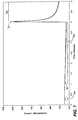
- test meter 100 After applying the first open-circuit potential, test meter 100 applies a first test potential E 1 between first electrode 166 and second electrode 164 (e.g., -0.3 Volts in Figure 6 ), for a first test potential time interval T 1 (e.g., 0.15 seconds in Figure 6 ). Test meter 100 measures the resulting first current transient, which can be referred to as i a ( t ) as shown in Figure 7 .
- First test potential time interval T 1 can be in the range of about 0.05 seconds to about 1.0 second and preferably between about 0.1 seconds to about 0.5 seconds, and most preferably between about 0.1 seconds to about 0.2 seconds.
- first current transient can be used in the methods described herein to determine whether control solution or blood was applied to test strip 62.
- the magnitude of the first transient current is effected by the presence of easily oxidizable substances in the sample. Blood usually contains endogenous and exogenous compounds that are easily oxidized at second electrode 164. Conversely, control solution can be formulated such that it does not contain oxidizable compounds.
- blood sample composition can vary and the magnitude of the first current transient for high viscosity blood samples will be smaller than low viscosity samples (in some cases even less than control solution samples) because sample reaction chamber 61 may be not be completely filled after 0.2 seconds.
- Second open-circuit time interval T OC2 can be in the range of about 0.1 seconds to about 2.0 seconds and preferably between about 0.3 seconds to about 1.5 seconds, and most preferably between about 0.5 seconds to about 1.0 seconds.
- second open-circuit time interval T OC2 can be sufficiently long to account for conditions which can cause fill times to increase such as low ambient temperature (e.g., about 5 °C) and high hematocrit (e.g., >60% hematocrit).
- Second open-circuit potential provides time for the reduced mediator concentration profile to become closer to the state immediately before first test potential E 1 was applied. As will be described below, a sufficiently long second open-circuit potential is useful because it can allow for glucose concentration to be calculated in the presence of interferents.
- Test potential E 1 ' can be applied between the electrodes for a duration between when the meter detects that the strip is filling with sample and before a second test potential E 2 is applied.
- test potential E 1 ' is small.
- the potential can be between about 1 to 100 mV, preferably between about 5 mV and 50 mV and most preferably between about 10 mV and 30 mV.
- the smaller potential perturbs the reduced mediator concentration gradient to a lesser extent compared to applying a larger potential difference, but is still sufficient to obtain a measure of the oxidizable substances in the sample.
- the potential E 1 ' can be applied for a portion of the time between detection of fill and when E 2 is applied or can be applied for the whole of that time period.
- E 1 ' is to be used for a portion of the time then an open-circuit could be applied for the remaining portion of the time.
- the combination of number of open-circuit and small voltage potential applications, their order and times applied is not critical in this embodiment, as long as the total period for which the small potential E 1 ' is applied is sufficient to obtain a current measurement indicative of the presence and/or quantity of oxidizable substances present in the sample.
- the small potential E 1 ' can be applied for the entire period between when fill is detected and when E 2 is applied.
- test meter 100 applies a second test potential E 2 between first electrode 166 and second electrode 164 for a second test potential time interval T 2 .
- test meter 100 can measure a second current transient which may be referred to as i b ( t ) .
- test meter 100 can apply a third test potential E 3 between first electrode 166 and second electrode 164 for a third test potential time interval T 3 , which may be referred to as i c ( t ).
- Second test potential time interval T 2 and third test potential time interval T 3 can each range from about 0.1 seconds to 4 seconds.
- second test potential time interval T 2 was 3 seconds and third test potential time interval T 3 was 1 second.
- an open circuit potential time period can be allowed to elapse between the second test potential E 2 and the third test potential E 3 .
- the third test potential E 3 can be applied immediately following the application of the second test potential E 2 .
- a portion of the first, second, or third current transient may be generally referred to as a cell current or a current value.
- first test potential E 1 and second test potential E 2 both have a first polarity
- the third test potential E 3 has a second polarity which is opposite to the first polarity
- First test potential E 1 and second test potential E 2 can be sufficiently negative in magnitude with respect to second electrode 164 such that second electrode 164 functions as a working electrode in which a limiting oxidation current is measured.
- third test potential E 3 can be sufficiently positive in magnitude with respect to second electrode 164 such that first electrode 166 functions as a working electrode in which a limiting oxidation current is measured.
- a limiting oxidation occurs when all oxidizable species have been locally depleted at the working electrode surface such that the measured oxidation current is proportional to the flux of oxidizable species diffusing from the bulk solution towards the working electrode surface.
- the term bulk solution refers to a portion of the solution sufficiently far away from the working electrode where the oxidizable species was not located within the depletion zone.
- First test potential E 1 , second test potential E 2 , and third test potential E 3 can range from about -0.6 Volts to about +0.6 Volts (with respect to second electrode 164) when using either a sputtered gold or palladium working electrode and a ferricyanide mediator.
- Figure 7 shows a first, second, and third current transients generated by test meter 100 and test strip 62 using either a control solution sample (dotted line) or a blood sample (solid line).
- the control solution sample contained a 525 mg/dL glucose concentration and the blood sample contained a 530 mg/dL glucose concentration with a 25% hematocrit.
- Figure 9 shows an expanded view of first and second current transients in Figure 7.
- Figures 7 and 9 show the resulting current transients when applying the potential waveform shown in Figure 6 . The description below details how the current transients can be converted into an accurate glucose measurement for the test solution or control solution.
- a glucose concentration can be calculated using a glucose algorithm as shown in Equation (Eq.) 1.
- G i 2 i 3 p ⁇ a ⁇ i 1 ⁇ Z
- Eq. 1 is the glucose concentration
- i 1 is a first current value
- i 2 is a second current value
- i 3 is a third current value
- p, Z, and a are empirically derived calibration constants.
- a derivation of Eq. 1 can be found in a pending U. S. Application No. 11/240,797 (Attorney Docket No. 104978-265; LFS-5073) which was filed on September 30, 2005 and entitled "METHOD AND APPARATUS FOR RAPID ELECTROCHEMICAL ANALYSIS”.
- First current value i 1 and second current value i 2 are calculated from the third current transient and i 3 is calculated from the second current transient.
- i 1 can be defined to include peak current values from the second and third current transients to allow for more accurate glucose concentrations in the presence of interferents as shown in Eq. 2.
- i 1 i 2 i pc ⁇ 2 i pb + i ss i pc + i ss
- i pb represents a peak current value for second test potential time interval T 2 and the term i pc represents a peak current value for third test potential time interval T 3 .
- the term i ss is the steady-state current which occurs after the application of third test potential E 3 .
- second open-circuit potential time interval T OC2 is preferably sufficiently long so as to allow Eq. 2 to compensate for the presence of interferents.
- second peak current value i pb can become distorted and can reduce the effectiveness of the interferent correction calculations.
- Eq.'s 1 and 2 can be used together to calculate a glucose concentration for either blood or control solution.
- the algorithm of Eq.'s 1 and 2 can be used for blood with a first set of calibration factors (i.e. a, p, and Z ) and a second set of calibration factors can be used for the control solution.
- a first set of calibration factors i.e. a, p, and Z
- a second set of calibration factors can be used for the control solution.
- the test meter can store the resulting glucose concentration of the control sample such that a user can review test sample concentration data separately from control solution data.
- the glucose concentrations for control solutions can be stored in a separate database, can be flagged, and/or discarded (i.e., not stored or stored for a short period of time).
- a test meter can be programmed to automatically compare the results (e.g., glucose concentration) of the test of the control solution with the expected glucose concentration of the control solution.
- the test meter can be pre-programmed with the expected glucose level(s) for the control solution(s).
- a user could input the expected glucose concentration for the control solution.
- the test meter can compare the measured control solution glucose concentration with the expected glucose concentration to determine if the meter is functioning properly. If the measured glucose concentration is out of the expected range, the test meter can output a warning message to alert the user.
- the method described herein uses the presence of redox species to distinguish a control solution from a blood sample.
- the method can include the step of applying a first test potential E 1 ' and using one or more current values measured during the test potential as a discriminator.
- two current values from the first test potential E 1 ' are summed and used as the discriminator.
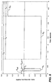
- Figure 8 shows data for a control solution, plasma, a blood sample with 48% hematocrit, and a blood sample is 77% hematocrit.
- a potential of 20 mV was applied for the first 1 second and current values at 0.2 to 0.5 seconds were summed.
- the summed current values were sufficient to distinguish between a control solution (that was substantially devoid of interferents) and blood samples.
- the method disclosed herein includes the step of calculating a first reference value that is representative of the redox concentration in the sample and a second reference value that is representative of the rate of reaction of the sample with the reagent.
- the first reference value is an interferent oxidation current and the second reference value is a reaction completion percentage.
- blood usually contains various endogenous redox species or "interferents” such as ascorbic acid and uric acid, as well as exogenously derived interferents such as gentisic acid (gentisic acid is a metabolite of aspirin).
- endogenous interferents are chemical species that can be easily oxidized at an electrode and are usually present in blood within a physiological range for healthy individuals.
- Exogenously derived interferents are also a chemical species that can be easily oxidized at an electrode, but are not usually present in blood unless they are inputted into the body via consumption, injection, absorption, and the like.
- Control solution can be formulated to be either essentially free of antioxidants or to have a relatively high interferent concentration compared to the interferent concentration in a blood sample.
- the magnitude of the first current transient should be smaller for control solution than for a blood sample as shown in Figure 9 .
- the magnitude of the first current transient should be larger for control solution than for a blood sample (data not shown).
- An interferent index can be calculated based on the current values within first current transient.
- the interferent index can include a summation of current values at two points in time during the first current transient. In one example, the current values at 0.3 and 0.35 seconds can be used.
- E 1 ' When a small potential E 1 ' is applied for the entire period between when fill is detected and E 2 , the interferent index is preferably obtained by summing two values over a longer period, for example 0.2 seconds to 0.5 seconds.
- the interferent index will be proportional to the interferent concentration and should not substantially depend on the glucose concentration. Therefore, in theory, the test meter should be able to distinguish whether the sample is blood or control solution based on the interferent index.
- using only the interferent index did not always sufficiently discriminate between blood and control solution.
- blood typically has a much higher interferent concentration
- an additional factor is implemented to enable the test meter to sufficiently discriminate between blood and control solution.
- the additional factor used for helping discriminate between blood and control solution can be a residual reaction index which is a function of the percent of remaining substrate which would have reacted if given enough time.
- the residual reaction index relates to the reaction rate in that a high reaction rate can cause the substrate to be depleted by the reaction.
- the residual reaction index will also depend on the initial magnitude of the substrate concentration.
- Reagent layer 72 can include glucose dehydrogenase (GDH) based on the PQQ co-factor and ferricyanide.
- GDH glucose dehydrogenase
- ox glucose oxidized by GDH (ox) and in the process converts GDH (ox) to GDH (red) , as shown in Eq.3.
- GDH (ox) refers to the oxidized state of GDH
- GDH (red) refers to the reduced state of GDH.
- GDH (red) is regenerated back to its active oxidized state by ferricyanide (i.e. oxidized mediator or Fe(CN) 6 3- ) as shown in Eq. 4.
- ferricyanide i.e. oxidized mediator or Fe(CN) 6 3-
- ferrocyanide i.e. reduced mediator or Fe(CN) 6 4-
- the rate of glucose consumption based on Eq.'s 3 and 4 is faster for control solution than blood.
- control solution is less viscous than blood causing the reaction rate of Eq. 3 and 4 to be faster for control solution.
- the reaction rate is faster for control solution because a portion of the glucose present in the blood sample must diffuse out of the red blood cells to participate in Eq. 3. This extra step of glucose diffusion out of the red blood cells slows down the reaction rate to some measurable degree.
- Figure 9 shows that the reaction rate for blood is slower than for control solution as evidenced by the fact that the general absolute slope value (e.g., between 1.2 and 4 seconds) for the second current transient is less for the blood sample. Because of the faster reaction rates in control solution compared to blood, the residual reaction index for control solution will generally be lower than for blood.
- the residual reaction index is a number which is related to the percent of glucose which has not been consumed. A relatively low residual reaction index will indicate that the reactions of Eq.'s 3 and 4 are close to completion. In contrast, a relatively high residual reaction index will indicate that the reaction is not close to completion.
- the residual reaction index can be an absolute ratio of a current value of third current transient divided by a current value of the second current transient, as shown in Eq. 5. abs i 4.15 i 3.8
- the current value at 3.8 seconds for the second current transient is used.
- the time of 3.8 seconds was chosen empirically, however, one skilled in the art will appreciate that other current values can be used.
- a current value towards the end of the second current transient can be chosen.
- reduced mediator is oxidized at second electrode 164.
- the current values measured during second current transient time interval T 2 were ascribed to ferrocyanide generated by reagent layer 72 at first electrode 166 which then diffused to second electrode 164 and became oxidized. It is assumed that reagent layer 72 remains close to first electrode 166 after it dissolves in blood causing most of the ferrocyanide generated by reagent layer 72 to also be close to first electrode 166. A portion of this generated ferrocyanide can diffuse to second electrode 164.
- the current value at 4.15 seconds was used.
- Other current values from the third current transient can be chosen, however current value towards the beginning of the third current transient are preferred.
- reduced mediator is oxidized at first electrode 166.
- the current values measured during second current transient time interval T 2 were ascribed to ferrocyanide generated by reagent layer 72 at first electrode 166. Therefore, the current values for the third current transient will be larger than the second current transient because most of the ferrocyanide will be close to first electrode 166 because first electrode 166 was coated with reagent layer 72.
- third current transient will also be larger than second current transient because it occurs later in the glucose test allowing for more ferrocyanide to be generated.
- the absolute ratio as shown in Eq. 5 will be larger if the glucose reaction is still far from completion at the time of the measurement.
- This chart shows that the residual reaction index is relatively high when the % of substrate consumed is low and that the residual reaction index is relatively low when the % of substrate consumed is high for a given sample type/hematocrit value.
- the % of substrate consumed is derived from a ratio C o YSI , where C o is the substrate concentration at the electrode surface and YSI is the substrate concentration using a standard reference technique.
- C o i ss L 2 FAD
- L the distance between first electrode 166 and second electrode 164
- F Faraday's constant
- A the area of first electrode 166
- D the diffusion coefficient
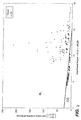
- Figure 11 is a chart showing a relationship between an interferent index and a residual reaction index for a plurality of blood samples and control solution samples.
- the interferent index is i (0.3) + i (0.35) and the residual reaction index is abs i 4.15 i 3.8 .
- a discrimination line was derived to allow the test meter to determine whether the sample was control solution or blood. For all of the control solution samples tested, the interferent index was plotted versus the residual reaction index. Next, a line was calculated using linear regression for control solution samples. After calculating an equation for the line, the perpendicular bias between each data point and the line was calculated. The perpendicular bias represents the shortest distance between the data point and the line as opposed to a vertical bias which is commonly calculated. A standard deviation was determined for all of the perpendicular biases (SD perp ). Lastly, the line is shifted 3* SD perp units towards the data points for the blood group. The reason for this approach is that the data for the control solution group show very little scatter and therefore the "99% confidence limit" of the control solution group is well-defined.
- the information obtained from this statistical analysis of the residual reaction index and the interferent index can be used by the test meter to distinguish control solutions from blood samples.
- the test meter can calculate the interferent index and residual reaction index and use these values in association with the derived discrimination line (or an equation representing the discrimination line) to distinguish control solutions from blood samples.
- control fluid Preparation of control fluid is disclosed below.
- the prepared control fluid was used in the experiments which produced the data illustrated in Figures 7 and 11 .
- First citraconic buffer pH 6.5 ⁇ 0.1 was prepared by dissolving required quantities of citraconic acid and dipotassium citraconate in deionized water. Next, Methyl Paraben was added and the solution was stirred until the preservative was fully dissolved. Subsequently Dextran T-500, Germal II, Pluronic 25R2 and 1-[(6- methoxy-4-sulfo-m-tolyl)azo]-2-naphthol-6-sulfonic acid disodium salt were added sequentially, following complete dissolution of the previously added chemical. At this point, the pH of the control fluid was verified, followed by addition of the requisite quantity of glucose to obtain a low, normal or high glucose level of control fluid.
- control fluid was left at room temperature overnight.
- glucose concentration was verified using a Model 2700 Select Biochemistry Analyzer manufactured by Yellow Springs Instrument Co., Inc.
- the dye used in this control solution has a blue color which reduces the possibility of a user confusing control solution with blood, which is normally red.
Landscapes
- Chemical & Material Sciences (AREA)
- Health & Medical Sciences (AREA)
- Life Sciences & Earth Sciences (AREA)
- Organic Chemistry (AREA)
- Wood Science & Technology (AREA)
- Proteomics, Peptides & Aminoacids (AREA)
- Zoology (AREA)
- Engineering & Computer Science (AREA)
- Immunology (AREA)
- Biochemistry (AREA)
- Molecular Biology (AREA)
- Physics & Mathematics (AREA)
- General Health & Medical Sciences (AREA)
- Analytical Chemistry (AREA)
- Hematology (AREA)
- General Engineering & Computer Science (AREA)
- Bioinformatics & Cheminformatics (AREA)
- Biophysics (AREA)
- Biotechnology (AREA)
- Genetics & Genomics (AREA)
- Microbiology (AREA)
- Chemical Kinetics & Catalysis (AREA)
- Electrochemistry (AREA)
- General Physics & Mathematics (AREA)
- Pathology (AREA)
- Emergency Medicine (AREA)
- Investigating Or Analysing Biological Materials (AREA)
Claims (16)
- Procédé visant à établir une distinction entre un échantillon de sang et un échantillon de solution témoin, le procédé comprenant les étapes consistant à :(a) introduire un échantillon dans une cellule électrochimique, la cellule électrochimique comprenant :(i) deux électrodes dans une relation espacée ; et(ii) un réactif ;(b) appliquer un premier potentiel d'essai (E1), ayant une première polarité, entre les électrodes, et mesurer un premier transitoire de courant (ia(t)) ;(c) appliquer un deuxième potentiel d'essai (E2), ayant la première polarité, entre les électrodes, et mesurer un deuxième transitoire de courant (ib(t)) ;(d) appliquer un troisième potentiel d'essai (E3), ayant une deuxième polarité opposée à la première polarité, entre les électrodes, et mesurer un troisième transitoire de courant (ic(t)) ;(e) calculer, sur la base du premier transitoire de courant, une première valeur de référence liée à la quantité d'espèces redox dans l'échantillon ;(f) calculer, sur la base des deuxième et troisième transitoires de courant, une deuxième valeur de référence liée à la cinétique réactionnelle ; et(g) déterminer, sur la base des première et deuxième valeurs de référence, si l'échantillon est une solution témoin ou un échantillon de sang.
- Procédé de la revendication 1, dans lequel la première valeur de référence est proportionnelle à une concentration d'un interférent dans l'échantillon.
- Procédé de la revendication 2, dans lequel la première valeur de référence est un indice d'interférent calculé sur la base d'au moins une valeur de courant issue du premier transitoire.
- Procédé de la revendication 1, dans lequel la deuxième valeur de référence est une fonction d'un pourcentage d'achèvement d'une réaction chimique.
- Procédé de la revendication 4, dans lequel la deuxième valeur de référence est un indice de réaction résiduelle calculé sur la base d'au moins une valeur de courant issue du deuxième transitoire de courant et d'au moins une valeur de courant issue du troisième transitoire de courant.
- Procédé de la revendication 5, dans lequel l'indice de réaction résiduelle est calculé sur la base d'un rapport entre une deuxième valeur de courant et une troisième valeur de courant.
- Procédé de la revendication 1, comprenant en outre l'étape consistant à mesurer une concentration d'un analyte.
- Procédé de la revendication 7, dans lequel si l'échantillon se révèle être une solution témoin, la concentration d'analyte associée à l'échantillon témoin est signalée.
- Procédé de la revendication 1, dans lequel l'étape (g) comprend en outre l'utilisation d'une classification statistique pour déterminer si l'échantillon est une solution témoin ou un échantillon de sang.
- Procédé de la revendication 1, dans lequel une équation représentant une ligne de discrimination est utilisée à l'étape (g) pour évaluer les première et deuxième valeurs de référence.
- Procédé de la revendication 1, comprenant en outre l'étape consistant à appliquer un premier potentiel en circuit ouvert à la cellule électrochimique avant l'étape d'application du premier potentiel d'essai.
- Procédé de la revendication 11, comprenant en outre l'étape consistant à appliquer un deuxième potentiel en circuit ouvert à la cellule électrochimique après l'étape d'application du premier potentiel d'essai.
- Système servant à établir une distinction entre un échantillon de sang et un échantillon de solution témoin, le système comprenant :A. une bandelette réactive comportant des contacts électriques destinés à s'accoupler à un contrôleur et une cellule électrochimique comprenant :(i) une première électrode et une deuxième électrode dans une relation espacée ; et(ii) un réactif ; etB. un contrôleur comportant un processeur adapté pour recevoir des données de courant issues de la bandelette réactive, et un stockage de données contenant des critères de distinction pour distinguer un échantillon de sang d'un échantillon témoin sur la base d'une concentration d'antioxydant et d'une cinétique réactionnelle, le contrôleur étant en outre adapté pour :(a) appliquer un premier potentiel, ayant une première polarité, entre les électrodes, et mesurer un premier transitoire de courant ;(b) appliquer un deuxième potentiel, ayant la première polarité, entre les électrodes, et mesurer un deuxième transitoire de courant ;(c) appliquer un troisième potentiel, ayant une deuxième polarité opposée à la première polarité, entre les électrodes, et mesurer le troisième transitoire de courant ;(d) calculer, sur la base du premier transitoire de courant, une première valeur de référence liée à la quantité d'espèces redox dans l'échantillon ;(e) calculer, sur la base des deuxième et troisième transitoires de courant, une deuxième valeur de référence liée à la cinétique réactionnelle ; et(f) déterminer, sur la base des première et deuxième valeurs de référence, si l'échantillon est une solution témoin ou un échantillon de sang.
- Système de la revendication 13, dans lequel le critère de distinction est dérivé d'un indice d'interférent qui est représentatif d'une concentration d'antioxydant et d'un indice de réaction résiduelle qui est représentatif d'une cinétique réactionnelle.
- Système de la revendication 14, dans lequel le critère de distinction comporte une ligne de discrimination dérivée empiriquement.
- Système de la revendication 13, comprenant en outre une solution témoin qui est sensiblement dépourvue d'espèces redox.
Priority Applications (2)
| Application Number | Priority Date | Filing Date | Title |
|---|---|---|---|
| EP10178982.4A EP2284533B1 (fr) | 2006-03-31 | 2007-03-30 | Un procédé de solution de contrôle contre la discrimination d'un échantillon physiologique |
| EP10178905.5A EP2267149B1 (fr) | 2006-03-31 | 2007-03-30 | Procédé de discrimination entre une solution de contrôle et un échantillon physiologique |
Applications Claiming Priority (1)
| Application Number | Priority Date | Filing Date | Title |
|---|---|---|---|
| US11/278,333 US8529751B2 (en) | 2006-03-31 | 2006-03-31 | Systems and methods for discriminating control solution from a physiological sample |
Related Child Applications (4)
| Application Number | Title | Priority Date | Filing Date |
|---|---|---|---|
| EP10178905.5A Division EP2267149B1 (fr) | 2006-03-31 | 2007-03-30 | Procédé de discrimination entre une solution de contrôle et un échantillon physiologique |
| EP10178905.5A Division-Into EP2267149B1 (fr) | 2006-03-31 | 2007-03-30 | Procédé de discrimination entre une solution de contrôle et un échantillon physiologique |
| EP10178982.4A Division EP2284533B1 (fr) | 2006-03-31 | 2007-03-30 | Un procédé de solution de contrôle contre la discrimination d'un échantillon physiologique |
| EP10178982.4A Division-Into EP2284533B1 (fr) | 2006-03-31 | 2007-03-30 | Un procédé de solution de contrôle contre la discrimination d'un échantillon physiologique |
Publications (2)
| Publication Number | Publication Date |
|---|---|
| EP1840219A1 EP1840219A1 (fr) | 2007-10-03 |
| EP1840219B1 true EP1840219B1 (fr) | 2016-05-18 |
Family
ID=38180140
Family Applications (3)
| Application Number | Title | Priority Date | Filing Date |
|---|---|---|---|
| EP10178905.5A Not-in-force EP2267149B1 (fr) | 2006-03-31 | 2007-03-30 | Procédé de discrimination entre une solution de contrôle et un échantillon physiologique |
| EP07251388.0A Not-in-force EP1840219B1 (fr) | 2006-03-31 | 2007-03-30 | Système et procédé de distinguer une solution de contrôle d'un échantillon physiologique de sang |
| EP10178982.4A Not-in-force EP2284533B1 (fr) | 2006-03-31 | 2007-03-30 | Un procédé de solution de contrôle contre la discrimination d'un échantillon physiologique |
Family Applications Before (1)
| Application Number | Title | Priority Date | Filing Date |
|---|---|---|---|
| EP10178905.5A Not-in-force EP2267149B1 (fr) | 2006-03-31 | 2007-03-30 | Procédé de discrimination entre une solution de contrôle et un échantillon physiologique |
Family Applications After (1)
| Application Number | Title | Priority Date | Filing Date |
|---|---|---|---|
| EP10178982.4A Not-in-force EP2284533B1 (fr) | 2006-03-31 | 2007-03-30 | Un procédé de solution de contrôle contre la discrimination d'un échantillon physiologique |
Country Status (6)
| Country | Link |
|---|---|
| US (3) | US8529751B2 (fr) |
| EP (3) | EP2267149B1 (fr) |
| JP (1) | JP4891821B2 (fr) |
| AU (2) | AU2007201377B2 (fr) |
| CA (2) | CA2582643C (fr) |
| ES (3) | ES2663070T3 (fr) |
Families Citing this family (98)
| Publication number | Priority date | Publication date | Assignee | Title |
|---|---|---|---|---|
| US7494816B2 (en) * | 1997-12-22 | 2009-02-24 | Roche Diagnostic Operations, Inc. | System and method for determining a temperature during analyte measurement |
| US8071384B2 (en) * | 1997-12-22 | 2011-12-06 | Roche Diagnostics Operations, Inc. | Control and calibration solutions and methods for their use |
| US6391005B1 (en) | 1998-03-30 | 2002-05-21 | Agilent Technologies, Inc. | Apparatus and method for penetration with shaft having a sensor for sensing penetration depth |
| US8641644B2 (en) | 2000-11-21 | 2014-02-04 | Sanofi-Aventis Deutschland Gmbh | Blood testing apparatus having a rotatable cartridge with multiple lancing elements and testing means |
| US7041068B2 (en) | 2001-06-12 | 2006-05-09 | Pelikan Technologies, Inc. | Sampling module device and method |
| US9226699B2 (en) | 2002-04-19 | 2016-01-05 | Sanofi-Aventis Deutschland Gmbh | Body fluid sampling module with a continuous compression tissue interface surface |
| CA2448902C (fr) | 2001-06-12 | 2010-09-07 | Pelikan Technologies, Inc. | Autopiqueur a optimisation automatique presentant des moyens d'adaptation aux variations temporelles des proprietes cutanees |
| AU2002348683A1 (en) | 2001-06-12 | 2002-12-23 | Pelikan Technologies, Inc. | Method and apparatus for lancet launching device integrated onto a blood-sampling cartridge |
| US7344507B2 (en) | 2002-04-19 | 2008-03-18 | Pelikan Technologies, Inc. | Method and apparatus for lancet actuation |
| WO2002100460A2 (fr) | 2001-06-12 | 2002-12-19 | Pelikan Technologies, Inc. | Actionneur electrique de lancette |
| US9795747B2 (en) | 2010-06-02 | 2017-10-24 | Sanofi-Aventis Deutschland Gmbh | Methods and apparatus for lancet actuation |
| US9427532B2 (en) | 2001-06-12 | 2016-08-30 | Sanofi-Aventis Deutschland Gmbh | Tissue penetration device |
| US7981056B2 (en) | 2002-04-19 | 2011-07-19 | Pelikan Technologies, Inc. | Methods and apparatus for lancet actuation |
| US8337419B2 (en) | 2002-04-19 | 2012-12-25 | Sanofi-Aventis Deutschland Gmbh | Tissue penetration device |
| US7901362B2 (en) | 2002-04-19 | 2011-03-08 | Pelikan Technologies, Inc. | Method and apparatus for penetrating tissue |
| US7226461B2 (en) | 2002-04-19 | 2007-06-05 | Pelikan Technologies, Inc. | Method and apparatus for a multi-use body fluid sampling device with sterility barrier release |
| US8267870B2 (en) | 2002-04-19 | 2012-09-18 | Sanofi-Aventis Deutschland Gmbh | Method and apparatus for body fluid sampling with hybrid actuation |
| US7674232B2 (en) | 2002-04-19 | 2010-03-09 | Pelikan Technologies, Inc. | Method and apparatus for penetrating tissue |
| US7892185B2 (en) | 2002-04-19 | 2011-02-22 | Pelikan Technologies, Inc. | Method and apparatus for body fluid sampling and analyte sensing |
| US9314194B2 (en) | 2002-04-19 | 2016-04-19 | Sanofi-Aventis Deutschland Gmbh | Tissue penetration device |
| US7909778B2 (en) | 2002-04-19 | 2011-03-22 | Pelikan Technologies, Inc. | Method and apparatus for penetrating tissue |
| US7976476B2 (en) | 2002-04-19 | 2011-07-12 | Pelikan Technologies, Inc. | Device and method for variable speed lancet |
| US8221334B2 (en) | 2002-04-19 | 2012-07-17 | Sanofi-Aventis Deutschland Gmbh | Method and apparatus for penetrating tissue |
| US8360992B2 (en) | 2002-04-19 | 2013-01-29 | Sanofi-Aventis Deutschland Gmbh | Method and apparatus for penetrating tissue |
| US7331931B2 (en) | 2002-04-19 | 2008-02-19 | Pelikan Technologies, Inc. | Method and apparatus for penetrating tissue |
| US8784335B2 (en) | 2002-04-19 | 2014-07-22 | Sanofi-Aventis Deutschland Gmbh | Body fluid sampling device with a capacitive sensor |
| US7232451B2 (en) | 2002-04-19 | 2007-06-19 | Pelikan Technologies, Inc. | Method and apparatus for penetrating tissue |
| US7491178B2 (en) | 2002-04-19 | 2009-02-17 | Pelikan Technologies, Inc. | Method and apparatus for penetrating tissue |
| US7892183B2 (en) | 2002-04-19 | 2011-02-22 | Pelikan Technologies, Inc. | Method and apparatus for body fluid sampling and analyte sensing |
| US7297122B2 (en) | 2002-04-19 | 2007-11-20 | Pelikan Technologies, Inc. | Method and apparatus for penetrating tissue |
| US8579831B2 (en) | 2002-04-19 | 2013-11-12 | Sanofi-Aventis Deutschland Gmbh | Method and apparatus for penetrating tissue |
| US9795334B2 (en) | 2002-04-19 | 2017-10-24 | Sanofi-Aventis Deutschland Gmbh | Method and apparatus for penetrating tissue |
| US7547287B2 (en) | 2002-04-19 | 2009-06-16 | Pelikan Technologies, Inc. | Method and apparatus for penetrating tissue |
| US8702624B2 (en) | 2006-09-29 | 2014-04-22 | Sanofi-Aventis Deutschland Gmbh | Analyte measurement device with a single shot actuator |
| US9248267B2 (en) | 2002-04-19 | 2016-02-02 | Sanofi-Aventis Deustchland Gmbh | Tissue penetration device |
| US7229458B2 (en) | 2002-04-19 | 2007-06-12 | Pelikan Technologies, Inc. | Method and apparatus for penetrating tissue |
| US8574895B2 (en) | 2002-12-30 | 2013-11-05 | Sanofi-Aventis Deutschland Gmbh | Method and apparatus using optical techniques to measure analyte levels |
| EP2238892A3 (fr) | 2003-05-30 | 2011-02-09 | Pelikan Technologies Inc. | Appareil pour prendre de fluide du corps |
| ES2490740T3 (es) | 2003-06-06 | 2014-09-04 | Sanofi-Aventis Deutschland Gmbh | Aparato para toma de muestras de fluido sanguíneo y detección de analitos |
| WO2006001797A1 (fr) | 2004-06-14 | 2006-01-05 | Pelikan Technologies, Inc. | Element penetrant peu douloureux |
| EP1671096A4 (fr) | 2003-09-29 | 2009-09-16 | Pelikan Technologies Inc | Procede et appareil permettant d'obtenir un dispositif de capture d'echantillons ameliore |
| EP1680014A4 (fr) | 2003-10-14 | 2009-01-21 | Pelikan Technologies Inc | Procede et appareil fournissant une interface-utilisateur variable |
| WO2005065414A2 (fr) | 2003-12-31 | 2005-07-21 | Pelikan Technologies, Inc. | Procede et appareil permettant d'ameliorer le flux fluidique et le prelevement d'echantillons |
| US7822454B1 (en) | 2005-01-03 | 2010-10-26 | Pelikan Technologies, Inc. | Fluid sampling device with improved analyte detecting member configuration |
| US8828203B2 (en) | 2004-05-20 | 2014-09-09 | Sanofi-Aventis Deutschland Gmbh | Printable hydrogels for biosensors |
| US9775553B2 (en) | 2004-06-03 | 2017-10-03 | Sanofi-Aventis Deutschland Gmbh | Method and apparatus for a fluid sampling device |
| EP1765194A4 (fr) | 2004-06-03 | 2010-09-29 | Pelikan Technologies Inc | Procede et appareil pour la fabrication d'un dispositif d'echantillonnage de liquides |
| US8652831B2 (en) | 2004-12-30 | 2014-02-18 | Sanofi-Aventis Deutschland Gmbh | Method and apparatus for analyte measurement test time |
| US8529751B2 (en) | 2006-03-31 | 2013-09-10 | Lifescan, Inc. | Systems and methods for discriminating control solution from a physiological sample |
| EP2017608A4 (fr) * | 2006-04-19 | 2012-12-12 | Panasonic Corp | Biocapteur |
| US9046480B2 (en) | 2006-10-05 | 2015-06-02 | Lifescan Scotland Limited | Method for determining hematocrit corrected analyte concentrations |
| ES2375288T3 (es) | 2006-10-05 | 2012-02-28 | Lifescan Scotland Limited | Procedimiento para determinar concentraciones de analito corregidas con hematocrito. |
| EP2080022B1 (fr) | 2006-10-05 | 2015-05-13 | Lifescan Scotland Ltd | Procedes de determination d'une concentration d'analyte par des algorithmes de traitement de signaux |
| ES2397663T3 (es) | 2006-10-05 | 2013-03-08 | Lifescan Scotland Limited | Sistemas y procedimientos para determinar una concentración de un analito sustancialmente independiente del hematocrito |
| US20090026094A1 (en) * | 2007-05-11 | 2009-01-29 | Home Diagnostics, Inc. | Two-pulse systems and methods for determining analyte concentration |
| US8080153B2 (en) * | 2007-05-31 | 2011-12-20 | Abbott Diabetes Care Inc. | Analyte determination methods and devices |
| AU2011224097B2 (en) * | 2007-09-28 | 2012-09-20 | Lifescan, Inc. | Systems and methods for discriminating control solution from a physiological sample |
| US8778168B2 (en) * | 2007-09-28 | 2014-07-15 | Lifescan, Inc. | Systems and methods of discriminating control solution from a physiological sample |
| EP2211169A1 (fr) * | 2007-10-31 | 2010-07-28 | ARKRAY, Inc. | Procede d'identification de liquide de controle et dispositif d'analyse |
| WO2009076302A1 (fr) | 2007-12-10 | 2009-06-18 | Bayer Healthcare Llc | Marqueurs de contrôle pour la détection automatique d'une solution de contrôle et procédés d'utilisation |
| US8603768B2 (en) * | 2008-01-17 | 2013-12-10 | Lifescan, Inc. | System and method for measuring an analyte in a sample |
| AU2015203087B2 (en) * | 2008-01-17 | 2017-03-16 | Lifescan, Inc. | System and method for measuring an analyte in a sample |
| US8431011B2 (en) | 2008-01-31 | 2013-04-30 | Abbott Diabetes Care Inc. | Method for automatically and rapidly distinguishing between control and sample solutions in a biosensor strip |
| EP2265324B1 (fr) | 2008-04-11 | 2015-01-28 | Sanofi-Aventis Deutschland GmbH | Système intégré de mesure d'analytes |
| US20090305317A1 (en) * | 2008-06-05 | 2009-12-10 | Brauer Jacob S | User interface for testing device |
| US8551320B2 (en) * | 2008-06-09 | 2013-10-08 | Lifescan, Inc. | System and method for measuring an analyte in a sample |
| AU2012201912B2 (en) * | 2008-06-09 | 2013-06-20 | Lifescan, Inc. | System and method for measuring an analyte in a sample |
| US8178313B2 (en) * | 2008-06-24 | 2012-05-15 | Lifescan, Inc. | Method for determining an analyte in a bodily fluid |
| TWI495874B (zh) * | 2008-10-17 | 2015-08-11 | Apex Biotechnology Corp | 非酵素型電化學檢測系統之品管控制液及其使用方法 |
| US9375169B2 (en) | 2009-01-30 | 2016-06-28 | Sanofi-Aventis Deutschland Gmbh | Cam drive for managing disposable penetrating member actions with a single motor and motor and control system |
| US20100326824A1 (en) * | 2009-06-24 | 2010-12-30 | Lifescan, Inc. | Analyte test strip with combination electrode contact and meter identification feature |
| CA2957078C (fr) | 2009-06-30 | 2019-04-30 | Lifescan, Inc | Procedes et dispositif de test d'analyte pour calculer une therapie par insuline basale |
| BR112012004976A2 (pt) * | 2009-09-04 | 2021-09-21 | Lifescan Scotland Limited | Método e sistema para medição de glicose |
| US8545693B2 (en) | 2009-09-29 | 2013-10-01 | Lifescan Scotland Limited | Analyte measurment method and system |
| IN2012DN02710A (fr) | 2009-09-29 | 2015-09-11 | Lifescan Scotland Ltd | |
| EP2590098B1 (fr) | 2010-02-25 | 2014-11-05 | Lifescan Scotland Limited | Système et procédé de test d'analyte avec notification de tendances de glycémie élevée et faible |
| US8965476B2 (en) | 2010-04-16 | 2015-02-24 | Sanofi-Aventis Deutschland Gmbh | Tissue penetration device |
| RU2596501C2 (ru) * | 2010-07-19 | 2016-09-10 | Цилаг Гмбх Интернэшнл | Система и способ измерения аналита в образце |
| US20120048746A1 (en) * | 2010-08-30 | 2012-03-01 | Cilag Gmbh International | Analyte test strip with electrically distinguishable divided electrode |
| US8932445B2 (en) | 2010-09-30 | 2015-01-13 | Cilag Gmbh International | Systems and methods for improved stability of electrochemical sensors |
| US9028661B2 (en) * | 2011-01-05 | 2015-05-12 | Microchip Technology Incorporated | Glucose measurement using a current source |
| US8956518B2 (en) | 2011-04-20 | 2015-02-17 | Lifescan, Inc. | Electrochemical sensors with carrier field |
| US10888947B2 (en) | 2011-06-27 | 2021-01-12 | Illinois Tool Works Inc. | Workpiece-based setting of weld parameters |
| US9523653B2 (en) | 2013-05-09 | 2016-12-20 | Changsha Sinocare Inc. | Disposable test sensor with improved sampling entrance |
| GB2515299B (en) * | 2013-06-18 | 2015-12-30 | Suresensors Ltd | Methods and apparatus for determining analyte in a sample |
| US10083627B2 (en) | 2013-11-05 | 2018-09-25 | Lincoln Global, Inc. | Virtual reality and real welding training system and method |
| US9518951B2 (en) | 2013-12-06 | 2016-12-13 | Changsha Sinocare Inc. | Disposable test sensor with improved sampling entrance |
| US9897566B2 (en) | 2014-01-13 | 2018-02-20 | Changsha Sinocare Inc. | Disposable test sensor |
| US9939401B2 (en) | 2014-02-20 | 2018-04-10 | Changsha Sinocare Inc. | Test sensor with multiple sampling routes |
| JP6569415B2 (ja) * | 2015-09-15 | 2019-09-04 | 株式会社リコー | 表示入力装置、画像形成装置及び電子機器と表示制御方法並びにプログラム |
| KR102540664B1 (ko) * | 2015-11-03 | 2023-06-08 | 삼성전자주식회사 | 바이오 센서 및 그의 센싱 방법 |
| SI3220137T1 (sl) * | 2016-03-14 | 2019-05-31 | F. Hoffmann-La Roche Ag | Postopek za odkrivanje doprinosa interferenta v biosenzorju |
| CN113702267B (zh) * | 2020-05-22 | 2025-08-12 | 深圳迈瑞动物医疗科技股份有限公司 | 血红蛋白浓度的检测方法及血液细胞分析仪 |
| US20240035065A1 (en) * | 2020-12-07 | 2024-02-01 | The University Of North Carolina At Chapel Hill | Method for measurement in biosensors |
| CN120102663A (zh) * | 2022-05-09 | 2025-06-06 | 深圳市理邦精密仪器股份有限公司 | 血样分析模组 |
| US20230375495A1 (en) | 2022-05-20 | 2023-11-23 | Lifescan Ip Holdings, Llc | Biosensor and related method of manufacture |
| CN120232969A (zh) * | 2023-12-28 | 2025-07-01 | 江苏鱼跃凯立特生物科技有限公司 | 一种区分质控液与生物样品的方法 |
| WO2026041553A1 (fr) * | 2024-08-23 | 2026-02-26 | Roche Diabetes Care Gmbh | Procédé de détermination d'un état d'une électrode d'un capteur d'analyte électrochimique |
Family Cites Families (211)
| Publication number | Priority date | Publication date | Assignee | Title |
|---|---|---|---|---|
| US1030185A (en) | 1911-12-04 | 1912-06-18 | Abram Jacobson | Electric switch. |
| BE758318A (fr) * | 1969-12-01 | 1971-04-30 | Technicon Instr | Procede et appareil pour la determination automatique de haute precision de l'hematocrite d'echantillons de sang total |
| SE399768B (sv) * | 1975-09-29 | 1978-02-27 | Lilja Jan E | Kyvett for provtagning, blandning av, provet med ett reagensmedel och direkt utforande av, serskilt optisk, analys av det med reagensmedlet blandade provet |
| JPS5912135B2 (ja) * | 1977-09-28 | 1984-03-21 | 松下電器産業株式会社 | 酵素電極 |
| NL7903113A (nl) | 1978-05-05 | 1979-11-07 | Baker Chem Co J T | Kinetische meting van glucoseconcentraties in lichaamsvloeistoffen en daartoe te gebruiken preparaten. |
| US4250257A (en) | 1978-08-24 | 1981-02-10 | Technicon Instruments Corporation | Whole blood analyses in porous media |
| US4254083A (en) * | 1979-07-23 | 1981-03-03 | Eastman Kodak Company | Structural configuration for transport of a liquid drop through an ingress aperture |
| US4233029A (en) | 1978-10-25 | 1980-11-11 | Eastman Kodak Company | Liquid transport device and method |
| JPS5594560U (fr) * | 1978-12-20 | 1980-06-30 | ||
| DE2913553C2 (de) * | 1979-04-04 | 1981-09-17 | Boehringer Mannheim Gmbh, 6800 Mannheim | Verfahren und Reagenz zur enzymatischen Bestimmung von Enzymsubstraten |
| US4307188A (en) | 1979-09-06 | 1981-12-22 | Miles Laboratories, Inc. | Precursor indicator compositions |
| US4301412A (en) | 1979-10-29 | 1981-11-17 | United States Surgical Corporation | Liquid conductivity measuring system and sample cards therefor |
| US4303887A (en) | 1979-10-29 | 1981-12-01 | United States Surgical Corporation | Electrical liquid conductivity measuring system |
| US4301414A (en) | 1979-10-29 | 1981-11-17 | United States Surgical Corporation | Disposable sample card and method of making same |
| SE419903B (sv) * | 1980-03-05 | 1981-08-31 | Enfors Sven Olof | Enzymelektrod |
| US4774039A (en) * | 1980-03-14 | 1988-09-27 | Brunswick Corporation | Dispersing casting of integral skinned highly asymmetric polymer membranes |
| US4629563B1 (en) | 1980-03-14 | 1997-06-03 | Memtec North America | Asymmetric membranes |
| US4404066A (en) * | 1980-08-25 | 1983-09-13 | The Yellow Springs Instrument Company | Method for quantitatively determining a particular substrate catalyzed by a multisubstrate enzyme |
| US4436812A (en) | 1980-10-29 | 1984-03-13 | Fuji Electric Co., Ltd. | Process of calibrating a blood sugar analyzing apparatus |
| DE3103464C2 (de) | 1981-02-02 | 1984-10-11 | Gkss - Forschungszentrum Geesthacht Gmbh, 2054 Geesthacht | Dichtungsrahmen für Elektrodialyse-Membranstapel |
| DE3278334D1 (en) * | 1981-10-23 | 1988-05-19 | Genetics Int Inc | Sensor for components of a liquid mixture |
| US4431004A (en) * | 1981-10-27 | 1984-02-14 | Bessman Samuel P | Implantable glucose sensor |
| DE3202067C2 (de) * | 1982-01-23 | 1984-06-20 | Holger Dr. 5100 Aachen Kiesewetter | Vorrichtung zur Bestimmung des Hämatokritwertes |
| DE3228542A1 (de) * | 1982-07-30 | 1984-02-02 | Siemens AG, 1000 Berlin und 8000 München | Verfahren zur bestimmung der konzentration elektrochemisch umsetzbarer stoffe |
| US4552840A (en) | 1982-12-02 | 1985-11-12 | California And Hawaiian Sugar Company | Enzyme electrode and method for dextran analysis |
| CA1226036A (fr) | 1983-05-05 | 1987-08-25 | Irving J. Higgins | Materiel d'analyse et ses electrodes-sondes |
| US5509410A (en) * | 1983-06-06 | 1996-04-23 | Medisense, Inc. | Strip electrode including screen printing of a single layer |
| CA1219040A (fr) | 1983-05-05 | 1987-03-10 | Elliot V. Plotkin | Mesure de reactions catalysees par des enzymes |
| US4533440A (en) * | 1983-08-04 | 1985-08-06 | General Electric Company | Method for continuous measurement of the sulfite/sulfate ratio |
| US4517291A (en) * | 1983-08-15 | 1985-05-14 | E. I. Du Pont De Nemours And Company | Biological detection process using polymer-coated electrodes |
| SE8305704D0 (sv) * | 1983-10-18 | 1983-10-18 | Leo Ab | Cuvette |
| GB8330268D0 (en) | 1983-11-12 | 1983-12-21 | Lion Lab Ltd | Discriminant analysis of gas constituents |
| US4508613A (en) * | 1983-12-19 | 1985-04-02 | Gould Inc. | Miniaturized potassium ion sensor |
| GB2154735B (en) | 1984-01-27 | 1987-07-15 | Menarini Sas | Reagent for determining blood glucose content |
| US5141868A (en) * | 1984-06-13 | 1992-08-25 | Internationale Octrooi Maatschappij "Octropa" Bv | Device for use in chemical test procedures |
| SE8403628D0 (sv) | 1984-07-09 | 1984-07-09 | Cerac Inst Sa | Vetskefordelningsanordning vid forskremningsmaskiner |
| US5171689A (en) | 1984-11-08 | 1992-12-15 | Matsushita Electric Industrial Co., Ltd. | Solid state bio-sensor |
| JPS61198691A (ja) | 1985-02-27 | 1986-09-03 | Stanley Electric Co Ltd | 発光ダイオ−ド |
| JPH052007Y2 (fr) | 1985-04-22 | 1993-01-19 | ||
| US4686479A (en) * | 1985-07-22 | 1987-08-11 | Young Chung C | Apparatus and control kit for analyzing blood sample values including hematocrit |
| US4664119A (en) * | 1985-12-04 | 1987-05-12 | University Of Southern California | Transcutaneous galvanic electrode oxygen sensor |
| SU1351627A2 (ru) | 1986-03-27 | 1987-11-15 | Томский инженерно-строительный институт | Фильтрующий элемент |
| JPS636451A (ja) | 1986-06-27 | 1988-01-12 | Terumo Corp | 酵素センサ |
| GB8618022D0 (en) | 1986-07-23 | 1986-08-28 | Unilever Plc | Electrochemical measurements |
| US4828705A (en) | 1986-10-31 | 1989-05-09 | Kingston Technologies, Inc. | Pressure-dependent anisotropic-transport membrane system |
| WO1988004048A1 (fr) * | 1986-11-28 | 1988-06-02 | Unilever N.V. | Dispositifs et procedes de mesure electrochimique |
| EP0278647A3 (fr) | 1987-02-09 | 1989-09-20 | AT&T Corp. | Procédés électrochimiques impliquant des enzymes |
| GB2201248B (en) | 1987-02-24 | 1991-04-17 | Ici Plc | Enzyme electrode sensors |
| US4955947A (en) | 1987-05-14 | 1990-09-11 | Ace Orthopedic Manufacturing | Pressure sensor |
| US4963815A (en) * | 1987-07-10 | 1990-10-16 | Molecular Devices Corporation | Photoresponsive electrode for determination of redox potential |
| US4812221A (en) | 1987-07-15 | 1989-03-14 | Sri International | Fast response time microsensors for gaseous and vaporous species |
| US5064516A (en) | 1987-07-16 | 1991-11-12 | Gas Research Institute | Measuring gas levels |
| US4790925A (en) | 1987-09-18 | 1988-12-13 | Mine Safety Appliances Company | Electrochemical gas sensor |
| US5108564A (en) * | 1988-03-15 | 1992-04-28 | Tall Oak Ventures | Method and apparatus for amperometric diagnostic analysis |
| US5128015A (en) * | 1988-03-15 | 1992-07-07 | Tall Oak Ventures | Method and apparatus for amperometric diagnostic analysis |
| WO1989009397A1 (fr) | 1988-03-31 | 1989-10-05 | Matsushita Electric Industrial Co., Ltd. | Biocapteur et procede de production |
| FR2630546B1 (fr) | 1988-04-20 | 1993-07-30 | Centre Nat Rech Scient | Electrode enzymatique et son procede de preparation |
| CA1316572C (fr) | 1988-07-18 | 1993-04-20 | Martin J. Patko | Senseur electrochimique, jetable, pre-etalonne |
| GB8817421D0 (en) * | 1988-07-21 | 1988-08-24 | Medisense Inc | Bioelectrochemical electrodes |
| US5089320A (en) * | 1989-01-09 | 1992-02-18 | James River Ii, Inc. | Resealable packaging material |
| US5312590A (en) * | 1989-04-24 | 1994-05-17 | National University Of Singapore | Amperometric sensor for single and multicomponent analysis |
| EP0400918A1 (fr) | 1989-05-31 | 1990-12-05 | Nakano Vinegar Co., Ltd. | Capteur enzymatique |
| US5272060A (en) | 1989-07-13 | 1993-12-21 | Kyoto Daiichi Kagaku Co., Ltd. | Method for determination of glucose concentration in whole blood |
| GB2235050B (en) | 1989-08-14 | 1994-01-05 | Sieger Ltd | Electrochemical gas sensor |
| DE68925727T2 (de) | 1989-09-15 | 1996-07-04 | Hewlett Packard Gmbh | Methode zur Bestimmung der optimalen Arbeitsbedingungen in einem elektrochemischen Detektor und elektrochemischer Detektor, diese Methode benutzend |
| GB8922126D0 (en) * | 1989-10-02 | 1989-11-15 | Normalair Garrett Ltd | Oxygen monitoring method and apparatus |
| EP0429076B1 (fr) * | 1989-11-24 | 1996-01-31 | Matsushita Electric Industrial Co., Ltd. | Préparation d'un biosenseur |
| JPH0758270B2 (ja) | 1989-11-27 | 1995-06-21 | 山武ハネウエル株式会社 | 感湿素子の製造方法 |
| US5243516A (en) * | 1989-12-15 | 1993-09-07 | Boehringer Mannheim Corporation | Biosensing instrument and method |
| US5508171A (en) * | 1989-12-15 | 1996-04-16 | Boehringer Mannheim Corporation | Assay method with enzyme electrode system |
| DE4003194A1 (de) * | 1990-02-03 | 1991-08-08 | Boehringer Mannheim Gmbh | Verfahren und sensorelektrodensystem zur elektrochemischen bestimmung eines analyts oder einer oxidoreduktase sowie verwendung hierfuer geeigneter verbindungen |
| CA2036435A1 (fr) | 1990-03-26 | 1991-09-27 | Paul J. Anderson | Bande de reactif |
| US5059908A (en) * | 1990-05-31 | 1991-10-22 | Capital Controls Company, Inc. | Amperimetric measurement with cell electrode deplating |
| US5320732A (en) * | 1990-07-20 | 1994-06-14 | Matsushita Electric Industrial Co., Ltd. | Biosensor and measuring apparatus using the same |
| US5642734A (en) * | 1990-10-04 | 1997-07-01 | Microcor, Inc. | Method and apparatus for noninvasively determining hematocrit |
| EP0575515B1 (fr) | 1991-02-27 | 1999-07-21 | Boehringer Mannheim Corporation | Stabilisation d'un reactif contenant une enzyme pour la determination d'un analyte |
| US5192415A (en) * | 1991-03-04 | 1993-03-09 | Matsushita Electric Industrial Co., Ltd. | Biosensor utilizing enzyme and a method for producing the same |
| JP3118015B2 (ja) * | 1991-05-17 | 2000-12-18 | アークレイ株式会社 | バイオセンサーおよびそれを用いた分離定量方法 |
| JPH04343065A (ja) | 1991-05-17 | 1992-11-30 | Ngk Spark Plug Co Ltd | バイオセンサ |
| DE4123348A1 (de) * | 1991-07-15 | 1993-01-21 | Boehringer Mannheim Gmbh | Elektrochemisches analysesystem |
| US5388163A (en) * | 1991-12-23 | 1995-02-07 | At&T Corp. | Electret transducer array and fabrication technique |
| AU3104293A (en) | 1992-01-14 | 1993-07-15 | Commonwealth Scientific And Industrial Research Organisation | Viscometer |
| US6319471B1 (en) | 1992-07-10 | 2001-11-20 | Gambro, Inc. | Apparatus for producing blood component products |
| DE69318332T2 (de) | 1992-03-12 | 1998-09-03 | Matsushita Electric Ind Co Ltd | Biosensor mit einem Katalysator aus Phosphat |
| GB9215972D0 (en) | 1992-07-28 | 1992-09-09 | Univ Manchester | Improved analytical method |
| JP2541081B2 (ja) * | 1992-08-28 | 1996-10-09 | 日本電気株式会社 | バイオセンサ及びバイオセンサの製造・使用方法 |
| FR2695481B1 (fr) * | 1992-09-07 | 1994-12-02 | Cylergie Gie | Dispositif de mesure ampérométrique comportant un capteur électrochimique. |
| EP0600607A3 (en) * | 1992-10-28 | 1996-07-03 | Nakano Vinegar Co Ltd | Coulometric analysis method and a device therefor. |
| US5469369A (en) | 1992-11-02 | 1995-11-21 | The United States Of America As Represented By The Secretary Of The Navy | Smart sensor system and method using a surface acoustic wave vapor sensor array and pattern recognition for selective trace organic vapor detection |
| JP3167464B2 (ja) | 1992-11-26 | 2001-05-21 | 富士電機株式会社 | インバータの故障診断装置 |
| JPH06222874A (ja) | 1993-01-26 | 1994-08-12 | Sharp Corp | 位置入力装置 |
| FR2701117B1 (fr) | 1993-02-04 | 1995-03-10 | Asulab Sa | Système de mesures électrochimiques à capteur multizones, et son application au dosage du glucose. |
| US5385846A (en) * | 1993-06-03 | 1995-01-31 | Boehringer Mannheim Corporation | Biosensor and method for hematocrit determination |
| US5352351A (en) | 1993-06-08 | 1994-10-04 | Boehringer Mannheim Corporation | Biosensing meter with fail/safe procedures to prevent erroneous indications |
| US5405511A (en) | 1993-06-08 | 1995-04-11 | Boehringer Mannheim Corporation | Biosensing meter with ambient temperature estimation method and system |
| US5413690A (en) * | 1993-07-23 | 1995-05-09 | Boehringer Mannheim Corporation | Potentiometric biosensor and the method of its use |
| US5508203A (en) * | 1993-08-06 | 1996-04-16 | Fuller; Milton E. | Apparatus and method for radio frequency spectroscopy using spectral analysis |
| GB9325189D0 (en) | 1993-12-08 | 1994-02-09 | Unilever Plc | Methods and apparatus for electrochemical measurements |
| WO1995022051A1 (fr) * | 1994-02-09 | 1995-08-17 | Abbott Laboratories | Dispositif de diagnostic a cuve a flux continu |
| US5762770A (en) * | 1994-02-21 | 1998-06-09 | Boehringer Mannheim Corporation | Electrochemical biosensor test strip |
| US5437999A (en) * | 1994-02-22 | 1995-08-01 | Boehringer Mannheim Corporation | Electrochemical sensor |
| JP3099254B2 (ja) | 1994-02-28 | 2000-10-16 | 安藤電気株式会社 | 浮動機構つき吸着ハンドおよび搬送接触機構 |
| GB9415499D0 (en) | 1994-08-01 | 1994-09-21 | Bartlett Philip N | Electrodes and their use in analysis |
| DE4445948C2 (de) * | 1994-12-22 | 1998-04-02 | Draegerwerk Ag | Verfahren zum Betreiben einer amperometrischen Meßzelle |
| US6153069A (en) | 1995-02-09 | 2000-11-28 | Tall Oak Ventures | Apparatus for amperometric Diagnostic analysis |
| US5527446A (en) * | 1995-04-13 | 1996-06-18 | United States Of America As Represented By The Secretary Of The Air Force | Gas sensor |
| US5620579A (en) * | 1995-05-05 | 1997-04-15 | Bayer Corporation | Apparatus for reduction of bias in amperometric sensors |
| US5567302A (en) | 1995-06-07 | 1996-10-22 | Molecular Devices Corporation | Electrochemical system for rapid detection of biochemical agents that catalyze a redox potential change |
| US6413410B1 (en) * | 1996-06-19 | 2002-07-02 | Lifescan, Inc. | Electrochemical cell |
| AUPN363995A0 (en) * | 1995-06-19 | 1995-07-13 | Memtec Limited | Electrochemical cell |
| US5628890A (en) * | 1995-09-27 | 1997-05-13 | Medisense, Inc. | Electrochemical sensor |
| US6058934A (en) * | 1995-11-02 | 2000-05-09 | Chiron Diagnostics Corporation | Planar hematocrit sensor incorporating a seven-electrode conductivity measurement cell |
| US6863801B2 (en) * | 1995-11-16 | 2005-03-08 | Lifescan, Inc. | Electrochemical cell |
| AUPN661995A0 (en) * | 1995-11-16 | 1995-12-07 | Memtec America Corporation | Electrochemical cell 2 |
| US5723284A (en) | 1996-04-01 | 1998-03-03 | Bayer Corporation | Control solution and method for testing the performance of an electrochemical device for determining the concentration of an analyte in blood |
| US5962215A (en) | 1996-04-05 | 1999-10-05 | Mercury Diagnostics, Inc. | Methods for testing the concentration of an analyte in a body fluid |
| US5869971A (en) * | 1996-05-17 | 1999-02-09 | Sendx Medical, Inc. | Method and apparatus for ratiometric measurement of hematocrit |
| US5660791A (en) | 1996-06-06 | 1997-08-26 | Bayer Corporation | Fluid testing sensor for use in dispensing instrument |
| AUPO581397A0 (en) * | 1997-03-21 | 1997-04-17 | Memtec America Corporation | Sensor connection means |
| US6391645B1 (en) | 1997-05-12 | 2002-05-21 | Bayer Corporation | Method and apparatus for correcting ambient temperature effect in biosensors |
| US6071391A (en) * | 1997-09-12 | 2000-06-06 | Nok Corporation | Enzyme electrode structure |
| US5997817A (en) | 1997-12-05 | 1999-12-07 | Roche Diagnostics Corporation | Electrochemical biosensor test strip |
| US7407811B2 (en) * | 1997-12-22 | 2008-08-05 | Roche Diagnostics Operations, Inc. | System and method for analyte measurement using AC excitation |
| US7494816B2 (en) | 1997-12-22 | 2009-02-24 | Roche Diagnostic Operations, Inc. | System and method for determining a temperature during analyte measurement |
| US7390667B2 (en) * | 1997-12-22 | 2008-06-24 | Roche Diagnostics Operations, Inc. | System and method for analyte measurement using AC phase angle measurements |
| WO1999032881A1 (fr) * | 1997-12-22 | 1999-07-01 | Roche Diagnostics Corporation | Instrument de mesure |
| JP3991173B2 (ja) * | 1998-02-17 | 2007-10-17 | アークレイ株式会社 | 液体サンプルとコントロール液の弁別の方法 |
| ATE258028T1 (de) | 1998-05-13 | 2004-02-15 | Cygnus Therapeutic Systems | Signalverarbeitung zur messung von physiologischen analyten |
| US6576117B1 (en) | 1998-05-20 | 2003-06-10 | Arkray | Method and apparatus for electrochemical measurement using statistical technique |
| US6830934B1 (en) | 1999-06-15 | 2004-12-14 | Lifescan, Inc. | Microdroplet dispensing for a medical diagnostic device |
| US6251260B1 (en) * | 1998-08-24 | 2001-06-26 | Therasense, Inc. | Potentiometric sensors for analytic determination |
| US6338790B1 (en) | 1998-10-08 | 2002-01-15 | Therasense, Inc. | Small volume in vitro analyte sensor with diffusible or non-leachable redox mediator |
| US6475372B1 (en) | 2000-02-02 | 2002-11-05 | Lifescan, Inc. | Electrochemical methods and devices for use in the determination of hematocrit corrected analyte concentrations |
| US6287451B1 (en) | 1999-06-02 | 2001-09-11 | Handani Winarta | Disposable sensor and method of making |
| US6193873B1 (en) * | 1999-06-15 | 2001-02-27 | Lifescan, Inc. | Sample detection to initiate timing of an electrochemical assay |
| GB2351153B (en) | 1999-06-18 | 2003-03-26 | Abbott Lab | Electrochemical sensor for analysis of liquid samples |
| JP2001066274A (ja) | 1999-08-27 | 2001-03-16 | Omron Corp | バイオセンサの評価方法 |
| JP4050434B2 (ja) * | 1999-11-29 | 2008-02-20 | 松下電器産業株式会社 | サンプルの弁別方法 |
| JP3982133B2 (ja) | 2000-01-25 | 2007-09-26 | 松下電器産業株式会社 | バイオセンサを用いた測定装置並びにそれに使用されるバイオセンサおよび専用標準液 |
| KR100340173B1 (ko) | 2000-03-22 | 2002-06-12 | 이동준 | 전기화학적 바이오센서 측정기 |
| US20030036202A1 (en) * | 2001-08-01 | 2003-02-20 | Maria Teodorcyzk | Methods and devices for use in analyte concentration determination assays |
| CN1568452A (zh) | 2001-10-09 | 2005-01-19 | 皇家飞利浦电子股份有限公司 | 具有触敏功能的设备 |
| US6797150B2 (en) | 2001-10-10 | 2004-09-28 | Lifescan, Inc. | Determination of sample volume adequacy in biosensor devices |
| US7018843B2 (en) * | 2001-11-07 | 2006-03-28 | Roche Diagnostics Operations, Inc. | Instrument |
| WO2003044513A1 (fr) | 2001-11-20 | 2003-05-30 | Arkray, Inc. | Procede d'evaluation de defaillance et analyseur |
| EP1452854B1 (fr) | 2001-11-20 | 2015-02-25 | ARKRAY, Inc. | Procede d'evaluation de defaillance aux fins d'une analyse et analyseur associe |
| US6749887B1 (en) | 2001-11-28 | 2004-06-15 | Lifescan, Inc. | Solution drying system |
| US6689411B2 (en) | 2001-11-28 | 2004-02-10 | Lifescan, Inc. | Solution striping system |
| US6872299B2 (en) | 2001-12-10 | 2005-03-29 | Lifescan, Inc. | Passive sample detection to initiate timing of an assay |
| US6856125B2 (en) | 2001-12-12 | 2005-02-15 | Lifescan, Inc. | Biosensor apparatus and method with sample type and volume detection |
| US6682933B2 (en) * | 2002-03-14 | 2004-01-27 | Lifescan, Inc. | Test strip qualification system |
| US6942770B2 (en) | 2002-04-19 | 2005-09-13 | Nova Biomedical Corporation | Disposable sub-microliter volume biosensor with enhanced sample inlet |
| US6964871B2 (en) * | 2002-04-25 | 2005-11-15 | Home Diagnostics, Inc. | Systems and methods for blood glucose sensing |
| US6743635B2 (en) | 2002-04-25 | 2004-06-01 | Home Diagnostics, Inc. | System and methods for blood glucose sensing |
| US6946299B2 (en) | 2002-04-25 | 2005-09-20 | Home Diagnostics, Inc. | Systems and methods for blood glucose sensing |
| AU2003234944A1 (en) | 2002-08-27 | 2004-03-18 | Bayer Healthcare, Llc | Methods of Determining Glucose Concentration in Whole Blood Samples |
| US7009399B2 (en) * | 2002-10-09 | 2006-03-07 | Deepsea Power & Light | Omnidirectional sonde and line locator |
| CN100516857C (zh) | 2002-10-31 | 2009-07-22 | 松下电器产业株式会社 | 自动判别检体液种的定量方法 |
| ATE368748T1 (de) | 2002-11-01 | 2007-08-15 | Arkray Inc | Mit sold-komponenten konzentrationsmitteln ausgestattetes messinstrument |
| US20040120848A1 (en) | 2002-12-20 | 2004-06-24 | Maria Teodorczyk | Method for manufacturing a sterilized and calibrated biosensor-based medical device |
| US7132041B2 (en) | 2003-02-11 | 2006-11-07 | Bayer Healthcare Llc | Methods of determining the concentration of an analyte in a fluid test sample |
| EP1467206A1 (fr) | 2003-04-08 | 2004-10-13 | Roche Diagnostics GmbH | Dispositif biocapteur |
| US7488601B2 (en) * | 2003-06-20 | 2009-02-10 | Roche Diagnostic Operations, Inc. | System and method for determining an abused sensor during analyte measurement |
| US7597793B2 (en) | 2003-06-20 | 2009-10-06 | Roche Operations Ltd. | System and method for analyte measurement employing maximum dosing time delay |
| US7452457B2 (en) | 2003-06-20 | 2008-11-18 | Roche Diagnostics Operations, Inc. | System and method for analyte measurement using dose sufficiency electrodes |
| US7604721B2 (en) | 2003-06-20 | 2009-10-20 | Roche Diagnostics Operations, Inc. | System and method for coding information on a biosensor test strip |
| US7645373B2 (en) * | 2003-06-20 | 2010-01-12 | Roche Diagnostic Operations, Inc. | System and method for coding information on a biosensor test strip |
| HUE039852T2 (hu) * | 2003-06-20 | 2019-02-28 | Hoffmann La Roche | Eljárás és reagens keskeny, homogén reagenscsíkok elõállítására |
| US8071030B2 (en) * | 2003-06-20 | 2011-12-06 | Roche Diagnostics Operations, Inc. | Test strip with flared sample receiving chamber |
| US7645421B2 (en) * | 2003-06-20 | 2010-01-12 | Roche Diagnostics Operations, Inc. | System and method for coding information on a biosensor test strip |
| US8148164B2 (en) * | 2003-06-20 | 2012-04-03 | Roche Diagnostics Operations, Inc. | System and method for determining the concentration of an analyte in a sample fluid |
| US7718439B2 (en) * | 2003-06-20 | 2010-05-18 | Roche Diagnostics Operations, Inc. | System and method for coding information on a biosensor test strip |
| JP3099254U (ja) | 2003-07-15 | 2004-04-02 | リバー・ストーン株式会社 | ブラジャーのカップ部に内装または装着する乳房サポート用の通気性のカップまたはパット |
| US20050036906A1 (en) * | 2003-08-11 | 2005-02-17 | Toray Industries, Inc. | Biosensor |
| JP4449431B2 (ja) | 2003-11-19 | 2010-04-14 | パナソニック株式会社 | 基質濃度の測定方法 |
| GB0400394D0 (en) | 2004-01-09 | 2004-02-11 | Hypoguard Ltd | Biosensor and method of manufacture |
| US20080274447A1 (en) | 2004-03-31 | 2008-11-06 | Bayer Healthcare Llc | Method and Apparatus for Implementing Threshold Based Correction Functions for Biosensors |
| EP1742045B1 (fr) * | 2004-04-19 | 2016-11-02 | Panasonic Healthcare Holdings Co., Ltd. | Procede de mesure de composants du sang et biocapteur et instrument de mesure pour utilisation avec celui-ci |
| RU2006144458A (ru) * | 2004-05-14 | 2008-06-20 | БАЙЕР ХЕЛТКЭР ЭлЭлСи (US) | Способы осуществления корректировки по гематокриту в анализах глюкозы и устройства для этого |
| US7556723B2 (en) | 2004-06-18 | 2009-07-07 | Roche Diagnostics Operations, Inc. | Electrode design for biosensor |
| JP5009897B2 (ja) | 2005-04-08 | 2012-08-22 | バイエル・ヘルスケア・エルエルシー | バイオセンサのためのコントロール溶液中の内部基準としての酸化可能種 |
| US7344626B2 (en) | 2005-04-15 | 2008-03-18 | Agamatrix, Inc. | Method and apparatus for detection of abnormal traces during electrochemical analyte detection |
| US7547382B2 (en) | 2005-04-15 | 2009-06-16 | Agamatrix, Inc. | Determination of partial fill in electrochemical strips |
| US7964089B2 (en) | 2005-04-15 | 2011-06-21 | Agamatrix, Inc. | Analyte determination method and analyte meter |
| US7645374B2 (en) | 2005-04-15 | 2010-01-12 | Agamatrix, Inc. | Method for determination of analyte concentrations and related apparatus |
| US7695600B2 (en) | 2005-06-03 | 2010-04-13 | Hypoguard Limited | Test system |
| US20070017824A1 (en) | 2005-07-19 | 2007-01-25 | Rippeth John J | Biosensor and method of manufacture |
| JP4481909B2 (ja) | 2005-09-21 | 2010-06-16 | 日立オートモティブシステムズ株式会社 | コネクタに用いる接続端子の製造方法 |
| US7749371B2 (en) | 2005-09-30 | 2010-07-06 | Lifescan, Inc. | Method and apparatus for rapid electrochemical analysis |
| KR101477947B1 (ko) | 2005-09-30 | 2014-12-30 | 바이엘 헬스케어 엘엘씨 | 게이트형 전압 전류 측정 이온화제 및 헤마토크리트 결정 방법 |
| US7429865B2 (en) | 2005-10-05 | 2008-09-30 | Roche Diagnostics Operations, Inc. | Method and system for error checking an electrochemical sensor |
| US7468125B2 (en) | 2005-10-17 | 2008-12-23 | Lifescan, Inc. | System and method of processing a current sample for calculating a glucose concentration |
| JP2007133985A (ja) | 2005-11-11 | 2007-05-31 | Hitachi Ltd | 磁気記録・光記録ディスク検査装置 |
| ES2791724T3 (es) | 2006-02-27 | 2020-11-05 | Ascensia Diabetes Care Holdings Ag | Medida de analito ajustada en temperatura para sistemas de biosensor |
| JP2007248281A (ja) | 2006-03-16 | 2007-09-27 | Matsushita Electric Ind Co Ltd | 電極チップ及びその製造方法 |
| US8163162B2 (en) | 2006-03-31 | 2012-04-24 | Lifescan, Inc. | Methods and apparatus for analyzing a sample in the presence of interferents |
| US8529751B2 (en) | 2006-03-31 | 2013-09-10 | Lifescan, Inc. | Systems and methods for discriminating control solution from a physiological sample |
| US20070235346A1 (en) | 2006-04-11 | 2007-10-11 | Popovich Natasha D | System and methods for providing corrected analyte concentration measurements |
| MX2008013974A (es) | 2006-05-03 | 2008-11-14 | Bayer Healthcare Llc | Sistema de deteccion de llenado insuficiente para un biosensor electroquimico. |
| US7909983B2 (en) | 2006-05-04 | 2011-03-22 | Nipro Diagnostics, Inc. | System and methods for automatically recognizing a control solution |
| EP2020909A2 (fr) | 2006-05-08 | 2009-02-11 | Bayer HealthCare LLC | Système de détection de données de sortie anormales utilisé pour un biocapteur |
| KR101040860B1 (ko) | 2006-07-05 | 2011-06-14 | 파나소닉 주식회사 | 액체 시료 측정 방법 및 장치 |
| US20080083618A1 (en) | 2006-09-05 | 2008-04-10 | Neel Gary T | System and Methods for Determining an Analyte Concentration Incorporating a Hematocrit Correction |
| JP4814952B2 (ja) | 2006-10-19 | 2011-11-16 | パナソニック株式会社 | 血液試料のヘマトクリット値の測定方法、血液試料中の分析物の濃度の測定方法、センサチップおよびセンサユニット |
| US8409424B2 (en) * | 2006-12-19 | 2013-04-02 | Apex Biotechnology Corp. | Electrochemical test strip, electrochemical test system, and measurement method using the same |
| KR101001902B1 (ko) * | 2007-09-27 | 2010-12-17 | 주식회사 필로시스 | 바이오센서 측정결과 오류의 보정방법 및 이를 이용한 장치 |
| US8778168B2 (en) | 2007-09-28 | 2014-07-15 | Lifescan, Inc. | Systems and methods of discriminating control solution from a physiological sample |
| US8603768B2 (en) * | 2008-01-17 | 2013-12-10 | Lifescan, Inc. | System and method for measuring an analyte in a sample |
| US8551320B2 (en) | 2008-06-09 | 2013-10-08 | Lifescan, Inc. | System and method for measuring an analyte in a sample |
| JP5738770B2 (ja) | 2008-12-08 | 2015-06-24 | バイエル・ヘルスケア・エルエルシーBayer HealthCareLLC | 信号調整を持つバイオセンサシステム |
| SG186179A1 (en) | 2010-06-07 | 2013-01-30 | Bayer Healthcare Llc | Slope-based compensation including secondary output signals |
-
2006
- 2006-03-31 US US11/278,333 patent/US8529751B2/en not_active Expired - Fee Related
-
2007
- 2007-03-26 CA CA2582643A patent/CA2582643C/fr active Active
- 2007-03-26 CA CA2748433A patent/CA2748433C/fr active Active
- 2007-03-29 AU AU2007201377A patent/AU2007201377B2/en not_active Ceased
- 2007-03-29 JP JP2007087710A patent/JP4891821B2/ja not_active Expired - Fee Related
- 2007-03-30 EP EP10178905.5A patent/EP2267149B1/fr not_active Not-in-force
- 2007-03-30 ES ES10178905.5T patent/ES2663070T3/es active Active
- 2007-03-30 EP EP07251388.0A patent/EP1840219B1/fr not_active Not-in-force
- 2007-03-30 ES ES07251388.0T patent/ES2585356T3/es active Active
- 2007-03-30 ES ES10178982T patent/ES2713973T3/es active Active
- 2007-03-30 EP EP10178982.4A patent/EP2284533B1/fr not_active Not-in-force
-
2009
- 2009-10-16 AU AU2009227823A patent/AU2009227823A1/en not_active Abandoned
-
2010
- 2010-07-21 US US12/840,595 patent/US8449740B2/en not_active Expired - Fee Related
-
2013
- 2013-06-21 US US13/924,031 patent/US9274078B2/en not_active Expired - Fee Related
Also Published As
| Publication number | Publication date |
|---|---|
| CA2748433A1 (fr) | 2007-09-30 |
| EP2284533B1 (fr) | 2019-01-09 |
| JP4891821B2 (ja) | 2012-03-07 |
| US20070235347A1 (en) | 2007-10-11 |
| AU2009227823A1 (en) | 2009-11-05 |
| EP2267149A1 (fr) | 2010-12-29 |
| US20140005949A1 (en) | 2014-01-02 |
| JP2007271623A (ja) | 2007-10-18 |
| ES2713973T3 (es) | 2019-05-24 |
| EP1840219A1 (fr) | 2007-10-03 |
| US9274078B2 (en) | 2016-03-01 |
| AU2007201377B2 (en) | 2009-08-13 |
| US20110011752A1 (en) | 2011-01-20 |
| US8529751B2 (en) | 2013-09-10 |
| US8449740B2 (en) | 2013-05-28 |
| ES2663070T3 (es) | 2018-04-11 |
| ES2585356T3 (es) | 2016-10-05 |
| EP2284533A1 (fr) | 2011-02-16 |
| EP2267149B1 (fr) | 2018-03-07 |
| CA2582643C (fr) | 2011-10-18 |
| AU2007201377A1 (en) | 2007-10-18 |
| CA2582643A1 (fr) | 2007-09-30 |
| CA2748433C (fr) | 2017-02-28 |
Similar Documents
| Publication | Publication Date | Title |
|---|---|---|
| EP2284533B1 (fr) | Un procédé de solution de contrôle contre la discrimination d'un échantillon physiologique | |
| US9157110B2 (en) | Systems and methods of discriminating control solution from a physiological sample | |
| US9575026B2 (en) | Systems and methods of discriminating between a control sample and a test fluid using capacitance | |
| AU2013263743B2 (en) | Systems and methods of discriminating control solution from a physiological sample | |
| AU2011224097B2 (en) | Systems and methods for discriminating control solution from a physiological sample | |
| HK1152550A (en) | A method of discriminating control solution from a physiological sample | |
| HK1108922A (en) | Systems and methods of discriminating control solution from a physiological sample | |
| HK1153542A (en) | A method of discriminating control solution from a physiological sample | |
| HK1152550B (en) | A method of discriminating control solution from a physiological sample | |
| HK1153542B (en) | A method of discriminating control solution from a physiological sample | |
| HK1129459A (en) | A method for distinguishing between a control solution and a physiological sample | |
| HK1129459B (en) | A method for distinguishing between a control solution and a physiological sample | |
| HK1188287A (en) | Systems and methods of discriminating between a control sample and a test fluid using capacitance |
Legal Events
| Date | Code | Title | Description |
|---|---|---|---|
| PUAI | Public reference made under article 153(3) epc to a published international application that has entered the european phase |
Free format text: ORIGINAL CODE: 0009012 |
|
| AK | Designated contracting states |
Kind code of ref document: A1 Designated state(s): AT BE BG CH CY CZ DE DK EE ES FI FR GB GR HU IE IS IT LI LT LU LV MC MT NL PL PT RO SE SI SK TR |
|
| AX | Request for extension of the european patent |
Extension state: AL BA HR MK YU |
|
| 17P | Request for examination filed |
Effective date: 20080314 |
|
| 17Q | First examination report despatched |
Effective date: 20080410 |
|
| REG | Reference to a national code |
Ref country code: HK Ref legal event code: DE Ref document number: 1108922 Country of ref document: HK |
|
| AKX | Designation fees paid |
Designated state(s): AT BE BG CH CY CZ DE DK EE ES FI FR GB GR HU IE IS IT LI LT LU LV MC MT NL PL PT RO SE SI SK TR |
|
| REG | Reference to a national code |
Ref country code: HK Ref legal event code: WD Ref document number: 1108922 Country of ref document: HK |
|
| GRAP | Despatch of communication of intention to grant a patent |
Free format text: ORIGINAL CODE: EPIDOSNIGR1 |
|
| RIC1 | Information provided on ipc code assigned before grant |
Ipc: G01N 27/327 20060101ALI20151127BHEP Ipc: G01N 33/487 20060101ALI20151127BHEP Ipc: G01N 27/49 20060101ALI20151127BHEP Ipc: C12Q 1/00 20060101AFI20151127BHEP |
|
| INTG | Intention to grant announced |
Effective date: 20151222 |
|
| GRAS | Grant fee paid |
Free format text: ORIGINAL CODE: EPIDOSNIGR3 |
|
| GRAA | (expected) grant |
Free format text: ORIGINAL CODE: 0009210 |
|
| RAP1 | Party data changed (applicant data changed or rights of an application transferred) |
Owner name: LIFESCAN, INC. |
|
| AK | Designated contracting states |
Kind code of ref document: B1 Designated state(s): AT BE BG CH CY CZ DE DK EE ES FI FR GB GR HU IE IS IT LI LT LU LV MC MT NL PL PT RO SE SI SK TR |
|
| REG | Reference to a national code |
Ref country code: GB Ref legal event code: FG4D |
|
| REG | Reference to a national code |
Ref country code: CH Ref legal event code: EP Ref country code: CH Ref legal event code: NV Representative=s name: E. BLUM AND CO. AG PATENT- UND MARKENANWAELTE , CH |
|
| REG | Reference to a national code |
Ref country code: IE Ref legal event code: FG4D Ref country code: AT Ref legal event code: REF Ref document number: 800505 Country of ref document: AT Kind code of ref document: T Effective date: 20160615 |
|
| REG | Reference to a national code |
Ref country code: DE Ref legal event code: R096 Ref document number: 602007046345 Country of ref document: DE |
|
| REG | Reference to a national code |
Ref country code: NL Ref legal event code: MP Effective date: 20160518 |
|
| REG | Reference to a national code |
Ref country code: LT Ref legal event code: MG4D |
|
| REG | Reference to a national code |
Ref country code: ES Ref legal event code: FG2A Ref document number: 2585356 Country of ref document: ES Kind code of ref document: T3 Effective date: 20161005 |
|
| PG25 | Lapsed in a contracting state [announced via postgrant information from national office to epo] |
Ref country code: LT Free format text: LAPSE BECAUSE OF FAILURE TO SUBMIT A TRANSLATION OF THE DESCRIPTION OR TO PAY THE FEE WITHIN THE PRESCRIBED TIME-LIMIT Effective date: 20160518 Ref country code: NL Free format text: LAPSE BECAUSE OF FAILURE TO SUBMIT A TRANSLATION OF THE DESCRIPTION OR TO PAY THE FEE WITHIN THE PRESCRIBED TIME-LIMIT Effective date: 20160518 Ref country code: FI Free format text: LAPSE BECAUSE OF FAILURE TO SUBMIT A TRANSLATION OF THE DESCRIPTION OR TO PAY THE FEE WITHIN THE PRESCRIBED TIME-LIMIT Effective date: 20160518 |
|
| REG | Reference to a national code |
Ref country code: AT Ref legal event code: MK05 Ref document number: 800505 Country of ref document: AT Kind code of ref document: T Effective date: 20160518 |
|
| PG25 | Lapsed in a contracting state [announced via postgrant information from national office to epo] |
Ref country code: PT Free format text: LAPSE BECAUSE OF FAILURE TO SUBMIT A TRANSLATION OF THE DESCRIPTION OR TO PAY THE FEE WITHIN THE PRESCRIBED TIME-LIMIT Effective date: 20160919 Ref country code: LV Free format text: LAPSE BECAUSE OF FAILURE TO SUBMIT A TRANSLATION OF THE DESCRIPTION OR TO PAY THE FEE WITHIN THE PRESCRIBED TIME-LIMIT Effective date: 20160518 Ref country code: GR Free format text: LAPSE BECAUSE OF FAILURE TO SUBMIT A TRANSLATION OF THE DESCRIPTION OR TO PAY THE FEE WITHIN THE PRESCRIBED TIME-LIMIT Effective date: 20160819 Ref country code: SE Free format text: LAPSE BECAUSE OF FAILURE TO SUBMIT A TRANSLATION OF THE DESCRIPTION OR TO PAY THE FEE WITHIN THE PRESCRIBED TIME-LIMIT Effective date: 20160518 |
|
| PG25 | Lapsed in a contracting state [announced via postgrant information from national office to epo] |
Ref country code: DK Free format text: LAPSE BECAUSE OF FAILURE TO SUBMIT A TRANSLATION OF THE DESCRIPTION OR TO PAY THE FEE WITHIN THE PRESCRIBED TIME-LIMIT Effective date: 20160518 Ref country code: RO Free format text: LAPSE BECAUSE OF FAILURE TO SUBMIT A TRANSLATION OF THE DESCRIPTION OR TO PAY THE FEE WITHIN THE PRESCRIBED TIME-LIMIT Effective date: 20160518 Ref country code: SK Free format text: LAPSE BECAUSE OF FAILURE TO SUBMIT A TRANSLATION OF THE DESCRIPTION OR TO PAY THE FEE WITHIN THE PRESCRIBED TIME-LIMIT Effective date: 20160518 Ref country code: EE Free format text: LAPSE BECAUSE OF FAILURE TO SUBMIT A TRANSLATION OF THE DESCRIPTION OR TO PAY THE FEE WITHIN THE PRESCRIBED TIME-LIMIT Effective date: 20160518 Ref country code: CZ Free format text: LAPSE BECAUSE OF FAILURE TO SUBMIT A TRANSLATION OF THE DESCRIPTION OR TO PAY THE FEE WITHIN THE PRESCRIBED TIME-LIMIT Effective date: 20160518 |
|
| REG | Reference to a national code |
Ref country code: FR Ref legal event code: PLFP Year of fee payment: 11 |
|
| REG | Reference to a national code |
Ref country code: DE Ref legal event code: R097 Ref document number: 602007046345 Country of ref document: DE |
|
| PG25 | Lapsed in a contracting state [announced via postgrant information from national office to epo] |
Ref country code: AT Free format text: LAPSE BECAUSE OF FAILURE TO SUBMIT A TRANSLATION OF THE DESCRIPTION OR TO PAY THE FEE WITHIN THE PRESCRIBED TIME-LIMIT Effective date: 20160518 Ref country code: BE Free format text: LAPSE BECAUSE OF FAILURE TO SUBMIT A TRANSLATION OF THE DESCRIPTION OR TO PAY THE FEE WITHIN THE PRESCRIBED TIME-LIMIT Effective date: 20160518 Ref country code: PL Free format text: LAPSE BECAUSE OF FAILURE TO SUBMIT A TRANSLATION OF THE DESCRIPTION OR TO PAY THE FEE WITHIN THE PRESCRIBED TIME-LIMIT Effective date: 20160518 |
|
| PLBE | No opposition filed within time limit |
Free format text: ORIGINAL CODE: 0009261 |
|
| STAA | Information on the status of an ep patent application or granted ep patent |
Free format text: STATUS: NO OPPOSITION FILED WITHIN TIME LIMIT |
|
| 26N | No opposition filed |
Effective date: 20170221 |
|
| PG25 | Lapsed in a contracting state [announced via postgrant information from national office to epo] |
Ref country code: SI Free format text: LAPSE BECAUSE OF FAILURE TO SUBMIT A TRANSLATION OF THE DESCRIPTION OR TO PAY THE FEE WITHIN THE PRESCRIBED TIME-LIMIT Effective date: 20160518 |
|
| PG25 | Lapsed in a contracting state [announced via postgrant information from national office to epo] |
Ref country code: MC Free format text: LAPSE BECAUSE OF FAILURE TO SUBMIT A TRANSLATION OF THE DESCRIPTION OR TO PAY THE FEE WITHIN THE PRESCRIBED TIME-LIMIT Effective date: 20160518 |
|
| PG25 | Lapsed in a contracting state [announced via postgrant information from national office to epo] |
Ref country code: LU Free format text: LAPSE BECAUSE OF NON-PAYMENT OF DUE FEES Effective date: 20170330 |
|
| REG | Reference to a national code |
Ref country code: FR Ref legal event code: PLFP Year of fee payment: 12 |
|
| PG25 | Lapsed in a contracting state [announced via postgrant information from national office to epo] |
Ref country code: MT Free format text: LAPSE BECAUSE OF NON-PAYMENT OF DUE FEES Effective date: 20170330 |
|
| PG25 | Lapsed in a contracting state [announced via postgrant information from national office to epo] |
Ref country code: HU Free format text: LAPSE BECAUSE OF FAILURE TO SUBMIT A TRANSLATION OF THE DESCRIPTION OR TO PAY THE FEE WITHIN THE PRESCRIBED TIME-LIMIT; INVALID AB INITIO Effective date: 20070330 |
|
| PG25 | Lapsed in a contracting state [announced via postgrant information from national office to epo] |
Ref country code: BG Free format text: LAPSE BECAUSE OF FAILURE TO SUBMIT A TRANSLATION OF THE DESCRIPTION OR TO PAY THE FEE WITHIN THE PRESCRIBED TIME-LIMIT Effective date: 20160518 |
|
| PG25 | Lapsed in a contracting state [announced via postgrant information from national office to epo] |
Ref country code: CY Free format text: LAPSE BECAUSE OF NON-PAYMENT OF DUE FEES Effective date: 20160518 |
|
| PG25 | Lapsed in a contracting state [announced via postgrant information from national office to epo] |
Ref country code: TR Free format text: LAPSE BECAUSE OF FAILURE TO SUBMIT A TRANSLATION OF THE DESCRIPTION OR TO PAY THE FEE WITHIN THE PRESCRIBED TIME-LIMIT Effective date: 20160518 |
|
| PGFP | Annual fee paid to national office [announced via postgrant information from national office to epo] |
Ref country code: IE Payment date: 20200309 Year of fee payment: 14 |
|
| PGFP | Annual fee paid to national office [announced via postgrant information from national office to epo] |
Ref country code: CH Payment date: 20200313 Year of fee payment: 14 |
|
| PG25 | Lapsed in a contracting state [announced via postgrant information from national office to epo] |
Ref country code: IS Free format text: LAPSE BECAUSE OF FAILURE TO SUBMIT A TRANSLATION OF THE DESCRIPTION OR TO PAY THE FEE WITHIN THE PRESCRIBED TIME-LIMIT Effective date: 20160918 |
|
| REG | Reference to a national code |
Ref country code: CH Ref legal event code: PL |
|
| PG25 | Lapsed in a contracting state [announced via postgrant information from national office to epo] |
Ref country code: CH Free format text: LAPSE BECAUSE OF NON-PAYMENT OF DUE FEES Effective date: 20210331 Ref country code: LI Free format text: LAPSE BECAUSE OF NON-PAYMENT OF DUE FEES Effective date: 20210331 Ref country code: IE Free format text: LAPSE BECAUSE OF NON-PAYMENT OF DUE FEES Effective date: 20210330 |
|
| PGFP | Annual fee paid to national office [announced via postgrant information from national office to epo] |
Ref country code: GB Payment date: 20220203 Year of fee payment: 16 |
|
| PGFP | Annual fee paid to national office [announced via postgrant information from national office to epo] |
Ref country code: IT Payment date: 20220210 Year of fee payment: 16 |
|
| PGFP | Annual fee paid to national office [announced via postgrant information from national office to epo] |
Ref country code: ES Payment date: 20220404 Year of fee payment: 16 |
|
| PGFP | Annual fee paid to national office [announced via postgrant information from national office to epo] |
Ref country code: FR Payment date: 20230208 Year of fee payment: 17 |
|
| PGFP | Annual fee paid to national office [announced via postgrant information from national office to epo] |
Ref country code: DE Payment date: 20230131 Year of fee payment: 17 |
|
| GBPC | Gb: european patent ceased through non-payment of renewal fee |
Effective date: 20230330 |
|
| PG25 | Lapsed in a contracting state [announced via postgrant information from national office to epo] |
Ref country code: GB Free format text: LAPSE BECAUSE OF NON-PAYMENT OF DUE FEES Effective date: 20230330 |
|
| PG25 | Lapsed in a contracting state [announced via postgrant information from national office to epo] |
Ref country code: GB Free format text: LAPSE BECAUSE OF NON-PAYMENT OF DUE FEES Effective date: 20230330 |
|
| PG25 | Lapsed in a contracting state [announced via postgrant information from national office to epo] |
Ref country code: IT Free format text: LAPSE BECAUSE OF NON-PAYMENT OF DUE FEES Effective date: 20230330 |
|
| REG | Reference to a national code |
Ref country code: ES Ref legal event code: FD2A Effective date: 20240507 |
|
| PG25 | Lapsed in a contracting state [announced via postgrant information from national office to epo] |
Ref country code: ES Free format text: LAPSE BECAUSE OF NON-PAYMENT OF DUE FEES Effective date: 20230331 |
|
| PG25 | Lapsed in a contracting state [announced via postgrant information from national office to epo] |
Ref country code: ES Free format text: LAPSE BECAUSE OF NON-PAYMENT OF DUE FEES Effective date: 20230331 |
|
| REG | Reference to a national code |
Ref country code: DE Ref legal event code: R119 Ref document number: 602007046345 Country of ref document: DE |
|
| PG25 | Lapsed in a contracting state [announced via postgrant information from national office to epo] |
Ref country code: DE Free format text: LAPSE BECAUSE OF NON-PAYMENT OF DUE FEES Effective date: 20241001 |
|
| PG25 | Lapsed in a contracting state [announced via postgrant information from national office to epo] |
Ref country code: FR Free format text: LAPSE BECAUSE OF NON-PAYMENT OF DUE FEES Effective date: 20240331 |
|
| PG25 | Lapsed in a contracting state [announced via postgrant information from national office to epo] |
Ref country code: FR Free format text: LAPSE BECAUSE OF NON-PAYMENT OF DUE FEES Effective date: 20240331 Ref country code: DE Free format text: LAPSE BECAUSE OF NON-PAYMENT OF DUE FEES Effective date: 20241001 |